1
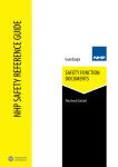
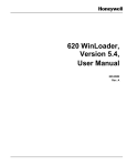
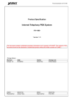
INSTALLATION INSTRUCTIONS 590-00 PROGRAMMABLE CONTROLLER 590 PROGRAMMABLE CONTROLLER T U TP U O E ET EL D M R FI N O C AM R G O R PR RO ER Infrared Sensor FRONT PANEL The front panel of the 590 is made of acrylic plastic. It should be cleaned with a soft cloth as it scratches easily. Behind the panel are five red LEDs and an infrared sensor. RED LEDs PROGRAM - Lights when the PGM (program) button on the rear panel is pressed. CONFIRM - Lights after a command has been memorized during programming. DELETE - Blinks on and off when the DELETE button on the rear panel is pressed. OUTPUT - Lights to indicate when infrared commands are being sent in response to a contact closure. Contact closure is the most common form of input to the 590. If other types of inputs are used, they will perform the same function as contact closures. INFRARED SENSOR Receives IR commands for programming the 590. It is located about one-half inch above the OUTPUT lamp. RES DEL SEQ PGM ON 1 2 3 4 + 1 2 3 4 5 6 7 8 12VDC 9 10 11 12 13 14 15 16 O G – + 1234 BANK 12VDC – REAR PANEL The following connectors, push-buttons and controls are located on the rear panel: 12VDC jack – the power supply plugs in here (center conductor is positive). BUTTONS (Recessed - press with a pencil point or narrow blade screw driver). RES - Reset - erases all stored commands. DEL - Delete - allows erasure of selected commands. SEQ - Sequence - begins and ends sequence mode programming. PGM - Program - begins and ends learning mode. BANK - Bank DIP Switch – Selects one of four memory banks on microprocessor. 1 Controllers ERROR - Lights when an error occurs in the learning process or when trying to send an unprogrammed command. SCREW TERMINALS Opto-Isolator Inputs - 16 pairs of positive and negative terminals, isolated from ground. O - Infrared Output - Positive terminal for the IR output signal. G - Ground - Negative terminal for the IR output signal. The "O" and "G" terminals drive IR emitters directly or the IR input of Xantech connecting blocks, IR routers, interface modules, etc. 12VDC - 12 volts output, positive & negative terminals. INPUTS A decision as to the type of external input(s) must be made. Figs. 1 & 2 show some examples. The LED inside each opto-isolator within the 590 must pass current in order for the unit to recognize an input. This is accomplished by applying a momentary 5 to 30 volts DC input to these 16 circuits. While many types of switch closures to do this are possible, we will discuss only one for simplicity, the Model 598 key pad. Fig. 1 shows the 598 providing contact closures to activate 8 of the 16 opto-isolator inputs. +12V DC C 1 2 3 4 5 6 7 8 C 1 2 3 4 5 6 7 8 Wire size typically AWG 20-24 Model 590 (rear panel) RES DEL SEQ PGM ON + 1 Model 598 Key Pad (rear view) OUTPUT 2 3 4 5 6 7 8 9 10 11 12 13 14 15 16 O G 1234 BANK 12VDC – Ground or "–" return wires. See Step 3 under "PROGRAMMING" 12VDC – + White Striped Side (output) 786-00 Power Supply The "O" and "G" terminals on the rear panel will drive Emitter, Connecting Block, etc. IR emitters direct or the SIGNAL IN of Xantech connecting blocks, controllers, etc. If a single model Fig. 1 Typical connections when using a 598 Keypad with a 590 Programmable Controller. 282, 283, 284 or 286 Mini-Emitter(s) is to be used, cut off the plug, strip the leads, and connect the wire with the white stripe to "O" and the black wire to "G". For the connection of more emitters, use Xantech Connecting Blocks model 789-44 or 791-44. In this case, connect the "O" and "G" terminals to the "INPUT" and "GROUND", respectively, on the Connecting Blocks. 120 V AC Unswitched The 590 output circuit has the same electrical characteristics as the infrared receivers and key pads in Xantech’s broad line of remote control extension systems and therefore can be wired as part of a larger system. TURN IT ON Plug the power supply into the 12VDC jack on the 590 then plug it into a wall outlet. The five red LEDs (ERROR, PROGRAM, CONFIRM, DELETE and OUTPUT) on the front of the 590 should be off. If any of them are on, unplug the power supply from the wall, wait 10 to 15 seconds and plug it in again. Repeat this process until all of the lamps are off. PROGRAMMING Before programming the 590, press the RES (reset) button on the rear panel. This will clear any data stored during factory testing. Do not push this button again unless you wish to erase ALL of the programming information which you have entered. There is no way to restore this information except by reprogramming. NOTE: FOR THE SAKE OF CLARITY, EXTERNAL CONTACT CLOSURES WILL BE REFERRED TO AS "KEYS" THROUGHOUT THIS MANUAL (whether made with a push-button or a wire connected to the +12V DC terminal and held to the + terminal of the desired input. Refer to step 3 following). Programming Procedure: 1. Press the PGM (program) button on the rear panel. The PROGRAM lamp on the front panel will light. 2. Place the "teaching" hand-held remote control two to four inches in front of the 590. Point it directly at the internal Infrared Sensor (located just above the OUTPUT LED on the 590's front panel). 2 590-00 3. Press and hold down the key for the 590 input into which you wish to store the command. Remember, the "key" may be a contact closure push-button device, such as the Xantech 598 keypad (Fig. 1), or a simple jumper wire, one end connected to the"+" 12VDC terminal and the other end held temporarily onto the "+" terminal of the desired input. NOTE: In either case, you must have previously connected ground wires from each of the "–" terminals of the inputs you are using back to the "–" 12VDC terminal on the 590 as shown in Fig. 1. 4. Press and release the button on the remote control that you wish to store. The 590 PROGRAM lamp will flicker while the information is being stored. 5. When the information has been stored, the CONFIRM lamp will turn on. You can now release the key for the 590. The CONFIRM lamp will turn off. NOTE: If the error LED flashes, you may have a longer code that requires extended memory. See "ERROR LAMP AND EXTENDED MEMORY" section, below. You have now programmed one command function; one input on the 590 has been programmed to send the same infrared command as the key which you have pressed on the hand-held remote control. Steps 2 through 5 must be repeated for each additional command you wish to store in the other 590 inputs. 6. When you have finished storing commands, press the PGM button again to take the 590 out of the program mode. The PROGRAM lamp on the front panel will go off. Testing Stored Commands Press any of the keys (or touch the wire) on any of the 590 inputs you have programmed. The OUTPUT LED will flash, the CONFIRM LED will light and the command should be executed on the audio/video equipment. ERROR LAMP AND EXTENDED MEMORY Some remote control codes require more memory than is normally allocated by the 590’s microprocessor. When you try to program one of these codes, the PROGRAM lamp will blink at a slower rate and will be followed by a very short flash of the ERROR lamp. The flash of the ERROR lamp is so short that you may not notice it the first time it occurs. If this happens, no command will be stored in memory. To store these commands, you must go through steps 2 through 5 twice. The 590 will then allocate four times as much memory on the second pass as it did on the first. If one command from a hand-held remote controller requires extended memory, the other commands from that controller usually will also require extended memory. DELETE BUTTON The DEL (delete) button on the rear panel can be used to erase any individual command. The PROGRAM lamp on the front panel must not be lit. If it is, press the PGM button. The PROGRAM lamp will turn off. Press the DEL button. The DELETE lamp will blink continuously. Press the key which has been programmed with the command you wish to erase. The DELETE lamp will turn off. You may now, if you wish, reprogram the key. NOTE: You may overwrite any programmed key with a new command by simply following the PROGRAMMING procedure -- it is not necessary to use the delete button in this case. SHORT COMMANDS Some commands, such as Channel Up and Channel Down, may skip channels or cause other multiple actions if memorized at a long length. If a key on the original hand-held remote controller requires only a 590-00 3 Controllers Sixteen (16) different commands may be stored in this manner on each of the four (4) banks. Again, you must provide a "key" or a wired contact closure, as described above, at every 590 input into which you wish to store commands. short tap for its command to be properly executed, then only a short burst of it should be stored in the 590. Step 4 would, therefore, be modified as follows: 4. Press the key on the remote controller that you wish to store. Hold the key for a very short period of time or only as long as you usually press it when controlling the audio/video equipment directly. The PROGRAM lamp will flicker while the information is being stored. SEQUENCE FUNCTION The 590 can also be programmed so that one or more keys can execute up to ten separate commands each that have been previously stored on other individual keys. A single press of a key, programmed with a sequence of commands, will then activate multiple command functions on the IR controlled units in a system. Individual commands must first be stored into the 590 before programming a sequence. In order to explain the function of sequencing, the following example of a key pad configured for a VCR will be used. In this simple example, an AM/FM receiver will be turned ON, the VCR input selected & a VCR turned ON. Begin by first storing the individual commands that you want in the sequence. We recommend storing them on another bank such as Bank 2 and reserving Bank 1 for executing the sequences. NOTE: You can only use one bank for the final execution of commands from the 590 since the bank DIP switches are not available to the user. The additional three banks are provided solely for the purpose of storing commands for use in sequences! A) Store the ON/OFF command of the receiver on Bank 2 in any desired inmput (1-16). (You must keep a record of thrse hidden commands). B) Store the VCR Source Input command of the receiver on another input on Bank 2. C) Store the VCR power ON/OFF command on a third input on Bank 2. We can now set up the following sequence: 1) Turn receiver ON 2) Turn VCR ON 3) Select VCR Input on receiver. We have purposely placed the VCR input command to follow the VCR ON/OFF command. This allows the AM/FM receiver a second or two to stabilize before giving it a second command. The sequence will be stored in a key (input) we will call the ON/OFF key. Sequence Programming Procedure: 1. Press PGM (program) button to enter learn mode (PROGRAM lamp will light). 2. Move Bank 1 DIP switch to ON. Be sure all the others are OFF. 3. Push SEQ (sequence) button. 4. Press the key (or touch the +12V wire) on Bank 1 into which you wish to store the sequence. In this case, we will call it the ON/OFF key. 5. Move Bank 1 DIP switch to OFF and Bank 2 DIP switch to ON. 6. Press the key containing the ON/OFF command for the AM/FM receiver. 7. Press the key containing the ON/OFF command for the VCR. 8. Press the key containing the VCR Input command for the AM/FM receiver. 9. Press the SEQ button to leave the sequence mode. 10. Press the PGM button to leave the program mode (PROGRAM lamp goes off). 11. Move the Bank 1 DIP switch to ON and the Bank 2 DIP switch to OFF. 4 590-00 A sequence is completed. You may now test it by pressing the ON/OFF key (bank 1). It should now send the three commands to turn the AM/FM receiver ON, turn the VCR ON and select the VCR Input on the receiver, in that order. USING THE 590 PROGRAMMABLE CONTROLLER WITH NONMOMENTARY INPUTS The Model 590 was designed to be used with momentary contact switches. In such applications, a button is pressed, the 590 generates an IR command, and the button is released. If the button is not released, the 590 will either continue to repeat the same IR command or send no signal at all after the initial burst. As long as one key is pressed, subsequent actions will be locked out; the other keys (inputs) will not respond. Sometimes it is desirable to have an IR command generated in response to some change or action to trigger automated functions in an audio/video system. • For example, if an AM/FM receiver is turned ON manually, an IR command sequence can be made to turn a TV set ON and set the channel to 4 at the same time. • When the AM/FM receiver is turned OFF manually, an IR command can also turn the TV set OFF. + – 599 IN+ IN– Model 781C or any 5 to 30 V DC Power Supply will work GND PULSED SWITCHING MODULE +12V Controllers 120 V AC From a Switched Source OFF ON GND +12V +12V DC ® SYLMAR, CA • MADE IN U.S.A. Model 590 (rear panel) RES DEL SEQ PGM ON + 1 2 3 4 5 6 7 8 9 10 11 12 13 14 15 16 O G 12VDC – + 1234 BANK 12VDC – Momentary Switches for other system devices Ground or "–" return wires. Fig. 2 Using a 599 Pulsed Switching Module with the 590. 120 V AC Unswitched White Striped Side 786-00 Power Emitter, Connecting Block, etc. Supply • To do this, the presence or absence of a constant ON and OFF DC voltage must be converted to momentary pulses to properly operate the Model 590. • This can be done by using the Model 599 Pulsed Switching Module, connected as shown in Fig. 2. Connect to 590 in same manner as above IN+ SPST Sensing Switch IN– GND 599 PULSED SWITCHING MODULE +12V OFF ON GND +12V ® SYLMAR, CA • MADE IN U.S.A. Fig. 3 Using a SPST Sensing Switch with a 599 for special applications. 590-00 5 • By plugging the Model 781C-00 power supply into the switched AC outlet on the back of a stereo receiver, a constant 12V DC is applied to the 599. The 599 generates a short pulse (+12V, 100 mSec) at its ON terminal when it first sees +5 to +30V DC at its IN+ and IN– terminals (the stereo receiver is turned on). • Similarly, it will generate a short pulse at its OFF terminal (+12V, 100 mSec) when the +5 to +30 volts drops to 0 volts (the stereo receiver is turned off). • This short pulse operation also permits momentary switches to be connected to other inputs on the 590 (such as inputs 1 and 2, as in Fig. 2). This allows additional system commands, other than those activated by the 599, to be executed uninhibited. Fig. 3 shows another example of how a DC control voltage is converted to momentary ON and OFF pulses by the 599 Pulsed Switching Module. • For instance, a special SPST sensing switch, as shown, could be mounted in the springs of an over-stuffed chair. • When someone sits down in the chair, the SPST switch is closed causing the 599 to trigger a sequence of IR commands stored in the 590. The IR commands could cause the room lights to dim, the drapes to close, and music to emanate from the speakers. • When the chair is no longer occupied, the SPST switch opens, triggering another set of sequenced commands. These, in turn, could cause the lights to brighten, the drapes to open & the music to turn off. • Many other applications are possible, limited only by the imagination and needs of the installer and user. --- IMPORTANT --• The 590 inputs that are to be activated by the 599 Pulsed Switching Module must first be programmed with the necessary commands before connecting the 599. • Do this by using the connections and procedures as previously mentioned. • The 590 cannot be programmed through the 599! 590-00 SPECIFICATIONS • INPUTS: 16 Opto-Isolators connected via 16 screw terminal pairs, each in series with a 1k Ohm resistor. Input voltage range, 5 to 30 Volts DC. All isolated - no common ground connections. Drive current for each input is 11 mA at 12V DC. 12V DC is available on the 12VDC "+" and "–" screw terminals for driving inputs through external switch closures. • BANKS: Four. 16 commands per bank. • IR OUT: 2 screw terminals marked "O" (output) and "G" (Gnd.). Same electrical characteristics as Xantech IR Receivers and key pads. • POWER IN: 12VDC, 300 mA. 2.1 mm coaxial jack, center positive. Uses Model 786-00 Power Supply (included). • MEMORY: 64k RAM. Lithium battery backup. • IR CARRIER FREQUENCY: 21.74 kHz to 62.50 kHz learning bandwidth. • Dimensions: 6 1/4" W x 2" H x 4" D 9-23-98 6 590-00