1
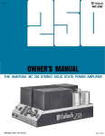
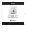
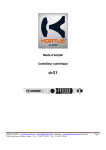
INSTALLATION INSTRUCTIONS 760-00 MATCH MAKER™ SPEAKER VOLUME CONTROL The Model 760-00 is an in-wall mountable stereo speaker volume control with impedance matching capability. From one to sixteen pairs of stereo speakers may be driven from one stereo power amplifier, using an equal number of 760's. It maintains correct impedance matching between the amplifier and the speakers by the use of instant setting S1, S4 and S8 jumpers on the control. This eliminates the need for separate impedance matching components in multi-room installations. OUTPUT L+ L– R– R+ ® 760-00 SYLMAR, CA SPEAKER VOLUME CONTROL INPUT L+ L– R– R+ Fig. 1 The 760-00 SPECIFICATIONS: Type: 2 channel TRI-FI™ wound precision autoformers, with independent grounds. Terminals: Eight plug-in type screw terminals. Power Rating: 25 Watts continuous, 150 Watts peak. Freq.Response: 20-20,000 Hz ± 1dB at 1 watt. 11 steps at 3 to 6 dB per step - 35 dB max. (Max. CCW position is OFF). S1 setting: 0 dB @ Max. CW (pass-through position). S4 setting: 9 dB @ Max. CW. S8 setting: 13 dB @ Max. CW. Impedance: S1 setting: Pass-through position. i.e. 8 Ohms on OUTPUT reflects 8 Ohms to INPUT (Max. CW position). S4 setting: 8 Ohms on OUTPUT reflects 32 Ohms to INPUT . Likewise, 4 Ohms on OUTPUT reflects 16 Ohms to INPUT (Max. CW position). S8 setting: 8 Ohms on OUTPUT reflects 64 Ohms to INPUT. Likewise, 4 Ohms on OUTPUT reflects 32 Ohms to INPUT (Max. CW position). Mounting: Fits most new construction junction boxes - uses single space. Note: Will not fit certain retro-fit boxes, such as the Carlon 14 and 25 cu. inch series. Be sure to check fit before choosing J-boxes! Dimensions: 1-5/8" W x 2-7/8" H x 2-5/16" D 1 Speakers & Volume Controls Attenuation: SETTING THE IMPEDANCE MATCHING JUMPERS Fig. 2 shows the location of the pins and the jumper locations on the pins for the three impedance multiplier positions. To set the jumpers correctly, refer to Fig. 2 and the charts and procedures that follow. Right Channel Jumper Right Channel Jumper Positions S1 S4 S8 S1 S4 S8 SPEAKER VOLUME CONTROL 760-00 ® SYLMAR, CA S8 S4 S1 INPUT L+ L– R– R+ S8 S4 OUTPUT L+ L– R– R+ S1 Left Channel Jumper Positions Left Channel Jumper Fig. 2 Jumper Placement For Impedance Matching The jumpers are located under the one side of the autoformers as shown in Fig.2. Their proper placement depends on the number of 760's and speakers used in the total installation. To set them for the best impedance matching condition, refer to the following charts and procedures: WHEN USING 8 OHM SPEAKERS Min. Amp. Impedance Number of Speaker Pairs Used 1 2 3 4 5 6 7 4 Ohms S1 S1 S4 S4 S4 S4 S4 S4 S8 8 9 8 Ohms S1 S4 S4 S4 S8 S8 S8 S8 10 11 12 13 14 15 16 S8 S8 S8 S8 S8 S8 S8 WHEN USING 4 OHM SPEAKERS 4 Ohms S1 S4 S4 S4 8 Ohms S4 S4 S8 S8 S8 S8 S8 S8 Procedure for all 4 Ohm or all 8 Ohm Speakers: Amplifiers & Preamplifiers Min. Amp. Number of Speaker Pairs Used Impedance 1 2 3 4 5 6 7 8 1. Determine the rated speaker impedance (refer to the manufacturer's specifications - it must be the same for all speakers used in the system). 2. Determine the total number of stereo speaker pairs used in the installation. 3. Determine the minimum safe amplifier operating load impedance (refer to the manufacturer's specifications). 4. Find the correct jumper position from the above charts. 5. Place the jumpers in the same position on each 760 used in the system. Example 1: Three pairs of 4 Ohm wall speakers are to be used with three 760's in a 3-room system, all driven by one amplifier rated for 8 Ohms minimum safe operating load impedance. 1. Refer to the chart "WHEN USING 4OHM SPEAKERS". 2. Locate the number 3 in the top row. 2 760-00 3. On the 3rd row, opposite "8 OHMS" and below "3", note the letters "S8". These signify the required impedance multiplier. 4. The two jumpers therefore, one for each channel, need to be plugged onto the S8 pins on each 760 in each room. Example 2: Seven pairs of 8 Ohm wall speakers are to be used with seven 760's in a 7-room system, all driven by one amplifier rated for 4 Ohms minimum safe operating load impedance. 1. Refer to the chart "WHEN USING 8 OHM SPEAKERS". 2. Locate the number 7 in the top row. 3. On the next row, opposite "4 OHMS" and just below "7", note the letters "S4". These signify the required impedance multiplier. 4. The two jumpers therefore, one for each channel, need to be plugged onto the S4 pins on each 760 that feeds each room. Procedure for Speakers Other Than 4 or 8 Ohms: In this case, some calculation is required. You need to find the total paralleled impedance of the speakers first, then multiply it by 1, 4, or 8 until a value is reached that is higher than the minimum safe value specified for the amplifier. Example: Six pairs of 5 Ohm wall speakers are to be used with six 760's in a 6-room system, all driven by one amplifier rated for 4 Ohms minimum safe operating load impedance. 1. Calculate the total paralleled impedance by dividing 5 Ohms by 6. 5 ÷ 6 = 0.83 Ohms. 2. Multiply 0.83 by 4 (for the S4 setting) = 3.32 Ohms. Since this value is less than 4 Ohms, the S4 setting cannot be used. 3. Multiply 0.83 by 8 (for the S8 setting) = 6.64 Ohms. Since this yields more than 4 Ohms, the S8 setting is the correct one to use. NOTE: Always use the lowest "S" number consistent with the minimum safe load impedance required. Higher "S" values would be "safe" but would result in an unnecessary reduction in power level delivered to each speaker. Procedure for Speakers of Differing Impedance Used in the Same System Example 1: 2 pairs of 4 Ohm and 7 pairs of 8 Ohm wall speakers are to be used with nine 760's in a 9-room system, all driven by one amplifier rated for 4 Ohms min. safe operating load impedance. 1. Calculate the total paralleled impedance of 4 Ohm group first, by dividing 4 Ohms by 2. 4 ÷ 2 = 2 Ohms. 2. Multiply 2 by 4 (for the S4 setting) = 8 Ohms. 3. Calculate the total paralleled impedance of 8 Ohm group next, divide 8 Ohms by 7. 8 ÷ 7 = 1.14 Ohms. 4. Multiply 1.14 by 8 (for the S8 setting) = 9.12 Ohms. 760-00 3 Speakers & Volume Controls You may run into installations where you need to combine speakers of different impedance in the same system (8, 6, 4 Ohms, etc.). This is a more complicated situation that requires additional calculation. The procedure is similar to the preceding example, except you need to find the paralleled impedance for each group of speakers with the same impedance first and pick an "S" setting for each. Then check the overall paralleled "S" settings to see that the impedance is higher than the minimum safe value specified for the amplifier. 5. Next, calculate the overall paralleled impedance with the following formulae: ZO = 1 ÷ [(1÷Z1) + (1÷Z2) + (1÷ZN...etc.)] ZO = overall paralleled impedance Z1 = 1st paralleled group after S setting Z2 = 2nd paralleled group after S setting ZN = additional paralleled groups, when used. Since only two paralleled groups are used in this example, the calculation is as follows: ZO = 1 ÷ [(1÷8) + (1÷9.12)] = 4.26 Ohms. Since this yields more than 4 Ohms, the S4 setting for the 4 Ohm group and the S8 setting for the 8 Ohm group are the correct ones to use. Example 2: 2 pairs of 4 Ohm, 3 pairs of 6 Ohm and 3 pairs of 8 Ohm wall speakers are to be used with eight 760's in an 8-room system, all driven by one amplifier rated for 4 Ohms minimum safe operating load impedance. 1. Calculate the total paralleled impedance of 4 Ohm group first, by dividing 4 Ohms by 2. 4 ÷ 2 = 2 Ohms. 2. Multiply 2 by 4 (for the S4 setting) = 8 Ohms. 3. Calculate the total paralleled impedance of 6 Ohm group next, by dividing 6 Ohms by 3. 6 ÷ 3 = 2 Ohms. 4. Multiply 2 by 8 (for the S8 setting) = 16 Ohms. 5. Calculate the total paralleled impedance of 8 Ohm group next, by dividing 8 Ohms by 3. 8 ÷ 3 = 2.67 Ohms. 6. Multiply 2.67 by 8 (S8 setting) = 21.36 Ohms. 7. Next, calculate the overall paralleled impedance ZO. Since three paralleled groups are used, the calculation is as follows: ZO = 1 ÷ [(1÷8) + (1÷16) + (1÷21.36)] = 4.27 Ohms. Since this yields more than 4 Ohms, the S4 setting for the 4 Ohm group, the S8 setting for the 6 Ohm group and the S8 setting for the 8 Ohm group are the correct ones to use. Impedance Setting Tips 1. You may use the above method to calculate the correct impedance matching condition for practically any combination of speakers and 760s. 2. Use the lowest "S" setting possible consistent with the requirement to keep above the minimum safe operating load impedance for the amplifier. You may have to try 2 or 3 values of "S" for each impedance group and recalculate the overall paralleled impedance ZO each time, before you arrive at the final correct value. 3. When you test the system, you may find volume differences between the impedance groups when all 760s are set to max. volume. This is normal and is usually not a problem, since the user will be listening at lower levels most of the time. If you feel it necessary to even out the volume levels, move the "S" jumpers to the next higher number on the 760s that feed the loudest group. NOTE: While speakers of differing impedance can be accommodated using these procedures, it is highly recommended you not do so on a regular basis. The easiest and best performing installation is achieved by using speakers of the same impedance throughout the entire system, referring to the charts for the jumper "S" settings. 4 760-00 INSTALLATION As shown in Fig. 3, 4-conductor speaker wire (two wires for each channel) is connected from each of the 760's to the power amplifier (home run from each room). Also, each channel (left and right) requires a pair of wires from the 760 to the speakers. The plug-in connectors and the printed circuit board of the 760-00 are marked with the terminal identifications. CAUTION: Be sure the amplifier or receiver speaker terminals are connected to the INPUT terminals on the 760-00 and the speakers are connected to the OUTPUT terminals on the 760-00 as shown in Fig.3! The negative right input wire (INPUT R–) and the negative right output wire (OUTPUT R–) are connected together in the 760-00. Likewise, INPUT L– and OUTPUT L– are connected together. There are no common ground connections between the left and right channels in the 760-00, allowing bridged type amplifiers to be used, if desired. MOUNTING: The 760-00 is intended to be housed in an electrical junction box and trimmed with a decorator-style plate (not included). The decorator-style plastic insert plate (supplied) is available in either white or ivory. 4 plastic tabs allow it to be snapped into place onto the metal mounting plate. It can be easily removed for refinishing to other colors, if desired, by squeezing the tips of the tabs together while pulling outward on the insert plate. Be sure to remove the push-on knob first. Refer to Fig. 4. CAUTION: Stereo receivers usually have two sets of speaker terminals, "A" and "B". Be sure all speakers connected to both "A" and "B" are taken into consideration when paralleling speakers, so that the amplifiers are not loaded by an impedance that is lower than that specified by the manufacturer. SPEAKER TERMINALS L+ L- AMPLIFIER OR RECEIVER R- R+ CB18 "THE STRIP-IR" CONNECTING BLOCK 8 L+ L- R- R+ 7 L+ L- R- R+ 6 L+ L- R- R+ 5 L+ L- R- R+ 4 L+ L- R- R+ 3 L+ L- R- R+ 2 L+ L- R- R+ L+ L- R- R+ L+ L- R- R+ 1 9 Use the CB18 to simplify multiple speaker wire connections. SYLMAR, CA SPEAKER VOLUME CONTROL LEFT SPEAKER RIGHT SPEAKER ® 760-00 + – – + – + ROOM 1 SYLMAR, CA SPEAKER VOLUME CONTROL OUTPUT L+ L– R– R+ LEFT SPEAKER ® 760-00 OUTPUT L+ L– R– R+ + – RIGHT SPEAKER INPUT L+ L– R– R+ ROOM 2 – + SYLMAR, CA ® INPUT L+ L– R– R+ OUTPUT L+ L– R– R+ 760-00 760-00 MATCH MAKER Speaker Volume Controls (side view) RIGHT SPEAKER + – LEFT SPEAKER ROOM 3 Fig. 3. A Typical 3-Room System 760-00 5 Speakers & Volume Controls SPEAKER VOLUME CONTROL INPUT L+ L– R– R+ The metal mounting plate of the 760-00 is attached to wall J-boxes using the two 6-32 pan-head screws supplied. See Fig. 4. Slots are provided in the metal bracket so that adjustments can be made in the alignment of the 760. CAUTION: THE ELECTRICAL JUNCTION BOX, IN WHICH THE 760-00 IS MOUNTED, MUST BE DEDICATED TO LOW VOLTAGE A/V SYSTEM APPLICATIONS. MAKE SURE THAT NO AC MAINS WIRING PASSES THROUGH OR TERMINATES IN THIS BOX! Combinations of 760-00’s and other A/V devices however, may be mounted together in multi-gang boxes. OUTPUT L+ L– R– R+ Tabs (4) ® 760-00 SYLMAR, CA SPEAKER VOLUME CONTROL Plastic Insert Plate (included) Metal Mounting Plate (included) INPUT L+ L– R– R+ J-Box (new construction) Wallboard Knob (included) Decorator Cover Plate & 2 Screws (not included) 6-32 Screws (2) (included) Fig. 4. 760 Mounting Details 8-10-98 6 760-00