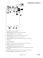
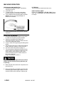
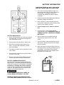
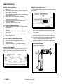
1
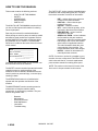
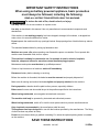
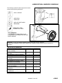
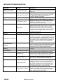
LIGHTNING
BATTERY POWERED HIGH SPEED BURNISHER
Operating Instructions (ENG)
Bedienungsanleitung (GER)
MODEL:
L20
10027100
L20T
10027110
Read these instructions before operating the machine.
Bitte lesen Sie diese Anleitungen, bevor Sie die Maschine in Gebrauch nehmen
86038450 - AV 10/20/08
PRV NO. 98753
MACHINE DATA LOG
MODEL _______________________________________
DATE OF PURCHASE __________________________
SERIAL NUMBER ______________________________
SALES REPRESENTATIVE # _____________________
Copyright 1995 Windsor Industries, Printed in USA
YOUR DEALER
Name: __________________________________________________________________________________________________
Address: _______________________________________________________________________________________________
Phone Number: _________________________________________________________________________________________
2ENG
86038450 04/12/07
TABLE OF CONTENTS
Machine Data Log. ...............................................2
Table of Contents.................................................3
HOW TO USE THIS MANUAL
How to use this Manual........................................1-1
SAFETY
Important Safety Instructions ...............................2-1
Hazard Intensity Level..........................................2-2
GROUP PARTS LIST
Chassis/Drive Assembly Group. ..........................5-1
Deck Lift Mechanism. ...........................................5-3
Electrical Controls Group .....................................5-5
Handle Assembly .................................................5-7
Hood Group..........................................................5-9
Lift Linkage Group. ............................................. 5-11
Wiring Schematic (Non-traction). ....................... 5-13
Wiring Schematic (Traction). .............................. 5-15
Suggested Spare Parts ...................................... 5-18
Notes .................................................................. 5-19
OPERATIONS
Components/Controls ..........................................3-1
Machine Operation...............................................3-2
Pre-Run Machine Inspection ............................3-2
Operating the Machine......................................3-2
Filter Bag. ..........................................................3-2
Dust Control Skirt ..............................................3-2
MAINTENANCE
Battery Information...............................................4-1
Battery Connection...........................................4-1
Battery Maintenance. .......................................4-1
Battery Charging Procedure. ...........................4-1
Maintenance.........................................................4-2
Weekly Maintenance.........................................4-2
4 to 6 Month Maintenance ................................4-2
Ending Work Periods. .......................................4-2
Shunt Adjustments............................................4-2
Shaft Adjustment...............................................4-2
Lubrication............................................................4-3
Service Schedule .................................................4-3
Machine Troubleshooting.....................................4-4
86038450 04/12/07
3ENG
HOW TO USE THIS MANUAL
The PARTS LIST section contains assembled parts
illustrations and corresponding parts list. The parts
lists include a number of columns of information:
This manual contains the following sections:
-
HOW TO USE THIS MANUAL
SAFETY
OPERATIONS
MAINTENANCE
PARTS LIST
-
The HOW TO USE THIS MANUAL section will tell
you how to find important information for ordering
correct repair parts.
-
Parts may be ordered from authorized dealers.
When placing an order for parts, the machine model
and machine serial number are important. Refer to
the MACHINE DATA box which is filled out during
the installation of your machine. The MACHINE
DATA box is located on the inside of the front cover
of this manual.
-
MODEL _____________________________________
-
DATE OF PURCHASE ________________________
SERIAL NUMBER ____________________________
SALES REPRESENTATIVE # ___________________
Copyright 1995 Windsor Industries, Printed in USA
The model and serial number of your machine is on
the bottom back-end of the machine.
The SAFETY section contains important information
regarding hazard or unsafe practices of the
machine. Levels of hazards is identified that could
result in product or personal injury, or severe injury
resulting in death.
NOTE: If a service or option kit is installed on your
machine, be sure to keep the KIT INSTRUCTIONS
which came with the kit. It contains replacement
parts numbers needed for ordering future parts.
NOTE: The number on the lower left corner of the
front cover is the part number for this manual.
The OPERATIONS section is to familiarize the
operator with the operation and function of the
machine.
The MAINTENANCE section contains preventive
maintenance to keep the machine and its
components in good working condition. They are
listed in this general order:
-
Batteries
Maintenance
Shunt Adjustments
Shaft Adjustment
Lubrication
Troubleshooting
1-1ENG
REF – column refers to the reference
number on the parts illustration.
PART NO. – column lists the part
number for the part.
PRV NO. - reference number.
QTY – column lists the quantity of the
part used in that area of the machine.
DESCRIPTION – column is a brief
description of the part.
SERIAL NO. FROM – column indicates
the first machine the part number is
applicable to. When the machine design
has changed, this column will indicate
serial number of applicable machine.
The main illustration shows the most
current design of the machine. The
boxed illustrations show older designs.
NOTES – column for information not
noted by the other columns.
86038450 04/12/07
IMPORTANT SAFETY INSTRUCTIONS
When using an battery powered appliance, basic precaution
must always be followed, including the following:
READ ALL INSTRUCTIONS BEFORE USING THIS MACHINE.
To reduce the risk of fire, electric shock, or injury:
Use only indoors. Do not use outdoors or expose to rain.
Use only as described in this manual. Use only manufacturer’s recommended components and
attachments.
If the machine is not working properly, has been dropped, damaged, left outdoors, or dropped into
water, return it to an authorized service center.
Do not operate the machine with any openings blocked. Keep openings free of debris that may reduce
airflow.
This machine is not suitable for picking up hazardous dust.
Machine can cause a fire when operating near flammable vapors or materials. Do not operate this
machine near flammable fluids, dust or vapors.
This machine is suitable for commercial use, for example in hotels, schools, hospitals,
factories, shops and offices for more than normal housekeeping purposes.
Maintenance and repairs must be done by qualified personnel.
If foam or liquid comes out of machine, switch off immediately.
Disconnect battery before cleaning or servicing.
Before the machine is discarded, the batteries must be removed and properly disposed of.
Make sure all warning and caution labels are legible and properly attached to the machine.
During operation, attention shall be paid to other persons, especially children.
Before use all covers and doors shall be put in the positions specified in the instructions.
When leaving unattended, secure against unintentional movement.
The machine shall only be operated by instructed and authorized persons.
When leaving unattended, switch off or lock the main power switch to prevent unauthorized use.
Only chemicals recommended by the manufacturer shall be used.
This appliance has been designed for use with the brushes specified by the manufacturer. The fitting
of other brushes may affect its safety.
Do not use on surfaces having a gradient exceeding 2% unless the optional parking brake is installed
on the machine.
SAVE THESE INSTRUCTIONS
86038450 04/12/07
2-1ENG
HAZARD INTENSITY LEVEL
The following symbols are used throughout this guide as indicated in their descriptions:
HAZARD INTENSITY LEVEL
There are three levels of hazard intensity identified by signal words -WARNING and CAUTION and FOR
SAFETY. The level of hazard intensity is determined by the following definitions:
! WARNING
WARNING - Hazards or unsafe practices which COULD result in severe personal injury or death.
! CAUTION
CAUTION - Hazards or unsafe practices which could result in minor personal injury or product or property
damage.
FOR SAFETY: To Identify actions which must be followed for safe operation of equipment.
Report machine damage or faulty operation immediately. Do not use the machine if it is not in proper operating
condition. Following is information that signals some potentially dangerous conditions to the operator or the
equipment. Read this information carefully. Know when these conditions can exist. Locate all safety devices on
the machine. Please take the necessary steps to train the machine operating personnel.
FOR SAFETY:
DO NOT OPERATE MACHINE:
Unless Trained and Authorized.
Unless Operation Guide is Read and understood.
In Flammable or Explosive areas.
In areas with possible falling objects.
WHEN SERVICING MACHINE:
Avoid moving parts. Do not wear loose clothing; jackets, shirts, or sleeves when working on the
machine. Use Windsor approved replacement parts.
! WARNING
Batteries emit hydrogen gas. Explosion or fire can result. Keep sparks and open flame away. Keep
solution tank in raised position when charging. Keep sparks and flames away from the batteries. Do not
smoke around batteries.
! WARNING
Disconnect batteries before working on machine. Only qualified personnel should work inside machine.
Always wear eye protection and protective clothing when working on or near batteries. Avoid skin contact
with the acid contained in the batteries.
! WARNING
Never allow metal to lie across battery tops.
2-2ENG
86038450 04/12/07
COMPONENTS/CONTROLS
13
12
1.
Hour Meter. Records machine use time.
2.
Battery Condition Light. Indicates the charge condition of batteries.
3.
Main Power Switch. Turns On and Off the machine.
4.
Pad Pressure Meter. “Green Area” indicates correct pad pressure range.
5.
Burnishing Head Switch. Raises and lowers burnishing head.
6.
3 Amp Circuit Breaker. Thermal circuit breaker protects lift mechanism. Press to reset.
7.
Main Handle.
8.
Handle Adjustment Lever.
9.
Breaker. 60 amp magnetic circuit breaker, protects pad driver motor. Press to reset.
10. Pad Motor Switch Bar. Raising bar turns on pad driver motor.
11. Pad Adjustment Knob. Rotating knob adjusts pad pressure.
12. Reverse Button (Traction model only). Propel bar must be squeezed and button pushed for
reverse travel.
13. Speed Control (Traction model only). Knob rotated left to right for slow to fast speed.
14. 15 Amp Circuit Breaker (Traction model only). Protects transaxle.
86038450 04/12/07
3-1 ENG
MACHINE OPERATION
PRE-RUN MACHINE INSPECTION
1. Disconnect the battery charger. (See battery
charging procedure).
2. Close the cover.
3. To raise the deck: Turn on the main power
switch and press the burnishing head switch.
4. Turn or install a new burnishing pad as needed.
NOTE: Pad lock has left hand threads. To
loosen turn clockwise.
FILTER BAG
The filter bag is accessed under the cover.
DUST CONTROL SKIRT
Replace skirt (86007290 – PRV NO. 730017) when
worn, torn, or damaged in any way that allows dust
to escape.
5. Check wheels and other pivot points for proper
lubrication.
OPERATING THE MACHINE
1. If using a machine that is already set up, check
to make sure the pad is properly installed.
2. Adjust the operating control handle to a
comfortable position using the handle lock lever.
3. Turn on the main power switch.
4. Lower or raise deck by pressing burnishing head
switch.
5. The pad motor will only run when the burnishing
head is lowered to within 3 inches of the floor.
6. The drive controls are shown on page 3-1.
7. The pad pressure is adjusted using the knob at
center of panel. The operator monitors the amp
draw using the meter located on the control
panel and ensures that the needle remains in
the “green” operating
range. (See page 3-1, #4 & 11).
To prevent possible damage to the floor surface,
always keep the machine moving while the pad
is spinning.
8. When the pad motor switch bar is squeezed, the
pad motor runs.
9. Return the machine to the battery charger when
the battery light indicator light is amber. Do not
operate machine when indicator is flashing red.
3-2ENG
86038450 04/12/07
BATTERY INFORMATION
CHARGE BATTERIES IN A WELL-VENTILATED
AREA WITH DECK DOWN AND COVER OPEN.
1. Use a 36 volt, 20 amp maximum output, D.C.
charger that turns itself off, when batteries are
fully charged. The charger must have a
connector that matches the machine battery
connection.
2. Read the instructions and warnings provided by
the battery charger manufacturer.
3. Set the charger in a well-ventilated area on a
level surface. Make sure cords will easily reach
outlets on both machine and wall.
4. Connect charger to D.C. outlet on machine
first.
5. Connect the A.C. power cord to properly
grounded wall socket. NEVER MAKE THE A.C.
CONNECTION FIRST, HAZARDOUS SPARKS
MAY RESULT.
BATTERY MAINTENANCE
1. When cleaning batteries use a solution of baking
soda and water. (Do not allow cleaning fluid to
enter inside battery cells.)
2. Keep a proper electrolyte level in battery cells.
3. Wipe down the battery tops at least once a
week. If a cell should accidentally overflow,
clean immediately.
4. Test battery condition with a hydrometer at least
once a week.
6. After the batteries are completely charged
disconnect the charger from the A.C. wall
socket.
7. Once the charger is disconnected from the A.C.
wall socket, it is safe to disconnect the charger
from the machine.
8. When the batteries are fully charged, check the
electrolyte level by removing, the caps on top of
the batteries. If necessary fill the cells with
distilled water as shown in the diagram below.
Be careful not to overfill cells.
5. Ensure that all connections are tight and that all
corrosion is removed.
6. Every 4 to 6 months remove batteries from the
machine and clean the battery compartment.
BATTERY CHARGING PROCEDURE
Charge the batteries once the amber charge level
light comes on. The amber light indicates that there
is about 20% charge left in the batteries. Do not let
the batteries completely drain before charging.
Avoid charging the batteries before the amber light
comes on. The machine will run for hours on fully
charged, well maintained batteries.
DO NOT SMOKE, HAVE OPEN FLAMES, OR
SPARKS NEAR BATTERIES AT ANY TIME.
WEAR EYE PROTECTION AND PROTECTIVE
CLOTHING WHEN WORKING WITH BATTERIES.
86038450 04/12/07
4-1ENG
MAINTENANCE
WEEKLY MAINTENANCE
1. Use a hydrometer to check the condition of each
battery cell.
2. Check battery cable clamps. Ensure clamps are
tight on battery terminals.
3. Clean tops of batteries with a wet cloth and a
solution of water and baking soda. Wipe battery
tops dry after cleaning.
4. Check pad lock for looseness or damage.
5. Check filter and filter seals. Airflow should be
unobstructed through filter.
6. Ensure that the pivot points and casters are
properly lubricated.
7. Tighten any loose screws or nuts.
4 TO 6 MONTH MAINTENANCE
1. Remove batteries-clean battery tray and battery
compartment.
2. Clean battery cable clamps and battery
terminals.
3. Check the carbon motor brushes in the pad
driver motor.
4. Use a vacuum to remove lint or dust build-up
from motor windings.
5. Grease axles.
AT THE END OF EACH WORK PERIOD:
1. Wipe down the exterior of the machine.
2. Lower the deck.
3. Open the cover.
4. Charge the batteries. (See battery charging
procedure on page 4-1.)
SHUNT ADJUSTMENT (Cont.)
Check the amp range when nuisance tripping of the
circuit breaker indicates that the shunt may be out of
adjustment.
1. Connect a DC ampere meter to the positive
battery lead. Running the machine with a pad,
lower the pad to the floor until it is operating at
55-60 amps.
2. Moving the wire in the slot, adjust the pad
pressure meter until the needle sets at the line
between the green and red areas.
3. Check the other points indicated in the diagram
above. The high end should trip the circuit
breaker. Replace the pad pressure meter if the
approximate amp ranges shown cannot be set.
SHAFT ADJUSTMENT
If shaft is replaced make sure it is adjusted
correctly upon installation.
SHUNT ADJUSTMENT
This pad pressure meter adjustment is factory set.
Over the course of time it may become necessary to
adjust this setting using the slotted connection on
the shunt.
5/8"
4-2ENG
86038450 04/12/07
LUBRICATION & SERVICE SCHEDULE
The following symbols found throughout the manual
indicate items requiring lubrication:
APPLY GREASE
USE SPRAY
LUBRICANT
ANTISEIZE
USE ANTI-SEIZE WHEN
REPAIRING
PERMANENT (RED)
THREAD LOCK TIGHT
AXLE GREASING:
1-2 STROKES OF MOBILTEMP©78 OR
COMPATIBLE CLAY-BASED OR CALCIUMBASED GREASE.
NOTES:
CAUTION: Do not use pressure washers to clean sealed gear boxes or bearings.
If it becomes necessary to clean under machine with a pressure washer; Ensure all items noted are relubricated
SERVICE SCHEDULE
MAINTENANCE
Check batteries after charging; add
water if necessary
Check pad wear to prevent buildup of
chemicals
Check pad driver system for damage
Check bag/filter
Check handles, switches, and knobs
for damage
Store with pad off the floor
Check batteries for corrosion, cracks
and evidence of overheating
Check all bearings for noise
Check skirt/bumpers for damage and
replace as necessary
Grease wheels and casters (if
appropriate)
Check potentiometer (speed control)
for adjustment
Check overall performance of machine
DAILY
MONTHLY
*
*
*
*
*
*
*
*
*
*
*
*
86038450 04/12/07
4-3ENG
MACHINE TROUBLESHOOTING
PROBLEM
CAUSE
SOLUTION
No power to machine
Poor Cable Connection
Faulty Main Power Switch
Pad motor won’t run
Circuit breaker has tripped
Actuator Safety Switch
Faulty Relay
Deck lift mechanism not
working
Circuit breaker has tripped
Deck switch not working
Deck actuator not
working
Handle switch not
working
Drive Controls
Circuit breaker has tripped.
Bad switch (es).
Loose connection.
Faulty potentiometer.
Faulty drive control board.
4-4ENG
Clean battery cable clamps of any corrosion and
tighten. Test voltage at points G to B should be from 34
to 38 VDC.
With the main power switch turned on, test voltage at
points D to B should be from 34 to 38 VDC. If there is
no voltage remove leads and check switch for
continuity. Replace if necessary
Reset circuit breaker (H).
With main power on, pad lowered to floor, switch bar
pulled up, test voltage at L (wire #2) to B (rear panel)
should be 34 to 38 VDC. If not, check and adjust or
replace safety switch as necessary.
With main power on, pad lowered to floor and drive
handle squeezed: Test voltage at points F to B and A to
B should be from 34 to 38 VDC. When the relay is
working it should make a clicking noise as the drive
handle is squeezed. Replace relay if the test voltage F
to B is OK. If test voltage F to B is not OK, check all
wiring to pad motor relay.
Reset circuit breaker (J).
With main switch on, test voltage at C (5) to C (2)
should be 34 to 38 VDC. If not check circuit breaker (J)
and main power switch. If the test voltage at C (5) to C
(2) is 34 to 38 VDC, the voltage at deck switch C (3) to
C (6) should be 34 to 38 VDC when the deck switch is
pressed to raise/lower the pad. If not, replace deck
switch.
If the deck switch tested OK, but the deck lift actuator
still is not working, disconnect the white and black wires
to actuator (K) and apply 36 VDC directly to actuator. If
the actuator does not respond, replace actuator.
Check power from E (wire #1) to B. Check switch
continuity.
Check if power at wire #26. If yes, but breaker has no
power at wire 28 either reset breaker (Q) or replace.
Check continuity at handle switch for non-traction
model. Check continuity at propel switch or pad motor
switch for traction model. Replace as necessary.
Check all connections of propel circuit especially at M,
N, P, R, S & T. Check transaxle connection at U.
With the drive motor disconnected at V, test the output
voltage to the drive motor. The output voltage at V
should vary from 0 to 36V at R & S as the control lever
is squeezed. Resistance of the potentiometer can be
tested at the leads 4 & 1 found at the potentiometer T.
The resistance should vary from 0-50K ohms.
Voltage at T1 (P) to T2 (N) should be from 34 to
38VDC. If the voltage at T1 is good but the propel
motor won't respond, and all the tests above have been
done, replace the drive control board.
86038450 04/12/07
TROUBLESHOOTING.
PROBLEM
Drive controls cont.
CAUSE
SOLUTION
Faulty motor.
Loose Connection.
Machine will not propel
Bad Relay.
Faulty Resistor.
Squeeze the control lever and test the voltage at U (wire
#27 & 28). When the output voltage varies with the
control lever but the motor does not respond and all the
tests above have been done, replace the motor.
With main power on, test voltage at terminal 30 (X) on
Relay should be 34 to 38 VDC. With switch on, check
voltage to wire side of resistor (Y). Should be 34 to 38
VDC.
With main power on, test voltage at terminal 87 (Z)
should be 34 to 38 VDC.
With main power on, test voltage at terminal 85 (AA)
should be 22 to 26 VDC.
86038450 04/12/07
4-5ENG