1
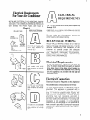
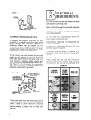
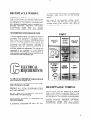
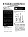
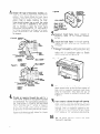
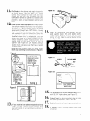
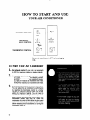
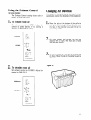
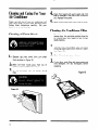
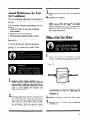
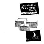
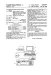
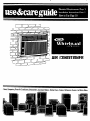
AIR CONDITIONER
- 3
! Ovens, Compactors, Room Air Conditioners, Dehumidifiers, Automatic Washers, Clothes Dryers, Freezers, Refrigerator-Freezers, Ice Makers,Dishw;
BEFORE YOU USE YOUR
AIR CONDITIONER
It is your responsibility to make
sure that your air conditioner:
Has been properly
l
Is the right
to cool.
l
installed.
size for
the area you
Copy your Model and
Serial Numbers here.. .
l
Is properly
connected
to electricity.
l
Is properly
electrically
grounded.
When you need service or call with a question, have
this information ready:
l
1.
for the job it was
Is not used by children
able to operate it properly.
l
Complete Model and Serial Numbers. To
find Model and Serial Numbers remove the
front panel (see page 12). The numbers are
located on a label attached to the evaporator
coil cover near the top of the unit.
SERIAL
Is properly
used only
intended to do.
Is properly
l
want
or anyone
not
maintained.
Also, remove energy label and buy guide.
Use damp cloth to take off any glue
residue. Do not use a sharp instrument
or any harsh or abrasive cleaners.
l
LABEL
Energy Saving Tips
Improve
windows,
l
Purchase date from sales slip.
Copy this information in the spaces below.
Keep this book, your warranty and sales slip
together in a handy place.
l
l
Model Number
l
Serial Number
Purchase Date
.-.
(seal
flue).
Close blinds or drapes on sunny
house; add window awnings.
l
2.
home
insulation
and close fireplace
.
l
l
Keep air filter clean. Don’t
with drapes or furniture.
doors,
side of
block air flow
Ventilate
attic
(high temperature
add to normal cooling load).
levels
Try not to use heat producing appliances
during the hottest part of the day. Turn
other
televisions,
and
lights,
radios,
appliances off when not needed.
Keep heat registers and cool air returns
closed or blocked off so cooled air won’t
escape.
Use a vent fan in areas where cooking,
laundry,
or bathing is done to pull out
extra heat and moisture near its source.
Contents
we
page
Before You Use Your Air Conditioner
Energy Tips ........................
Electrical Requirements
...............
Installation
Instructions
...............
How to Start and
Use Your Air Conditioner
2
............
....
2
2
3
7
10
Cleaning and Caring for Your
Air Conditioner
....................
Cooling Load Guide .................
Self-Service Checklist ................
Service Information
.................
0 1987 Whirlpool
Corporation
12
14
15
15
Electrical Requirements
For Your Air Conditioner
BELOW ARE ELECTRICAL PLUG VARIATIONS, CHOOSE
THE ONE WHICH MATCHES THE AMPERE RATING OF
YOUR UNIT. THE NUMBER OF AMPERES IS PRINTED ON
THE SERIAL LABEL, ATTACHED TO THE FRONT OF THE
UNIT, BEHIND THE FRONT PANEL (SEE PAGE 2).
Chart-A
PLUG TYPE
3-PRONG
GROUNDING
PLUG
S’PRONG
GROUNDING
TYPE WALL
RECEPTACLE
POWER
SEE ELECTRICAL
REQUIREMENTS
n
A
For 115 volt
serial
plate
through
12.0
models with
amperes
up
SUPPLV
n
A
ELECTRICAL
REQUIREMENTS
For 115 volt models with serial plate amperes up
through 12.0
OBSERVE ALL LOCAL
AND ORDINANCES
GOVERNING
Do not, under any circumstances,
power supply cord ground prong.
CODES
remove the
RECEPTACLE WIRING
RECEPTACLE
WIRING
should be at least as
large as 14 gauge. Use copper wire only. It is the
personal responsibility
and obligation
of the
customer
to provide
proper
and adequate
receptacle wiring installed by a qualified electrician. OBSERVE
NATIONAL
ELECTRICAL
CODE
AND
ALL
LOCAL
GOVERNING
CODES AND ORDINANCES.
Electrical Requirements
For 230 volt and 2301208
volt
models
with
serial
plate amperes up through
12.0
A 115 volt (103.5 min., 126.5 max.) 60 hertz AC
only, 15 ampere fused electrical supply is required
(time delay fuse or time delay circuit breaker required). It is required that a separate circuit, serving
only this appliance, be provided. Do not use an
extension cord.
Electrical Connection
Electrical
For 230 volt and 2301208
volt
models
with
serial
plate amperes up through
16.0
Dl
For 230 volt and 2301208
volt
models
with
serial
plate amperes up through
24.0
Ground
RECOMMENDED
is Required
GROUNDING
on this Appliance
METHOD
For your personal safety, this appliance must be
grounded.
This appliance
is equipped
with a
power supply cord having a 3-prong grounding
plug. To minimize
possible shock hazard, the
cord must be plugged into a mating 3-prong
grounding
type wall receptacle, grounded
in
accordance with the National
Electrical
Code
and local codes and ordinances. If a mating wall
receptacle is not available,
it is the peisonal
responsibility
and obligation
of the customer to
have a properly grounded 3-prong wall receptacle
installed by a qualified electrician. See Figure 1
on page 4.
ELECTRICAL
REQUIREMENTS
Figure 1
3-PRONG
GROUNDING
PLUG
I
For 230 volt and 230/208 volt models with serial
plate amperes up through 12.0
TYPE WALL RECEPTACLE
POWER SUPPLY CORD
Refer to Chart B for specific wiring and receptacle
information
to be used.
OBSERVE ALL LOCAL
AND ORDINANCES.
ALTERNATE
GROUNDING
METHOD
If changing and properly
grounding
the wall
receptacle is impossible and where local codes
permit
(consult
your electrical
inspector),
a
temporary
adapter may be plugged into the
existing 2-prong wall receptacle to mate with the
3-prong power supply cord. See Figure 2. THIS,
HOWEVER, IS NOT RECOMMENDED.
If this is done, you must connect the grounded
eyelet on the adapter to the wall receptacle
cover plate screw and from this same screw, you
must connect a separate copper ground wire
(#14 minimum) to a grounded cold water pipe.*
See Figure 2. Do not ground to a gas supply
pipe. Do not connect to electrical supply until
appliance is permanently
grounded.
GROUND ASSEMBLY
(ArrAw
To GROUNDED
/
METAL COLD
WATER PIPE)
ELECTRICALLY
COLD WATER
Do not, under any circumstances,
power supply cord ground plug.
ELECTRICAL
GROUND
THIS APPLIANCE.
A three-wire,
single-phase
electrical supply is required.
PIPE
-..--._EYELE
ADiPTER
GROUND PRONG
RECEPTACLE
POWER SUPPLY CORD
*Cold water pipe must have metal continuity
to
electrical
ground and not be interrupted
by
plastic, rubber or other electrically
insulating
connectors
(including
water meter or pump)
without
adding a jumper wire at these connections.
CODES
remove the
IS REQUIRED
60 hertz
ON
AC only
A separate electrical
supply is required on a
separately
fused circuit.
Do not fuse groundneutral.
See Chart B for receptacle voltage requirements, proper fuse size, wire and wiring connections which must conform
with rating of
the appliance. Do not use an extension cord.
Chart-B
RECEPTACLE
Figure 2
GOVERNING
RECEPTACLE WIRING
RECEPTACLE
WIRING should be at least as
large as size shown on electrical Chart B. Use
copper wire only. It is the personal responsibility
and obligation of the customer to provide proper
and adequate receptacle wiring installed by a
qualified
electrician.
OBSERVE
NATIONAL
ELECTRICAL
CODE
AND
ALL
LOCAL
GOVERNING
CODES AND ORDINANCES.
RECOMMENDED
GROUNDING
A separate electrical
supply is required on a
separately
fused circuit.
Do not fuse groundneutral.
See Chart C for receptacle voltage requirements, proper fuse size, wire and wiring connections which must conform
with rating of
the appliance. Do not use an extension cord.
METHOD
Chart-C
For your personal safety, this appliance must be
grounded.
This appliance
is equipped
with a
power supply cord having a 3-prong grounding
plug. To minimize
possible shock hazard, the
cord must be plugged into a mating 3-prong
grounding
type wall receptacle,
grounded
in
accordance with the National
Electrical
Code
and local codes and ordinances. If a mating wall
receptacle is not available, it is the personal
responsibility
and obligation
of the customer to
have a properly grounded 3-prong wall receptacle
installed by a qualified electrician.
ELECTRICAL
REQUIREMENTS
PLUG AND
RECEPTACLE
DATA
USE TIME-DELAY
FUSE
OR TIME
DELAY CIRCUIT
BREAKER
RATING IN
AMPS
RECEPTACLE
VOLTAGE
(60 HERTZ
AC IN ALL
MINIMUM
RECEPTACLE
WIRE SIZE
SERIAL PLATE
AMPERES
TYPE
OF BRANCH
CIRCUIT
For 230 volt and 230/208 volt models with serial
plate amperes up through 16.0
Refer to Chart C for specific
tacle information
to be used.
OBSERVE ALL LOCAL
AND ORDINANCES.
wiring
and recep-
GOVERNING
Do not, under any circumstances,
power supply cord ground plug.
CODES
remove the
ELECTRICAL
GROUND
THIS APPLIANCE.
IS REQUIRED
A three-wire,
single-phase
electrical supply is required.
60 hertz
AC
ON
only
RECEPTACLE WIRING
RECEPTACLE
WIRING should be at least as
large as size shown on electrical Chart C. Use
copper wire only. It is the personal responsibility
and obligation of the customer to provide proper
and adequate receptacle wiring installed by a
qualified
electrician.
OBSERVE
NATIONAL
ELECTRICAL
CODE
AND
ALL
LOCAL
GOVERNING
CODES AND ORDINANCES.
RECOMMENDED
GROUNDING
Chart-D
METHOD
For your personal safety, this appliance must be
grounded.
This appliance
is equipped with a
power supply cord having a 3-prong grounding
plug. To minimize
possible shock hazard, the
cord must be plugged into a mating 3-prong
grounding
type wall receptacle,
grounded
in
accordance with the National
Electrical
Code
and local codes and ordinances. If a mating wall
receptacle is not available,
it is the personal
responsibility
and obligation
of the customer to
have a properly grounded 3-prong wall receptacle
installed by a qualified electrician.
PLUG AND
RECEPTACLE
SERIAL PLATE
OF BRANCH
ELECTRICAL
REQUIREMENTS
For 230 volt and 230/208 volt models
serial plate amperes up through 24.0
Refer to Chart D for specific
tacle information
to be used.
OBSERVE ALL LOCAL
AND ORDINANCES.
wiring
and recep-
GOVERNING
Do not, under any circumstances,
power supply cord ground plug.
ELECTRICAL
GROUND
THIS APPLIANCE.
A three-wire,
single-phase
electrical supply is required.
CODES
remove the
IS REQUIRED
60 hertz
with
AC
ON
only
A separate electrical
supply is required on a
separately
fused circuit.
Do not fuse groundneutral.
See Chart D for receptacle voltage requiremen ts, proper
fuse size, wire and wiring
connections
which must conform with rating of
the appliance. Do not use an extension cord.
RECEPTACLE WIRING
RECEPTACLE
WIRING
should be at least as
large as size shown on electrical Chart D. Use
copper wire only. It is the personal responsibility
and obligation of the customer to provide proper
and adequate receptacle wiring installed by a
qualified
electrician.
OBSERVE
NATIONAL
ELECTRICAL
CODE
AND
ALL
LOCAL
GOVERNING
CODES AND ORDINANCES.
RECOMMENDED
GROUNDING
METHOD
For your personal safety, this appliance must be
grounded.
This appliance
is equipped
with a
power supply cord having a 3-prong grounding
plug. To minimize
possible shock hazard, the
cord must be plugged into a mating 3-prong
grounding
type wall receptacle,
grounded
in
accordance with the National
Electrical
Code
and local codes and ordinances. If a mating wall
receptacle is not available, it is the personal
responsibility
and obligation of the customer to
have a properly grounded 3-prong wall receptacle
installed by a qualified electrician.
INSTALLATION INSTRUCTIONS
for Your Air Conditioner
Through-the-wall
Installation Instructions
for installing
the unit in a pre-installed
cabinet.
1
l
Unpact accessory parts (see Figure
fore installing your air conditioner.
3) be-
Figure 3
PLASTIC
DRAIN
SPOUT
USED ON
MODELS
WITH DRAIN
CUP AND
HOLE IN
REAR
CABINET
RAIL
2
l
CAUTION:
l
l
l
Be sure air conditioner
during installation.
does not fall
Handle the air conditioner
with care.
Watch out for the sharp metal fins on
the front and rear coils.
Do not use the water condensate for
drinking
purposes. It is not sanitary.
o\
WEATHER
SEAL USED
ON 18 3/4”HIGH
CABINETS
ONLY
SEAL
STRIP
(,” x 1/‘t
( Some
Models)
Pick the right wall. First, decide what room(s)
you want to cool. Then choose a wall that
will allow the air-conditioned
air to flow
freely and directly into the room(s) you want
cooled. Remember, it’s difficult
to move air
around
corners.
Choose a location
that’s
also near an electrical
outlet.
(Refer to
ELECTRICAL
REQUIREMENTS
for
receptacle and wiring needed.) Do not use an
extension cord. (CAUTION: DO NOT LOCATE
AIR
CONDITIONER
WHERE
PLASTIC
CABINET
FRONT WILL BE EXPOSED TO
A HEAT
SOURCE
THAT
RAISES THE
SURFACE
TEMPERATURE
IN EXCESS
OF 120” F.)
,.
7
3
Choose
l
the type
of decorative
molding
you
want
to use around
the room side of the
cabinet.
Your choice affects the finish frame
alignment
with the inside wall. When using a
wood,
metal
or plastic
molding,
the finish
frame should
almost
line up with the inside
wall.
If the wall is plastered
to the cabinet
and no molding
is used, the finish
frame
must be set into the wall by l/2” (see Figure 4
for frame construction
or Figure 5 for brick
veneer construction).
Cut through
two studs
for support.
F
FIANGE
CABINET.)
5
l
ON BolToM
Construct
finish
something
surface
6
. Install
OF
the finish
Square and level
the studs.
7
frame.
equal
to
the
frame
frame
Apply
creosote
or
outside
exposed
in the wall opening.
and nail it securely to
Remove front panel by pushing top down and
out. This protects
the panel from damage and
makes
the air condtioner
easier to handle
during installation
(see Figure 7).
l
PI
Figu
ENTRYON
LEFT SI
CONSTRUCTION
8
Slide unit out of cabinet.
First, disconnect
the
green ground
wire at the left-front
corner of
base unit by removing
retaining
screw (save
screw for reuse later). Now slide unit out of
cabinet
by pulling
on handle at bottom
(see
Figure 7).
l
4
. Provide
an opening through the wall for a
finish frame. Observe all local governing
codes
and ordinances.
For wall opening dimensions,
use those shown in Figure 6 and add wood
frame thickness
(use 1” lumber
or heavier).
When
determining
finish
frame
thickness,
be sure you do not cover side cabinet
louvers.
A 4” minimurn
clearance
between sidecabinet
louvers and adjoining
wall allows for proper
airflow
into air conditioner,
9.
10
l
Insert
exterior
cabinet
through
wall opening.
Leave l-3/16”
minimum
projection
into the
room at service cord exit hole in cabinet,
after
allowing
for trim.
For proper outward
water
drainage,
shim or reposition
cabinet
to provide the proper downward
tilt to the outside
(1 !‘2” bubble or 114” and side-to-side
leveling.
Fill
frame
all
spaces between
with
insulation.
cabinet
and
finish
11
l
12
l
Drill holes in the cabinet and attach it securely
to finish
frame.
Use ten ~10 x 1” wood
screws
(four
screws for each side and two
screws for the top; not included).
Do not
overtighten
screws or cabinet
will distort
and
provide
a poor air seal between
cabinet
and
unit.
Insert plastic drain-cup spout and metal holder
(on certain models) into hole at rear of cabinet,
as shown in Figure 8. Spout shou!d be facing
downward
through
hole. OPTIONAL:
During
high
humidity,
condensate
may drip
from
the outside
of your air conditioner
onto the
ground
below.
If your
air conditioner
is
installed
where this is undesirable,
you can
direct
the water to a more suitable
spot by
simply
attaching
a 51’8” inside-diameter,
thin
walled
hose to the drain
spout
at rear of
cabinet
(see Figure
9). On models
without
plastic drain cup spout, use flashing as needed
to guide water.
14
l
Insert air conditioner
into cabinet. Do not
push against sharp fins and plastic parts.
Attach
green ground
wire to the left-front
corner
of unit base by using retainer
screw
(see Figure 11).
Note the type of drain parts you have. Insert
drain cup according to instructions in Figure 8.
Figure 8
PLACE PLASTIC
DRAIN INTO HOLE
IN REAR OF
CABINET WITH
SPOUT DOWN
Figure 11
SCREW
I
GROUND WIRE
Figure 12
-PLACE DRAIN CUP
INTO METAL
BRACKET AND
INSERT INTO
CABINET RAIL
SLOTS
TYPE 1
I
1
I
TYPE 2
BOTTOM
WEATHER
SEAL -PRESS
UPWARD
(Adhesive
side on
bottom
of base )
Figure 9
15
16
17
18
. For installation
.
13
.
. If you received one adhesive-backed
x l/2”),
(l/4”
seal and install
Figure 10.
seal strip
remove
paper backing
from
on air conditioner
as shown in
.
with
18 3/4”-high
Attach
front,
and pushing
cabinet,
weather seal on unit
see Figure
12.
by placing bottom
edge on clips
top down, then in and up.
Caulk all outside
If needed,
of bottom
install
wall openings
molding
around
around
cabinet.
room
side
of cabinet.
Y
HOW TO START AND USE
YOUR AIR CONDITIONER
EXHAUST
CONTROL
CLOSED
CID-*
FAN SPEED/
HEAT CONTROL
THERMOSTAT
CONTROL
Be sure air conditioner
it in.
To Start Your Air Conditioner
1
2
3
l
l
l
Set exhaust control (if your unit is so equipped)
to OFF for maximum cooling or heating results.
Choose a fan speed setting for cooling or heating.
LO COOL.
. . . . . . for sleeoina comfort.
HI COOL . . . .
for maximum cooling.
LO HEATfor reduced air movement with heat.
HI HEATfor maximum air movement with heat.
Turn thermostat control to Number 6 (mid-setting).
You can adjust the air conditioner’s performance
by resetting the thermostat control to a higher
number for maximum cooling. Lower the number
setting for maximum heating. You will need to
experiment to find the settings which suit you best.
When lowering the thermostat control setting, the
compressor (motor) may shut off. When the
compressor is turned off with either the fan speed
control or the thermostat control, wait 2-3 minutes
before restarting the air conditioner or, turning the
compressor back on.
10
is OFF before plugging
Using the Exhaust Control
Changing Air Direction
(on some models)
The Exhaust Control setting
smoky air from the room.
1.
draws
stale or
To exhaust room air
The louvers in the grille area at the top of the air
conditioner
control the direction of the cooled air.
1
l
Set exhaust control
to OPEN. Adjust fan
control
to speed desired. If no cooling is
desired, use FAN ONLY setting.
Move the tabs at the bottom of the grille to
the right, left or straight ahead. Simply move
the tabs in the direction you want the air to
go (see Figure 13).
2
. On most models, the louvers can only be
adjusted left or right. The front set is fixed
and directed upward.
3
. On some models, air flow can be directed up
or down. Move the tab in the center louver to
direct air.
2.
Figure 13
To circulate room air
Set exhaust control to CLOSED.
control to FAN ONLY.
Adjust
fan
FRESH AIR
FAN ONLY
11
Cleaning and Caring For Your
Air Conditioner
Proper use and care of your air conditioner
will
help insure longer life and lower operating costs.
Follow
these instructions
carefully.
Call your
dealer for an annual checkup.
40
Clean front panel with warm water and mild
soap or detergent. Use a soft cloth. Rinse and
dry. Replace front panel.
50
Wipe control
panel clean with a soft dry cloth.
CleaningAir Conditioner Filter
Cleaning of Front Panel
The filter
is cleanable. A clean filter helps
remove dust, lint and other particles from the
air. Check every two weeks to see if filter
needs cleaning.
10
Remove filter from plastic front frame, by
removing elastic band which holds it in place
(see Figure 15).
Remove the front
panel from unit when
cleaning.
Press down at top edge of the
front as shown in Figure 14.
l
2
3
l
When the front moves away from
cabinet, pull top of front toward you.
l
Lift up and away
clips.
Figure 14
12
2a
Clean filter,
1
from
the bottom
top
of
spring
using a vacuum cleaner.
- or -
30
If very dirty, wash filter with warm water and
mild detergent.
Air dry thoroughly
before
replacing.
Figure 15
Annual Maintenance for Your
Air Conditioner
Your air conditioner
help insure steady,
the year.
needs annual maintenance to
top performance
throughout
3
4
l
Replace unit in cabinet.
l
NOTE: It’s a good idea to wait 24 hours
before starting the unit again. This allows
time for all areas to dry out. The water from
rainfall or from normal operation
does not
harm these components.
Call the service company recommended
by your
dealer to:
l
Inspect and clean the coils and condensate
water passages.
l
Check fan and oil the fan motor.
l
The compressor
Expense of annual
responsibility.
is sealed and needs no oiling.
inspection
is customer’s
Remove plastic film from motor and electrical
parts.
Oiling of the Fan Motor
- or If you are familiar with electrical appliances,
you can do the cleaning and maintenance
yourself.
If you decide to go ahead, follow
these steps:
1
l
Oil the fan motor per instructions
on the
motor. To add oil, pull out the oil hole plug
at each end of the motor (See Figure 16).
Figure 16
1
l
2
l
REMOVE UNIT FROM CABINET.
Wrap the
motor, electrical control
box and electrical
terminals box in plastic film and make sure no
water or other liquid gets inside any of these
parts. It could damage the insulation
and
cause serious trouble.
Carefully
clean and hose out the base, coils
and condensate pans. Clean at least once a
year or more often, if the condenser coils and
pans collect dirt, sand, leaves, insects or algae.
Also, clean if you detect an odor from the
air conditioner.
While the cabinet is open,
this is a good time to oil the fan motor.
OIL PLUGS
An easy to use oneOunce capsule of especially
recommended
oil (Part No. 10943) can be
ordered from your dealer, or use SAE #20 nondetergent oil.
2
3
l
l
Replace the plug to keep dirt
bearings.
Reinstall
unit
maintenance.
in cabinet
after
from
motor
performing
13
COOLING
LOAD GUIDE-SQUARE
FEET METHOD
ROOM AIR CONDITIONERS
To make
sure
you
METHOD.”
for eItremR
choose
the
right
size unit, use thts
SQUARE
FEET
It is a qurck,
easy means
“COOLING
of computing
INSTRUCTIONS:
1. Determine Ihe area to be cooled In square feel and locate that
pomt on the lefl side of chart
2. Move horizonlally
across to the center line 01 Band A, E or C
according
lo the condition
of the ceiling in Ihe area to be cooled.
&ml A-Occupied
Space Above Ceiling
band B-Insulated
Ceiling Under Attic
Band C-Non-Insulated
Ceiling Under Attic
3. From center of band move within the band to leh for more
northerly exposure or right for more westerly exposure.
4. From this point, read down to bottom of charl to determlne
required
Btulhr oulpul. Write the Btulhr figure in the space
indicated below.
6.-
Btu/hr
(from number
4 above).
Locate your geographic
area on Inset map and mulhply
faclor shown by hqure m number 5.
7..---If
room air conditioner
IS Intended prrmarlly for nlghltime coohna. subtract 30% lfrom fiaure In number 6)
6.__Subtract 3d Btuihr from figure ln<number 7 (or 6) for
each hear foot of wall separatmg the area lo be cooled
from another cooled room
If more lhan Iwo people occupy area, add 600 t3tuihr per
6.__
person (to II ure VI number 8); if only one person.
subtracl 600 i tu/hr.
lo.Add 4000 Btulhr (to figure m number 9) If area lo be
cooled Includes kitchen.
For best results. a room conditionmg
unll or units wllh a cooling
capacity rafmg close ?o that estimated above should be selected.
A smaller capacity unit operating
continuously
~111 contrrbute
more to comfort than a larger capacity unit operatmg
Intermittently.
14
GUIDE
-
capacity.
III exposure. shadmg. rnsulat~on and bulldmg conslruchon. AHAM Coolrng Load Eslrmale Form RAG1 musl be used
COOLINGCAPACITYREQUIRED--BTU/HR
5.-
LOAD
If you need service or assistance, we suggest
you follow these five steps:
1.
Before calling for assistance
Performance problems often result from little things you
can find and fix yourself without tools of any kind.
Air
1.
2.
3.
4.
conditioner won’t run
Is unit plugged into a live circuit with proper voltage?
Is switch turned on?
Is thermostat set correctly?
Have you checked your home’s main fuses or
circuit breaker box?
5. Has the time-delay fuse blown?
6. Has the local power failed?
Unit blows fuses:
1. Are time-delay fuses being used?
2. Is an extension cord being used? (Do not use an
extension cord to run your air conditioner.)
3. Are you waiting two minutes after turning cooling
circuit off before trying to restart unit?
Unit turns on and off. or does not cool room:
’
Is filter clean?
:: Are coils clean (both evaporator [inside] and
condenser [outside])?
3. Is there excessive moisture or heat (open vessel
cooking, showers, etc.)?
4. Try setting fan to higher speed.
5. Try setting thermostat to a cooler setting.
Operating sounds:
1. When your room air conditioner
is operating
normally, you will hear sounds such as:
l
Droplets of water hitting the condenser, causing
a “pinging” or “clicking” sound. Water droplets
help to cool the condenser.
l
Air movement from the fan, especially on high fan
speed setting.
l
Clicks from the thermostat cycle.
2. Sounds also may be caused by house construction
- such as vibration of the unit due to wall construction
or unsteady window mounting area.
2. If you need assistance*. . .
Call Whirlpool COOL-LINE@ service assistance telephone
number. Dial free from anywhere in the U.S.:
l-800-253-1301
and talk with one of our trained Consultants. The consultant
can instruct you in how to obtain satisfactory operation from
your appliance or, if service is necessary, recommend a
qualified service company in your area.
If you need service*. . .
3.
Whirlpool has a nationwide network of franchised
service
TECH-CARE@
Companies.
TECH-CARE
service
technicians
are
trained to fulfill the product
warranty and provide afterwarranty service, anywhere
in the United States. To
locate TECH-CARE service in your area. Call our
COOL-LINE service assistance tetephone number (see
z;d\F) or look In your telephone directory Yellow Pages
ELECTRICAL APPLIANCES
MAJOR - REPAIRING 8 PARTS
APPLIANCES
. HOUSEHOLD
MAJOR - SERVICE L REPAIR
WHIRLPOOL APPLIANCES
FRANCHISED
TECHCARE
SERVICE
SERVICE COMPANIES
XYZ SERVICE CO.
9999999
123 Maple
OR
WHIRLPOOL APPLIANCES
FRANCHISED
TECH-CARE SERVICE
SERVICE COMPANIES
XYZ SERVICE CO.
in Maple
.999-9999
OR
WASHING MACHINES,
DRYERS
& IRONERS - SERVICING
WHIRLPOOL APPLIANCES
FRANCHISED
TECHCARE
SERVICE
SERVICE COMPANIES
XYZ SERVICE CO
123 Made
993-9999
4.
If you have a problem*...
Call our COOL-LINE service assistance telephone
number (see Step 2) and talk with one of our Consultants, or if you prefer, write to:
Mr. Robert Stanley
Division Vice President
Whirloool Corooration
2000’M 63
’
Benton Harbor, Ml 49022
0
FSP
5. If you need FSP@
replacement parts*. . .
FSP is a registered trademark of Whirlpool Corporation
for quality parts. Look for this symbol of quality whenever
you need a replacement par-t for your Whirlpool
appliance. FSP replacement parts will fit right and work
right, because they are made to the same exacting
specifications
used to build every new Whirlpool
appliance.
To locate FSP replacement parts in your area, refer
to Step 3 above or call the Whirlpool COOL-LINE service
assistance number in Step 2.
If you must call or write, please provide: model number,
serial number, date of purchase, and a complete
description
of the problem. This information is needed
in order to better respond to your request for assistance.
l
15
WHIRLPOOL
ROOM AIR CONDITIONER
WARRANTY
LENGTH OF WARRANTY
FULL ONE-YEAR
WHIRLPOOL
WILL PAY FOR
FSP@ replacement parts and repair labor to correct
defects in materials or workmanshii.
WARRANTY
From Date of Purchase
FSP repIaoement parts and repair labor to correct
defects in materials or workmanship in the sealed
refrigeratiin system. These parts are:
4. D&3+matfw
1. Compressor
5 Connecting tubing
2. Evaporator
3. Condenser
FULL FIVE-YEAR
WARRANTY
From Date of Purchase
WHIRLPOOL WILL NOT PAY FOR
A. Service calls to:
1. Correct the lnstaiiation of the air conditioner.
you how to use the air conditioner.
3. Replace house fuses or correct house wiring.
4. Clean or replace air fitter.
B. Pi up and delivery. This product is designed to be repaired in the home.
C. Damage to the air conditiiner caused by accident, misuse, fire, flood, wts of God or
use of products not approved by Whirlpool.
D. The removal and reinstaktiof! of the air conditioner if it is installed in an overhead or
other inaccessible location or not installed in accordance with publi
install&km
instructions.
2. Mtruct
Service under the full warranties
must be provided by a franchised
TECH-CARE@
service company.
WHIRLPOOL CORPORATION
SHALL NOT BE LIABLE FOR INCIDENTAL OR CONSEQUENTIAL
DAMAGES. Some states do not allow the exclusion or limitation of incidental or consequential damages
so this limitation or exclusion may not apply to you. This warranty gives you specific legal rights, and
you may also have other rights which vary from state to state.
Outside the United States, a different warranty may apply. For details, please contact your franchised
Whirlpool distributor or military exchange.
APPLIANCES
Making your world a little easier.
Part No. 950357 Rev. D
0 1987 Whirlpool
Corporation
Printed
in U.S.A.