1
Gas Fired
Commercial
Water Heater
INSTALLATION
START-UP
MAINTENANCE
PARTS
WGC / WGCM Water Heaters
100 – 199 kBTU
55 – 119 Gallon Capacities
“M” denotes Multi Fit Model
*“NG” denotes natural gas
*“LP” denotes propane gas
This manual must only be used by a qualified heating installer/service technician. Read and understand all instructions in this manual
before installing. Perform steps in the order given. Failure to comply will result in substantial property damage, severe personal injury,
or death.
NOTICE: Westinghouse reserves the right to make product changes or updates without notice and will not be held liable for
typographical errors in literature.
The surfaces of these products contacted by consumable water contain less than 0.25% lead by weight, as required by the Safe
Drinking Water Act, Section 1417.
NOTE TO CONSUMER: PLEASE KEEP ALL INSTRUCTIONS FOR FUTURE REFERENCE.
WHL-019 REV. 12.17.14
2
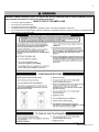
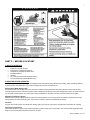
IF THE INFORMATION IN THIS MANUAL IS NOT FOLLOWED EXACTLY, A FIRE OR EXPLOSION MAY RESULT, CAUSING
PROPERTY DAMAGE, PERSONAL INJURY, OR LOSS OF LIFE. DO NOT STORE GASOLINE OR OTHER FLAMMABLE VAPORS
AND LIQUIDS IN THE VICINITY OF THIS OR ANY OTHER APPLIANCE.
WHAT TO DO IF YOU SMELL GAS
Do not try to light any appliance.
Do not touch any electrical switch.
Do not use any phone in your building.
Immediately call your gas supplier from a neighbor’s phone. Follow the gas supplier’s instructions.
If you cannot reach your gas supplier, call the fire department. Installation and service must be provided by a qualified installer,
service agency, or the gas supplier.
WHL-019 REV. 12.17.14
3
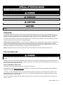
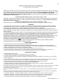
The following defined terms are used throughout this manual to bring attention to the presence of hazards of various risk
levels, or to important product information.
DANGER indicates an imminently hazardous situation which, if not avoided, will result in death or serious injury.
WARNING indicates a potentially hazardous situation which, if not avoided, could result in death or serious injury.
CAUTION indicates a potentially hazardous situation which, if not avoided, may result in minor or moderate injury.
CAUTION used without the safety alert symbol indicates a potentially hazardous situation which, if not avoided, may result in property
damage.
FOREWORD
This manual is intended to be used in conjunction with other literature provided with the Commercial Gas-Fired Water Heater. This
includes all related control information. It is important that this manual, all other documents included with this system, and additional
publications including the National Fuel Gas Code, ANSI Z223.1-2002, be reviewed in their entirety before beginning any work.
Installation should be made in accordance with the regulations of the Authority Having Jurisdiction, local code authorities, and utility
companies which pertain to this type of water heating equipment.
Authority Having Jurisdiction (AHJ) – The Authority Having Jurisdiction may be a federal, state, local government, or individual such
as a fire chief, fire marshal, chief of a fire prevention bureau, labor department or health department, building official or electrical
inspector, or others having statutory authority. In some circumstances, the property owner or his/her agent assumes the role, and at
government installations, the commanding officer or departmental official may be the AHJ.
NOTE: Westinghouse reserves the right to modify product technical specifications and components without prior notice.
FOR THE INSTALLER
This manual must only be used by a qualified heating installer/service technician. Read and understand all instructions in this manual
before installing. Perform steps in the order given. Failure to comply will result in substantial property damage, severe personal injury,
or death.
This water heater must be installed by qualified and licensed personnel. The installer should be guided by the instructions furnished
with the heater, and with local codes and utility company requirements. In the absence of local codes, preference should be given to the
National Fuel Gas Code, ANSI Z223.1-2002.
INSTALLATIONS MUST COMPLY WITH:
Local, state, provincial, and national codes, laws, regulations and ordinances.
The latest version of the National Fuel Gas Code, ANSI Z223.1, from American Gas Association Laboratories, 8501 East Pleasant
Valley Road, Cleveland, OH 44131.
In Canada – CGA No. B149 (latest version), from Canadian Gas Association Laboratories, 55 Scarsdale Road, Don Mills, Ontario,
Canada M3B 2R3. Also, Canadian Electrical Code C 22.1, from Canadian Standards Association, 5060 Spectrum Way, Suite 100,
Mississauga, Ontario, Canada L4W 5N6.
Code for the installation of Heat Producing Appliances (latest version), from American Insurance Association, 85 John Street, New
York, NY 11038.
WHL-019 REV. 12.17.14
4
The latest version of the National Electrical Code, NFPA No. 70.
NOTE: The gas manifold and controls met safe lighting and other performance criteria when undergoing tests specified in ANSI
Z21.10.3 – latest edition.
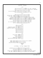
TABLE OF CONTENTS
PART 1 – GENERAL SAFETY INFORMATION ..........................................................................................................................5
A. PRECAUTIONS .......................................................................................................................................................................... 5
B. IMPROPER COMBUSTION ........................................................................................................................................................ 6
C. GAS ............................................................................................................................................................................................ 6
D. WHEN SERVICING THE HEATER............................................................................................................................................. 6
E. HEATER WATER........................................................................................................................................................................ 6
PART 2 – BEFORE YOU START ................................................................................................................................................7
A. WHAT’S IN THE BOX ................................................................................................................................................................. 7
B. HOW THE HEATER OPERATES ............................................................................................................................................... 7
C. OPTIONAL EQUIPMENT ........................................................................................................................................................... 8
PART 3 – PREPARE WATER HEATER LOCATION ..................................................................................................................8
A. BEFORE LOCATING THE HEATER .......................................................................................................................................... 9
B. LEVELING .................................................................................................................................................................................. 9
C. CLEARANCES FOR SERVICE ACCESS ................................................................................................................................. 10
D. RESIDENTIAL GARAGE INSTALLATION ................................................................................................................................ 10
E. EXHAUST VENT AND INTAKE PIPE ....................................................................................................................................... 10
1. DIRECT VENT INSTALLATION OF EXHAUST VENT AND INTAKE PIPE ......................................................................................................... 11
2. INDOOR COMBUSTION AIR INSTALLATION IN CONFINED OR UNCONFINED SPACE ................................................................................ 11
F. PREVENT COMBUSTION AIR CONTAMINATION .................................................................................................................. 11
G. REMOVING A HEATER FROM A COMMON VENT SYSTEM................................................................................................. 12
H. WATER CHEMISTRY ............................................................................................................................................................... 13
PART 4 – HEATER PIPING ....................................................................................................................................................... 16
A. GENERAL PIPING INFORMATION .......................................................................................................................................... 16
B. SCALDING ................................................................................................................................................................................ 17
C. TEMPERATURE AND PRESSURE RELIEF VALVE................................................................................................................ 17
D. BACKFLOW PREVENTER ....................................................................................................................................................... 17
E. POTABLE EXPANSION TANK ................................................................................................................................................. 17
F. WATER PIPING ........................................................................................................................................................................ 18
G. AUXILIARY CONNECTIONS ................................................................................................................................................... 18
H. PIPING DIAGRAMS .................................................................................................................................................................. 19
PART 5 – VENTING, COMBUSTION AIR AND CONDENSATE REMOVAL............................................................................ 27
A. GENERAL ................................................................................................................................................................................. 27
B. APPROVED MATERIALS FOR EXHAUST VENT AND INTAKE PIPE .................................................................................... 28
C. REQUIREMENTS FOR INSTALLATION IN CANADA .............................................................................................................. 28
D. EXHAUST VENT AND INTAKE PIPE LOCATION.................................................................................................................... 29
E. EXHAUST VENT AND INTAKE PIPE SIZING .......................................................................................................................... 30
WHL-019 REV. 12.17.14
5
F. LONGER VENT RUNS ............................................................................................................................................................. 30
G. EXHAUST VENT AND INTAKE PIPE INSTALLATION ............................................................................................................ 31
H. VENTING DRAWINGS ............................................................................................................................................................. 32
1. DIRECT VENT INSTALLATION OF EXHAUST VENT AND INTAKE PIPE ......................................................................................................... 32
2. VENTING THROUGH AN EXISTING SYSTEM .................................................................................................................................................. 35
3. INDOOR COMBUSTION AIR INSTALLATION IN CONFINED OR UNCONFINED SPACE ................................................................................ 37
I. CONDENSATE REMOVAL SYSTEM ........................................................................................................................................ 39
PART 6 – WIRING ..................................................................................................................................................................... 39
A. LINE VOLTAGE INPUT ............................................................................................................................................................ 39
B. LINE VOLTAGE CONDENSATE OUTPUT ............................................................................................................................... 40
C. LOW VOLTAGE OUTDOOR SENSOR INPUT ......................................................................................................................... 40
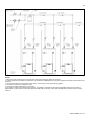
D. INTERNAL WIRING DIAGRAM ................................................................................................................................................ 41
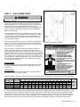
PART 7 – GAS CONNECTIONS ............................................................................................................................................... 43
A. GAS PIPING ............................................................................................................................................................................. 43
B. GAS TABLE .............................................................................................................................................................................. 43
C. GAS VALVE .............................................................................................................................................................................. 44
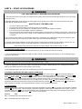
PART 8 – START-UP PROCEDURE ......................................................................................................................................... 45
A. OPERATING INSTRUCTIONS ................................................................................................................................................. 45
B. OVERALL WATER HEATER AND CONTROL OPERATION ................................................................................................... 45
C. STATUS MENU ........................................................................................................................................................................ 45
D. OUTDOOR RESET................................................................................................................................................................... 46
E. TEST MODE ............................................................................................................................................................................. 47
F. MAINTENANCE ........................................................................................................................................................................ 47
PART 9 – SHUTDOWN.............................................................................................................................................................. 48
A. SHUTDOWN PROCEDURE ..................................................................................................................................................... 48
B. VACATION PROCEDURE ........................................................................................................................................................ 48
C. FAILURE TO OPERATE ........................................................................................................................................................... 48
PART 10 – TROUBLESHOOTING ............................................................................................................................................ 48
A. ERROR CODE .......................................................................................................................................................................... 48
B. HEATER ERROR...................................................................................................................................................................... 48
C. LOCKOUT ................................................................................................................................................................................ 48
PART 11 - MAINTENANCE ....................................................................................................................................................... 53
MAINTENANCE NOTES ........................................................................................................................................................................................ 56
CUSTOMER INSTALLATION RECORD FORM ..................................................................................................................................................... 57
Gas Fired Commercial Water Heater Limited Warranty .......................................................................................................................................... 58
PART 1 – GENERAL SAFETY INFORMATION
A. PRECAUTIONS
This water heater is for indoor installations only. Clearance to combustible materials: 0” top, bottom, sides and back. Unit must have
room for service: 24” front and 12” sides are minimum recommended service clearances. (A combustible door or removable panel is
WHL-019 REV. 12.17.14
6
acceptable front clearance.) This water heater has been approved for closet installation, and installation on combustible flooring. Do not
install this water heater directly on carpeting. Use only Category IV vent systems.
INSTALLER – Read all instructions in this manual before installing. Perform steps in the order given.
USER – This manual is for use only by a qualified heating installer/service technician. Have this heater serviced/inspected by a
qualified service technician annually.
FAILURE TO ADHERE TO THE GUIDELINES ON THIS PAGE AND HAVE THIS HEATER SERVICED/INSPECTED ANNUALLY
CAN RESULT IN SUBSTANTIAL PROPERTY DAMAGE, SEVERE PERSONAL INJURY, OR DEATH.
If the heater is exposed to the following, do not operate until all corrective steps have been made by a qualified serviceman:
1. FIRE
2. DAMAGE
3. WATER
Any claims for damage or shortage in shipment must be filed immediately against the transportation company by the consignee.
DO NOT USE THIS APPLIANCE IF ANY PART HAS BEEN SUBMERGED IN WATER. Immediately call a qualified service technician.
The appliance MUST BE replaced if it has been submerged. Attempting to operate an appliance that has been submerged could create
numerous harmful conditions, such as a potential gas leakage causing a fire and/or explosion, or the release of mold, bacteria, or other
harmful particulates into the air. Operating a previously submerged appliance could result in property damage, severe personal injury,
or death.
NOTE: Appliance damage due to flood or submersion is considered an Act of God, and IS NOT covered under product warranty.
B. IMPROPER COMBUSTION
Do not obstruct the flow of combustion and ventilating air. Adequate air is necessary for safe operation. Failure to keep the vent and
combustion air intake clear of ice, snow, or other debris could result in property damage, serious personal injury, or death.
C. GAS
Should overheating or gas supply fail to shut off, turn off the manual
gas control valve to the water heater.
D. WHEN SERVICING THE HEATER
To avoid electric shock, disconnect electrical supply before
performing maintenance.
To avoid severe burns, allow heater to cool.
E. HEATER WATER
Do not use petroleum-based cleaning or sealing compounds
in a heater system. Gaskets and seals in the system may be
damaged. This can result in substantial property damage.
Do not use “homemade cures” or “heater patent medicines”.
Substantial property damage, damage to heater, and/or
serious personal injury may result.
WHL-019 REV. 12.17.14
7
PART 2 – BEFORE YOU START
A. WHAT’S IN THE BOX
Also included with the heater:
Intake PVC Tee with Screens
Exhaust PVC Coupling with Screens
Temperature and Pressure Relief Valve
Installation Manual
Warranty
LP Conversion Kit (Natural Gas Models Only)
Two Threaded Caps (WGCM Models Only)
B. HOW THE HEATER OPERATES
Modulation Condensing Technology is an intelligent system that delivers highly efficient water heating, while maximizing efficiency
by measuring the data parameters of your water heating system. Some of its features are:
Stainless Steel Water Storage Tank
The stainless steel water storage tank has a combustion chamber submerged into the tank water. When the water heater is fired,
combustion gases heat the combustion chamber walls, transferring heat directly into the surrounding water. These hot gases are blown
into secondary heat exchanger coils, where more heat is transferred into the water, removing even more heat from the gases.
Modulating Combustion System
Modulation during water heating operation is based on tank temperature. The control monitors the system to regulate burner output
during operation to match system demand. This increase in efficiency allows for substantial fuel savings.
Gas Valve
The gas valve senses suction from the blower, allowing gas to flow only if the gas valve is energized and combustion air is flowing.
Upper Supply Tank Sensor
This sensor monitors the upper portion water temperature (system supply) of the water heater. The control module adjusts the burner
firing rate so the outlet water temperature meets the set point.
WHL-019 REV. 12.17.14
8
Lower Return Tank Sensor
This sensor monitors the lower portion of the water heater inlet water temperature (system return). The control module reduces or
increases input, depending on how close the water temperature is to the outlet water temperature set point.
Control
The integrated control system monitors upper and lower water temperature and regulates fan speed to regulate the unit’s energy
output. This allows the unit to deliver the required amount of heated energy and nothing more.
Burner
Constructed of high grade stainless steel, the burner uses pre-mixed air and gas and provides a wide range of firing rates.
Condensate Drain Connection
This is a condensing high efficiency water heater, and therefore has a condensate removal system. Condensate is nothing more than
water vapor, derived from combustion products and similar to an automobile when it is initially started. It is very important that the
condensate line slopes away from the water heater and down to a suitable inside drain.
If the condensate outlet on the heater is lower than the drain, you must use a condensate removal pump (kit p/n 554200 available from
Westinghouse.) In addition, local authorities may require a condensate neutralizer to neutralize the condensate. Condensate
neutralizers are made up of lime crystals, marble or phosphate chips. Neutralizers can be installed in the field by the installer and
purchased from Westinghouse (p/n 7450P-212).
It is also very important not to expose the condensate line to freezing temperatures or any type of blockage. Plastic tubing must be the
only material used for the condensate line. Steel, brass, copper or other materials will be subject to corrosion or deterioration. A second
vent may be necessary to prevent condensate line vacuum lock on a long horizontal run. Also, an increase in pipe size may be
necessary to allow condensate to drain properly. Support of the condensation line may be necessary to avoid blockage of the
condensate flow.
Spark Ignition
The burner flame is ignited by applying high voltage to the system spark electrode. This causes a spark from electrode to ground.
C. OPTIONAL EQUIPMENT
Below is a list of optional equipment available from Westinghouse:
3” Stainless Steel Outside Termination Vent Kit (V1000)
4” Stainless Steel Outside Termination Vent Kit (V2000)
2” PVC Concentric Vent Kit (Part # KGAVT0501CVT)
3" PVC Concentric Vent Kit (Part # KGAVT0601CVT)
3” Polypro Vent Kit (Part # 8400P-001)
3” Polypro Pipe (33’ length Part # 8400P-002, 49.5’ length Part # 8400P-003)
PC Connection Kit (Part # 7250P-320)
Condensate Neutralizer (Part # 7450P-212)
Outdoor Sensor (Part # 7250P-319)
Sanitizer Booster Kit (Part # VSBK-1200)
PART 3 – PREPARE WATER HEATER LOCATION
Carefully consider installation when determining heater location. Please read the entire manual before attempting installation. Failure to
properly take factors such as heater venting, piping, condensate removal, and wiring into account before installation could result in
wasted time, money, and possible property damage and personal injury.
WHL-019 REV. 12.17.14
9
A. BEFORE LOCATING THE HEATER
Incorrect ambient conditions can lead to damage to the heating system and put safe operation at risk. Ensure that the heater installation
location adheres to the information included in this manual. Failure to do so could result in property damage, serious personal injury, or
death.
Failure of heater or components due to incorrect operating conditions IS NOT covered by product warranty.
1. Installation Area (Mechanical Room) Operating Conditions
o
o
o
o
Ensure ambient temperatures are higher than 32 F/0 C and lower than 104 F/40 C.
Prevent the air from becoming contaminated by the products, places, and conditions listed in this manual, Part 3, Section F.
Avoid continuously high levels of humidity
Never close existing ventilation openings
Ensure a minimum 1” clearance around hot water and exhaust vent pipes
The service life of the heater’s exposed metallic surfaces, such as the casing, as well as internal surfaces, such as the heat exchanger,
are directly influenced by proximity to damp and salty marine environments. In such areas, higher concentration levels of chlorides from
sea spray coupled with relative humidity can lead to degradation of the heat exchanger and other heater components. In these
environments, heaters must not be installed using direct vent systems which draw outdoor air for combustion. Such heaters must be
installed using room air for combustion. Indoor air will have a much lower relative humidity and, hence, potential corrosion will be
minimized.
This heater is certified for indoor installations only. Do not install the heater outdoors. Failure to install this heater indoors could result in
substantial property damage, severe personal injury, or death.
2. Check for nearby connections to:
System water piping
Venting connections
Gas supply piping
Electrical power
Condensate drain
3. Check area around heater. Remove any combustible materials, gasoline, and other flammable liquids.
Failure to keep heater area clear and free of combustible materials, liquids, and vapors can result in substantial property damage,
severe personal injury, or death.
4. Gas control system components must be protected from dripping water during operation and service.
5. If the heater is to replace an existing heater, check for and correct any existing system problems, such as:
System leaks
Location that could cause the system and heater to freeze and leak.
Incorrectly-sized expansion tank
6. Clean and flush system when reinstalling a heater.
NOTE: When installing in a zero clearance location, it may not be possible to read or view some product labeling. It is recommended to
make note of the heater model and serial number.
B. LEVELING
In order for the condensate to properly flow out of the collection system, the area where you locate the heater must be level. Location
must also fully support the weight of the filled water heater.
WHL-019 REV. 12.17.14
10
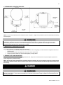
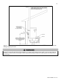
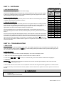
C. CLEARANCES FOR SERVICE ACCESS
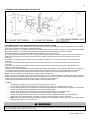
Figure 1 – Minimum Service Clearances
NOTE: If you do not provide the minimum clearances shown in Figure 1, it might not be possible to service the heater without removing
it from the space.
The space must be provided with combustion/ventilation air openings correctly sized for all other appliances located in the same space
as the heater. The heater cover must be securely fastened to prevent the heater from drawing air form the heater room. This is
particularly important if the heater is in a room with other appliances. Failure to comply with the above warnings could result in
substantial property damage, severe personal injury, or death.
D. RESIDENTIAL GARAGE INSTALLATION
PRECAUTIONS
If the heater is located in a residential garage, per ANSI Z223.1:
Mount the bottom of the heater a minimum of 18” above the floor of the garage, to ensure the burner and ignition devices are
well off the floor.
When raising the heater, fully support the entire bottom of the water heater.
Locate or protect the heater so it cannot be damaged by a moving vehicle.
E. EXHAUST VENT AND INTAKE PIPE
The heater is rated ANSI Z21.10.3 Category IV (pressurized vent, likely to form condensate in the vent) and requires a special vent
system designed for pressurized venting.
NOTE: The venting options described here (and further detailed in Venting, Part 5 in this manual) are the lone venting options
approved for this water heater. Failure to vent the water heater in accordance with the provided venting instructions will void
the warranty.
Failure to vent the water heater properly will result in serious personal injury or death.
Vents must be properly supported. Heater exhaust and intake connections are not designed to carry heavy weight. Vent support
brackets must be within 1’ of the heater and the balance at 4’ intervals. Heater must be readily accessible for visual inspection for the
first 3’ from the heater.
WHL-019 REV. 12.17.14
11
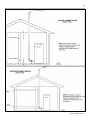
1. DIRECT VENT INSTALLATION OF EXHAUST VENT AND INTAKE PIPE
If installing a direct vent option, combustion air must be drawn from the outdoors directly into the water heater intake, and exhaust must
terminate outside. There are three basic direct vent options detailed in this manual: 1. Side Wall Venting, 2. Roof Venting, and 3.
Unbalanced Venting.
Be sure to locate the heater such that the exhaust vent and intake piping can be routed through the building and properly terminated.
Different vent terminals can be used to simplify and eliminate multiple penetrations in the building structure (see Optional Equipment in
Venting Section). The exhaust vent and intake piping lengths, routing and termination methods must all comply with the methods and
limits given in the Venting section, Part 5 of this manual.
When installing a combustion air intake from outdoors, care must be taken to utilize uncontaminated combustion air. To prevent
combustion air contamination, see Table 1 – Contaminant Table.
2. INDOOR COMBUSTION AIR INSTALLATION IN CONFINED OR UNCONFINED SPACE
This heater requires fresh, uncontaminated air for safe operation and must be installed in a mechanical room where there is adequate
combustion and ventilating air. NOTE: To prevent combustion air contamination, see Table 1 – Contaminant Table.
Combustion air from the indoor space can be used if the space has adequate area or when air is provided through a duct or louver to
supply sufficient combustion air based on the water heater input. Never obstruct the supply of combustion air to the water heater.
If the water heater is installed in areas where indoor air is contaminated (see Table 1) it is imperative that the water heater be installed
as direct vent so that all combustion air is taken directly from the outdoors into the water heater intake connection.
Unconfined space is space with volume greater than 50 cubic feet per 1,000 Btu/hour (4.8 cubic meters per kW) of the total input
rating of all fuel-burning appliances installed in that space. Rooms connected directly to this space, through openings not furnished with
doors, are considered part of the space. See Figure 20, p. 38 for details.
Confined space is space with volume less than 50 cubic feet per 1,000 Btu/hour (4.8 cubic meters per kW) of the total input rating of
all fuel-burning appliances installed in that space. Rooms connected directly to this space, through openings not furnished with doors,
are considered part of the space.
When drawing combustion air from inside a conventionally constructed building to a confined space, such space should be provided
with two permanent openings: one located 6” (15 cm) below the space ceiling, the other 6” (15cm) above the space floor. Each opening
2
should have a free area of one square inch per 1,000 Btu/hr (22cm /kW) of the total input of all appliances in the space, but not less
2
than 100 square inches (645cm ).
If the confined space is within a building of tight construction, air for combustion must be obtained from the outdoors as outlined in the
Venting section, Part 5 of this manual.
When drawing combustion air from the outside into the mechanical room, care must be taken to provide adequate freeze protection.
Do not attempt to vent this water heater by any means other than those described in this manual. Doing so will void the warranty, and
may result in severe personal injury or death.
Failure to provide an adequate supply of fresh combustion air can cause poisonous flue gases to enter living space, resulting in severe
personal injury or death. To prevent combustion air contamination, see Table 1.
F. PREVENT COMBUSTION AIR CONTAMINATION
Install intake piping for the heater as described in the Venting Section. Do not terminate exhaust in locations that can allow
contamination of intake air.
Ensure that the intake air will not contain any of the contaminants below. Contaminated air will damage the heater, resulting in possible
substantial property damage, severe personal injury, or death. For example, do not pipe intake near a swimming pool. Also, avoid areas
subject to exhaust fumes from laundry facilities. These areas always contain contaminants.
WHL-019 REV. 12.17.14
12
PRODUCTS TO AVOID
Spray cans containing fluorocarbons
Permanent wave solutions
Chlorinated waxes/cleaners
Chlorine-based swimming pool chemicals
Calcium chloride used for thawing
Sodium chloride used for water softening
Refrigerant leaks
Paint or varnish removers
Hydrochloric or Muriatic acid
Cements and glues
Antistatic fabric softeners used in clothes dryers
Chlorine-type bleaches, laundry detergents, and cleaning solvents
Adhesives used to fasten building products
AREAS LIKELY TO HAVE CONTAMINANTS
Dry cleaning/laundry areas and establishments
Swimming pools
Metal fabrication plants
Beauty shops
Refrigeration repair shops
Photo processing plants
Auto body shops
Plastic manufacturing plants
Furniture refinishing areas and establishments
New building construction
Remodeling areas
Garages and workshops
Table 1 – Contaminant Table
NOTE: DAMAGE TO THE HEATER CAUSED BY EXPOSURE TO CORROSIVE VAPORS IS NOT COVERED BY WARRANTY.
(Refer to the limited warranty for complete terms and conditions).
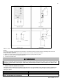
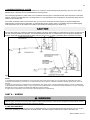
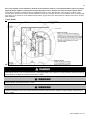
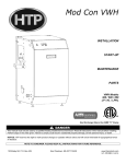
G. REMOVING A HEATER FROM A COMMON VENT SYSTEM
Do not install the heater into a common vent with any other appliance. This will cause flue gas spillage or appliance malfunction,
resulting in possible substantial property damage, severe personal injury, or death.
Failure to follow all instructions can result in flue gas spillage and carbon monoxide emissions, causing severe personal injury or death.
When removing an existing heater, follow the steps below.
1. Seal any unused openings in the common venting system.
2. Visually inspect the venting system for proper size and horizontal
pitch to determine if there is blockage, leakage, corrosion or other
deficiencies that could cause an unsafe condition.
3. If practical, close all building doors, windows and doors between the
space in which the water heater remains connected to the common
venting system and other spaces in the building. Turn on clothes dryers
and any appliances not connected to the common venting system. Turn
on any exhaust fans, such as range hoods and bathroom exhausts, at
maximum speed. Do not operate a summer exhaust fan. Close all
fireplace dampers.
4. Place in operation the appliance being inspected. Follow the lighting
instructions. Adjust the thermostat so the appliance will operate
continuously.
5. Test for spillage at the draft hood relief opening after 5 minutes of
main burner operation. Use the flame of a match or candle or smoke
from a cigarette.
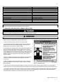
Figure 2 - CO Warning Label
6. After it has been determined that each appliance remaining connected to common venting system properly vents when tested as
outlined, return doors, windows, exhaust fans, fireplace dampers and any other gas burning appliance to their previous condition of use.
7. Any improper operation of the common venting system should be corrected to conform to the National Fuel Gas Code, ANSI Z223.1.
When resizing any portion of the common venting system, the system should approach the minimum size as determined using the
appropriate tables in Appendix G in the National Fuel Gas Code, ANSI Z 223.1.
WHL-019 REV. 12.17.14
13
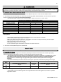
H. WATER CHEMISTRY
Chemical imbalance of the water supply may affect efficiency and cause severe damage to the water heater and associated equipment.
Westinghouse recommends having water quality professionally analyzed to determine whether it is necessary to install a water
softener. It is important that the water chemistry on both the domestic hot water and central heating sides are checked before installing
the water heater, as water quality will affect the reliability of the system. Failure of a heat exchanger due to lime scale build-up on the
heating surface, low pH, or other chemical imbalance IS NOT covered by the warranty.
o
Operating temperatures above 135 F will further accelerate the build-up of lime scale on the heating surface and may shorten the
service life of the water heater. Failure of a heat exchanger due to lime scale build-up on the heating surface, low pH, or other chemical
imbalance IS NOT covered by the warranty.
Outlined below are water quality parameters which need to be met in order for the system to operate efficiently for many years.
Water Hardness
Water hardness is mainly due to the presence of calcium and magnesium salts dissolved in water. The concentration of these salts is
expressed in mg/L, ppm, or grains per gallon as a measure of relative water hardness. Grains per gallon is the common reference
measurement used in the U.S. water heater industry. Hardness expressed as mg/L or ppm may be divided by 17.1 to convert to grains
per gallon. Water may be classified as very soft, slightly hard, moderately hard, or hard based on its hardness number. The minerals in
the water precipitate out as the water is heated and cause accelerated lime scale accumulation on a heat transfer surface. This lime
o
scale build-up may result in premature failure of the heat exchanger. Operating temperatures above 135 F will further accelerate the
build-up of lime scale on the heating surface and may shorten the service life of the water heater.
Water that is classified as hard and very hard must be softened to avoid heat exchanger failure. See below for further information about
water hardness.
CLASSIFICATION
Soft
Slightly Hard
Moderately Hard
Hard
Very Hard
MG/L OR PPM
0 – 17.1
17.1 – 60
60 – 120
120 – 180
180 and over
GRAINS/GAL
0-1
1 – 3.5
3.5 – 7.0
7.0 – 10.5
10.5 and over
If the hardness of the water exceeds the maximum level of 7 grains per gallon, water should be softened to a hardness level no lower
than 5 grains per gallon. Water softened as low as 0 to 1 grain per gallon may be under-saturated with respect to calcium carbonate,
resulting in water that is aggressive and corrosive.
pH of Water
pH is a measure of relative acidity, neutrality or alkalinity. Dissolved minerals and gases affect water pH. The pH scale ranges from 0 to
14. Water with a pH of 7.0 is considered neutral. Water with a pH lower than 7 is considered acidic. Water pH higher than 7 is
considered alkaline. A neutral pH (around 7) is desirable for most potable water applications. Corrosion damage and heater failures
resulting from water pH levels of lower than 6 or higher than 8 ARE NOT covered by the warranty. The ideal pH range for water
used in a storage tank or a water heater system is 7.2 to 7.8.
Total Dissolved Solids
Total Dissolved Solids (TDS) is a measurement of all minerals and solids dissolved in a water sample. The concentration of total
dissolved solids is usually expressed in parts per million (ppm).
Water with a high TDS concentration will greatly accelerate lime and scale formation in the hot water system. Most high TDS
concentrations precipitate out of the water when heated. This can generate a scale accumulation on the heat transfer surface that will
greatly reduce the service life of a water heater. This scale accumulation can also impede the ability of the heat exchanger to transfer
heat into the water. A heat exchanger damaged or blocked by lime/scale accumulation must be replaced.
The manufacturer of the water heater has no control of water quality, especially TDS levels in your system. Total dissolved solids in
excess of 2,000 ppm will accelerate lime and scale formation in the heat exchanger. Heat exchanger failure due to total dissolved solids
in excess of 2,000 ppm is a non-warrantable condition. Failure of a water heater due to lime scale build up on the heating surface
IS NOT covered by the warranty.
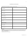
Hardness: 7 grains
Chloride levels: 100 ppm
pH levels: 6-8
TDS: 2000 ppm
Sodium: 20 mGL
WHL-019 REV. 12.17.14
14
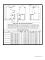
Figure 3 – *ALL DIMENSIONS ARE APPROXIMATE
WHL-019 REV. 12.17.14
15
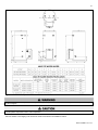
Figure 4 - Phoenix Multi Fit Specifications and Dimensions
UNCRATING HEATER – Any claims for damage or shortage in shipment must be filed immediately against the transportation company
by the consignee.
o
COLD WEATHER HANDLING – If the heater has been stored in a very cold location (BELOW 0 F) before installation, handle with care
until the plastic components come to room temperature.
Remove all sides of the shipping crate to allow the heater to be lifted into its installation location.
WHL-019 REV. 12.17.14
16
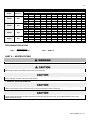
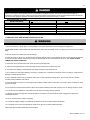
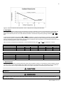
PERFORMANCE SPECIFICATIONS FOR ALL MODELS
BTUH
Efficiency
100,000
96%
130,000
96%
160,000
96%
199,000
96%
(°F)
(°C)
GPH
GPM
LPH
LPM
GPH
GPM
LPH
LPM
GPH
GPM
LPH
LPM
GPH
GPM
LPH
LPM
40
22
298
5
1128
18.8
384
6.4
1454
24.25
470
7.8
1779
29.7
582
9.7
2203
36.7
50
28
240
4
908
15.1
309
5.2
1170
19.5
378
6.3
1431
23.9
468
7.8
1772
29.5
60
33
202
3.4
765
12.75
260
4.3
984
16.4
317
5.3
1200
20
392
6.5
1484
24.7
Temperature Rise
70
80
90
39
44
50
173
152
136
2.9
2.5
2.25
655
575
515
10.9
9.6
8.6
222
195
175
3.7
3.25
2.9
840
738
662
14
12.3
11
271
238
213
4.5
4
3.6
1026
901
806
17.1
15
13.4
335
294
263
5.6
4.9
4.4
1268
1113
996
21.1
18.6
16.6
100
56
123
2
466
7.8
158
2.6
598
10
192
3.2
727
12.1
237
4
897
15
110
61
110
1.8
416
6.9
141
2.4
534
8.9
173
2.9
655
10.9
213
3.6
806
13.4
120
67
101
1.7
382
6.4
130
2.2
492
8.2
159
2.7
602
10
196
3.3
742
12.4
130
72
94
1.6
356
5.9
120
2
454
7.6
147
2.5
556
9.3
181
3
685
11.4
140
78
88
1.5
333
5.6
112
1.9
424
7
137
2.3
519
8.7
169
2.8
640
10.7
Table 2 – Recovery on rating plate is based at 94% thermal efficiency at 70o Fahrenheit rise, as required by ANSI
PERFORMANCE EQUATIONS
GPM =
Rated Input x .9
o
Temp Rise ( F) x 500
GPH =
GPM x 60
PART 4 – HEATER PIPING
Failure to follow the instructions in this section WILL VOID the warranty and may result in property damage, serious injury, or death.
Never use dielectric unions or galvanized steel fittings when connecting to a stainless steel storage tank or heater. Use only copper or
brass fittings. Teflon thread sealant must be used on all connections.
DO NOT pipe this water heater with black iron, galvanized steel, steel, or lead pipe. Doing so will result in premature product failure and
property damage, and WILL VOID the product warranty.
A. GENERAL PIPING INFORMATION
Use two wrenches when tightening water piping at heater. Use one wrench to prevent the heater return or supply line from turning.
Failure to prevent piping connections from turning could cause damage to heater components.
The heater control module uses temperature sensors to provide both high limit protection and modulating temperature control. The
control module also provides low water protection by sensing the water level in the tank. Some codes/jurisdictions may require
additional external controls.
WHL-019 REV. 12.17.14
17
B. SCALDING
APPROXIMATE TIME / TEMPERATURE RELATIONSHIPS IN SCALDS
o
120 F
More than 5 minutes
o
125 F
1 ½ to 2 minutes
o
130 F
About 30 seconds
o
135 F
About 10 seconds
o
140 F
Less than 5 seconds
o
145 F
Less than 3 seconds
o
150 F
About 1 ½ seconds
o
155 F
About 1 second
Table 3
This heater can deliver scalding water. Be careful whenever using hot water to avoid
scalding injury. Certain appliances, such as dishwashers and automatic clothes
washers may require increased water temperature. By setting the thermostat on this
heater to obtain the increased water temperature required by these appliances, you
may create the potential for scald injury.
To protect against injury, you should install a mixing valve in the water system. This
valve will reduce point of discharge temperature by mixing cold and hot water in
branch supply lines. Such valves are available from your local plumbing supplier.
Table 3 details the relationship of water temperature and time with regard to scald
injury and may be used as a guide in determining the safest water temperature for
your applications.
C. TEMPERATURE AND PRESSURE RELIEF VALVE
To avoid water damage or scalding due to relief valve operation:
Discharge line must be connected to relief valve outlet and run to a safe place of disposal. Terminate the discharge line in a
manner that will prevent possibility of severe burns or property damage should the relief valve discharge.
Discharge line must be as short as possible and the same size as the valve discharge connection throughout its entire length.
Discharge line must pitch downward from the valve and terminate at least 6” above the floor drain, making discharge clearly
visible.
o
The discharge line shall terminate plain, not threaded, with a material serviceable for temperatures of 375 F or greater.
Do not pipe discharge to any location where freezing could occur.
No shutoff valve may be installed between the relief valve and heater or in the discharge line. Do not plug or place any
obstruction in the discharge line.
Test the operation of the relief valve after filling and pressurizing the system by lifting the lever. Make sure the valve
discharges freely. If the valve fails to operate correctly, immediately replace with a new properly rated relief valve.
Test T&P valve at least once annually to ensure the waterway is clear. If valve does not operate, turn the heater “off” and call
a plumber immediately.
Take care whenever operating relief valve to avoid scalding injury or property damage.
FAILURE TO COMPLY WITH THE ABOVE GUIDELINES COULD RESULT IN FAILURE OF RELIEF VALVE OPERATION,
RESULTING IN POSSIBILITY OF SUBSTANTIAL PROPERTY DAMAGE, SEVERE PERSONAL INJURY, OR DEATH.
Do not thread a cap or plug into the relief valve under any circumstances! Explosion and property damage, serious injury, or death may
result.
D. BACKFLOW PREVENTER
Use a backflow preventer specifically designed for water heater installations. This valve should be installed on the cold water fill supply
line per local codes.
E. POTABLE EXPANSION TANK
A potable hot water expansion tank is required to offset heated water expansion. In most city plumbing systems, the water meter has a
no return or back flow device built into the system to prevent back flowing of water into city mains. Some local codes require back flow
preventers on all incoming water supplies. The hot water expansion tank must be listed for potable water use. The expansion tank
should be located on the cold inlet piping close to the water heater.
WHL-019 REV. 12.17.14
18
EXPANSION TANK AND MAKE-UP WATER
1. Ensure that the expansion tank is sized to correctly handle heater and system water volume and temperature.
Undersized expansion tanks cause system water to be lost from the relief valve, causing make-up water to be added. Eventual heater
failure can result due to excessive make-up water addition. SUCH FAILURE IS NOT COVERED BY WARRANTY.
2. The expansion tank must be located as shown in the Heater Piping Details, or following recognized design methods. See expansion
tank manufacturer’s instructions for details.
The expansion tank must be suitable for hot potable water.
F. WATER PIPING
Never use dielectric unions or galvanized steel fittings on any domestic water or auxiliary connections. Use only copper or brass fittings.
Thread sealant must be used on all connections.
The domestic water connections must be installed in accordance to all local and national plumbing codes, or any applicable standard
which prevails. The inlet and outlet ports are 1" on 55 gallon models, and 1 ½” on 80 and 119 gallon models.
On the cold inlet, install a 1" brass tee on 55 gallon models, or a 1 ½" tee on 80 and 119 gallon models. On the run of the 1" brass tee,
install a 1" brass drain cock or equivalent with pipe sealant compound. In the branch of the 1" or a 1 ½" brass tee, install a copper male
adapter to match your copper plumbing system. For convenience, you may install a sweat shut off valve and a union in the cold inlet
piping to ease future servicing. If there is a back flow preventer or any type of a no return valve in the system, you must install an
additional tee here, suitable for a potable hot water expansion tank.
In the hot outlet, install a suitable adapter to match the copper tubing of the plumbing system. A thermal trap or heat trap loop may be
installed here to provide additional energy savings and prevent the thermal siphoning of domestic hot water.
G. AUXILIARY CONNECTIONS
The auxiliary connections are additional connections for air handlers, plate exchangers, or other devices that supply hot water. These
connections must be installed in accordance with all local and national codes or any applicable standard that prevails. Auxiliary
connections are 1" on all models. Never use dielectric unions or galvanized steel fittings. Use only copper or brass fittings. Sealant must
be used on all connections. The top port is the supply outlet and the bottom port is the return inlet.
Never connect auxiliary connections to any system that uses glycol or other solutions formulated for hydronic systems. These auxiliary
connections are to be used only in a potable water system. Failure to follow this warning could result in serious injury or death.
WHL-019 REV. 12.17.14
19
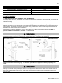
H. PIPING DIAGRAMS
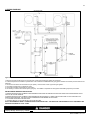
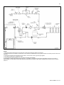
Figure 5 – Water Heater With Air Handler - NOTES:
1. Minimum pipe size should match unit connection size. Upsize pipe accordingly if greater flow is required.
2. A thermal expansion tank suitable for potable water must be sized and installed within this piping system between the backflow preventer and the cold
water inlet.
3. Gas line must be rated to the unit maximum input capacity. Unit must have 10 feet of pipe after gas regulator.
4. All circulators should have an integral flow check.
5. Check with air handler manufacturer for proper sizing.
6. This drawing is meant to demonstrate system piping only. The installer is responsible for all equipment and detailing required by local codes.
NOTES FOR AIR HANDLER APPLICATION:
1. MASSACHUSETTS STATE PLUMBING CODE REQUIRES A DISTANCE NO GREATER THAN 50 FEET FROM THE WATER HEATER TO THE
FAN COIL IN THE AIR HANDLER.
2. MASSACHUSETTS STATE PLUMBING CODE REQUIRES AN ELECTRONICALLY TIMED CIRCULATOR PUMP TO ACTIVATE EVERY SIX
HOURS FOR 60 SECONDS. THIS CIRCULATOR IS REQUIRED TO BE BRONZE OR STAINLESS.
3. ALL WATER PIPING MUST BE INSULATED.
4. YOU MUST INSTALL A VACUUM RELIEF VALVE PER 248 CMR.
NOTE: THIS DRAWING IS MEANT TO DEMONSTRATE SYSTEM PIPING ONLY. THE INSTALLER IS RESPONSIBLE FOR ALL EQUIPMENT AND
DETAILING REQUIRED BY LOCAL CODES.
An ASSE 1017 thermostatic mixing valve MUST be installed when using outdoor reset. Failure to do so could result in substantial
property damage, serious injury, or death.
WHL-019 REV. 12.17.14
20
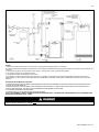
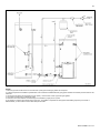
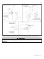
Figure 6 – Water Heater with Air Handler on Side
NOTES:
1. Minimum pipe size should match unit connection size. Upsize pipe accordingly if greater flow is required.
2. A thermal expansion tank suitable for potable water must be sized and installed within this piping system between the backflow preventer and the cold
water inlet.
3. Gas line must be rated to the unit maximum input capacity. Unit must have 10 feet of pipe after gas regulator.
4. All circulators should have an integral flow check.
5. Check with air handler manufacturer for proper sizing.
6. This drawing is meant to demonstrate system piping only. The installer is responsible for all equipment and detailing required by local codes. In
Massachusetts, you must install a vacuum relief valve per 248 CMR. With air handlers, outdoor reset is available with an outdoor sensor. See Part 8,
Section D.
NOTES FOR AIR HANDLER APPLICATION:
1. MASSACHUSETTS STATE PLUMBING CODE REQUIRES A DISTANCE NO GREATER THAN 50 FEET FROM THE WATER HEATER TO THE
FAN COIL IN THE AIR HANDLER.
2. MASSACHUSETTS STATE PLUMBING CODE REQUIRES AN ELECTRONICALLY TIMED CIRCULATOR PUMP TO ACTIVATE EVERY SIX
HOURS FOR 60 SECONDS. THIS CIRCULATOR IS REQUIRED TO BE BRONZE OR STAINLESS.
3. ALL WATER PIPING MUST BE INSULATED.
4. YOU MUST INSTALL A VACUUM RELIEF VALVE PER 248 CMR.
NOTE: THIS DRAWING IS MEANT TO DEMONSTRATE SYSTEM PIPING ONLY. THE INSTALLER IS RESPONSIBLE FOR ALL EQUIPMENT AND
DETAILING REQUIRED BY LOCAL CODES.
An ASSE 1017 thermostatic mixing valve MUST be installed when using outdoor reset. Failure to do so could result in substantial
property damage, serious injury, or death.
WHL-019 REV. 12.17.14
21
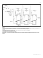
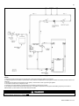
Figure 7 – Reverse Manifold and Piping
NOTES:
1. Minimum pipe size should match unit connection size. Upsize pipe accordingly if greater flow is required.
2. A thermal expansion tank suitable for potable water must be sized and installed within this piping system between the backflow preventer and the cold
water inlet.
3. Gas line must be rated to the unit maximum input capacity. Unit must have 10 feet of pipe after gas regulator.
4. All circulators should have an integral flow check.
5. Check with air handler manufacturer for proper sizing.
6. This drawing is meant to demonstrate system piping only. The installer is responsible for all equipment and detailing required by local codes. In
Massachusetts, you must install a vacuum relief valve per 248 CMR. With air handlers, outdoor reset is available with an outdoor sensor. See Part 8,
Section D.
WHL-019 REV. 12.17.14
22
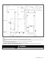
Figure 8 –Closed Loop with Radiant Heating
NOTES:
1. Minimum pipe size should match unit connection size. Upsize pipe accordingly if greater flow is required.
2. A thermal expansion tank suitable for potable water must be sized and installed within this piping system between the backflow preventer and the cold
water inlet.
3. Gas line must be rated to the unit maximum input capacity. Unit must have 10 feet of pipe after gas regulator.
4. All circulators should have an integral flow check.
5. Check with brazed plate manufacturer for correct plate connections and orientation.
6. This drawing is meant to demonstrate system piping only. The installer is responsible for all equipment and detailing required by local codes. In
Massachusetts, you must install a vacuum relief valve per 248 CMR. With air handlers, outdoor reset is available with an outdoor sensor. See Part 8,
Section D.
WHL-019 REV. 12.17.14
23
Figure 9 – Water Heater With Storage Tank
NOTES:
1. Minimum pipe size should match unit connection size. Upsize pipe accordingly if greater flow is required.
2. A thermal expansion tank suitable for potable water must be sized and installed within this piping system between the backflow preventer and the cold
water inlet.
3. Gas line must be rated to the unit maximum input capacity. Unit must have 10 feet of pipe after gas regulator.
4. All circulators should have an integral flow check.
5. Drains and check valve between unit and storage tank will assist in purging air from system.
6. This drawing is meant to demonstrate system piping only. The installer is responsible for all equipment and detailing required by local codes. In
Massachusetts, you must install a vacuum relief valve per 248 CMR.
WHL-019 REV. 12.17.14
24
Figure 10 – Water Heater with Recirculation Line and Thermostatic Mixing Valve Piping
NOTES:
1. Minimum pipe size should match unit connection size. Upsize pipe accordingly if greater flow is required.
2. A thermal expansion tank suitable for potable water must be sized and installed within this piping system between the backflow preventer and the cold
water inlet.
3. Gas line must be rated to the unit maximum input capacity. Unit must have 10 feet of pipe after gas regulator.
4. All circulators should have an integral flow check.
5. Drains and check valve between unit and storage tank will assist in purging air from system.
6. This drawing is meant to demonstrate system piping only. The installer is responsible for all equipment and detailing required by local codes. In
Massachusetts, you must install a vacuum relief valve per 248 CMR.
An ASSE 1017 thermostatic mixing valve MUST be installed when using outdoor reset. Failure to do so could result in substantial
property damage, serious injury, or death.
WHL-019 REV. 12.17.14
25
Figure 11 –Multi Fit Model with Storage Tank and Thermostatic Mixing Valve
NOTES:
1. Minimum pipe size should match unit connection size. Upsize pipe accordingly if greater flow is required.
2. A thermal expansion tank suitable for potable water must be sized and installed within this piping system between the backflow preventer and the cold
water inlet.
3. Gas line must be rated to the unit maximum input capacity. Unit must have 10 feet of pipe after gas regulator.
4. All circulators should have an integral flow check.
5. Drains and check valve between unit and storage tank will assist in purging air from system.
6. This drawing is meant to demonstrate system piping only. The installer is responsible for all equipment and detailing required by local codes. In
Massachusetts, you must install a vacuum relief valve per 248 CMR.
An ASSE 1017 thermostatic mixing valve MUST be installed when using outdoor reset. Failure to do so could result in substantial
property damage, serious injury, or death.
WHL-019 REV. 12.17.14
26
Figure 12 - Reverse Manifold and Piping Diagram for Multi Fit Model
NOTES:
1. Minimum pipe size should match unit connection size. Upsize pipe accordingly if greater flow is required.
2. A thermal expansion tank suitable for potable water must be sized and installed within this piping system between the backflow preventer and the cold
water inlet.
3. Gas line must be rated to the unit maximum input capacity. Unit must have 10 feet of pipe after gas regulator.
4. All circulators should have an integral flow check.
5. Check with air handler manufacturer for proper sizing.
6. This drawing is meant to demonstrate system piping only. The installer is responsible for all equipment and detailing required by local codes. In
Massachusetts, you must install a vacuum relief valve per 248 CMR. With air handlers, outdoor reset is available with an outdoor sensor. See Part 8,
Section D.
WHL-019 REV. 12.17.14
27
PART 5 – VENTING, COMBUSTION AIR AND CONDENSATE REMOVAL
The heater must be vented as detailed in this Venting Section. Ensure exhaust vent and intake piping complies with these instructions
regarding vent system. Inspect finished exhaust vent and intake piping thoroughly to ensure all joints are well secured, airtight, and
comply with all applicable code requirements, as well as with the instructions provided in this manual. Failure to properly install the vent
system will result in severe personal injury or death.
A. GENERAL
This heater is certified as a “Category IV” appliance, and requires a special venting system. The vent system will operate with a positive
pressure in the pipe. Exhaust gases must be piped directly outdoors using the vent materials and rules outlined in these instructions.
Do not connect vent connectors serving appliances vented by natural draft into any portion of mechanical draft systems operating under
positive pressure. Follow the venting instructions below carefully. Failure to do so will result in substantial property damage, severe
personal injury, or death.
1. Installation should be made in accordance with the regulations of the
Authority Having Jurisdiction, local code authorities, and utility companies
which pertain to this type of water heating equipment.
2. Install the venting system in accordance with these instructions and with
the National Fuel Gas Code, ANSI Z223.1/NFPA 54, CAN/CGA B149,
and/or applicable provisions of local building codes.
3. This water heater must be vented with materials, components, and
systems listed and approved for Category IV appliances.
Exhaust vent and intake pipes are to be piped separately. This heater
cannot share a common exhaust or intake with multiple appliances. Failure
to follow this instruction will result in substantial property damage, severe
personal injury, or death.
NOTE: To avoid contamination often contained in indoor air, it is best to pipe
all intake combustion air directly to the outdoors.
NOTE: If exhaust vent pipe system passes through an unheated space,
such as an alcove or attic, the space must be heated or the pipe must be insulated. The insulation must have an R value sufficient to
prevent freezing of the condensate.
Improper seating of vent pipe gaskets can cause eventual gasket failure and exhaust gas leakage. Ensure the exhaust vent pipe is
properly beveled and seated before insertion into the flue adapter. Failure to do so could result in property damage, severe personal
injury, or death.
Due to the extreme flammability of most glues, cements, solvents, and primers used to join plastic exhaust vent and intake pipes,
explosive solvent vapors must be cleared from all vent piping before start-up. Avoid using excess cement or primer, as this may pool in
the vent pipes. Vent assemblies should be allowed to cure for a period of at least 8 hours before powering a connected appliance.
Failure to follow these instructions will result in substantial property damage, severe personal injury, or death. It is the installers’
responsibility to understand the hazards associated with explosive solvents and take the necessary precautions to avoid these risks.
WHL-019 REV. 12.17.14
28
B. APPROVED MATERIALS FOR EXHAUST VENT AND INTAKE PIPE
Item
Exhaust vent or Intake
pipe and fittings
Pipe cement/primer
APPROVED EXHAUST VENT AND INTAKE PIPE MATERIAL
Standards for Installation in:
Material
United States
Canada
PVC schedule 40/80
ANSI/ASTM D1785
PP, CPVC, and PVC venting must be ULCPVC-DWV*
ANSI/ASTM D2665
S636 Certified. IPEX is an approved
manufacturer in Canada, supplying vent
CPVC schedule 40/80
ANSI/ASTM F441
material listed to ULC-S636.
Polypropylene
ULCS636
Certified for Category IV and
Certified for Category IV and direct vent
Stainless Steel AL29-4C
direct vent appliance venting
appliance venting
PVC
ANSI/ASTM D2564
IPEX System 636 Cements & Primers
CPVC
ANSI/ASTM F493
The exhaust and intake components installed with this heater must be used for near heater piping BEFORE transitioning to the
approved materials listed above. DO NOT REMOVE these installed components. Doing so WILL VOID heater warranty.
PVC/CPVC pipe and fittings of the same diameter are considered interchangeable.
DO NOT use Foam Core Pipe in any portion of the exhaust piping from this water heater.
DO NOT connect PVC/CPVC to PP without an approved vent connector.
When installing AL29-4C vent piping, install a PVC-to-stainless adapter at the heater vent connection, and at the termination
when using an PVC termination kit. DO NOT mix AL-29-4C piping from different manufacturers unless using adapters
specifically designed for the purpose by the manufacturer.
*PVC-DWV for air intake applications ONLY.
Failure to follow these directions will result in substantial property damage, severe personal injury, or death.
Table 4 – Approved Materials for Exhaust Vent and Intake Pipe
DO NOT mix components from different venting systems. The vent system could fail, causing leakage of flue products into the living
space. Use only the approved pipe and fitting materials, and primer and cement specifically designed for the material used, as listed in
Table 4. Failure to do so could result in property damage, severe personal injury, or death.
Exhaust vent adaptors are not designed as load-bearing devices, and must not be used to support exhaust vent piping. All vent pipes
must be properly connected, supported, and the exhaust must be pitched a minimum of ¼” per foot back to the heater to allow drainage
of condensate. Failure to properly support vent piping and follow the information in this statement could result in product damage,
severe personal injury, or death.
NOTE: The use of double-wall vent or insulated material for the combustion air inlet pipe is recommended in cold climates to prevent
the condensation of airborne moisture in the incoming combustion air.
o
o
High heat sources (sources generating heat 100 F / 37 C or greater, such as stove pipes, space heaters, etc.) may damage plastic
components of the water heater as well as plastic vent pipe materials. Such damages ARE NOT covered by warranty. It is
recommended to keep a minimum clearance of 8” from high heat sources. Observe heat source manufacturer instructions, as well as
local, state, provincial, and national codes, laws, regulations and ordinances when installing this water heater and related components
near high heat sources.
C. REQUIREMENTS FOR INSTALLATION IN CANADA
1. Installations must be made with a vent pipe system certified to ULC-S636. IPEX is an approved vent manufacturer in Canada
supplying vent material listed to ULC-S636. Additionally you may use AL29-4C stainless steel venting to comply with Canadian
requirements.
2. The first three (3) feet of vent pipe from the water heater flue outlet must be readily accessible for visual inspection.
3. The components of the certified vent system must not be interchanged with other vent systems or unlisted pipe / fittings.
Cellular foam core piping may be used on air inlet piping only.
You must not use “B” vent in an exhaust application. “B” vent is for intake applications ONLY. Using “B” vent in an exhaust application
will result in serious injury or death.
WHL-019 REV. 12.17.14
29
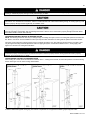
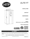
D. EXHAUST VENT AND INTAKE PIPE LOCATION
Figure 13 – ANSI Z223.1 / NFPA 54 for US and CAN/CSA B149.1 for Canada – Exit Terminals for Direct-Vent Venting Systems
DETERMINE EXHAUST VENT AND INTAKE PIPE LOCATION – FIGURE 13 NOTES:
A. Provide a minimum of 1 foot clearance from the bottom of the exhaust vent and intake pipe above the expected snow accumulation
level. Snow removal may be necessary to maintain clearance.
B. Provide a minimum of 1 foot distance from exhaust vent termination to any door, operable window, or gravity intake into any building.
C. Provide a minimum of 1 foot distance from exhaust vent termination to any permanently closed door or window.
D. Provide a minimum of 4 feet vertical clearance from the exhaust vent to all roof overhangs.
E. Locating exhaust vent termination near roof overhangs will result in the formation of icicles in freezing weather, and could result in
blockage of the exhaust vent. To prevent icicles from forming, maintain 4 feet vertical clearance from the exhaust vent to all roof
overhangs.
F. Provide 4 feet clearance from the outside corner of vertical walls, chimneys, etc., as well as horizontal corners created by roof
overhangs.
G. Provide 6 feet clearance from the inside corner of vertical walls, chimneys, etc., as well as horizontal corners created by roof
overhangs.
H. Provide 4 feet clearance from center line within a height of 15 feet above electrical meters, gas meters, gas regulators, relief
equipment, exhaust fans and inlets.
I. Provide 4 feet horizontal clearance from electrical meters, gas meters, gas regulators, relief equipment, exhaust fans and inlets. In no
case shall the exit terminal be above or below the aforementioned equipment unless the 4 foot horizontal distance is maintained.
J. This water heater vent system shall terminate at least 3 feet (0.9 m) above any forced air intake located within 10 ft (3 m).
NOTE: This does not apply to the combustion air intake of a direct-vent appliance.
K. When venting with a two pipe system, maximum distance between exhaust vent and intake pipe is 6 feet (1.8 m). Minimum distance
between exhaust vent and intake pipe on single direct vented appliance is 10” (0.255 m) center-to-center. Minimum distance between
exhaust vents and intake pipes on multiple water heaters is 10” (0.255 m) center-to-center.
L. When adjacent to a public walkway, locate exit terminal at least 7 feet above grade.
In addition:
Total length of vent piping shall not exceed the limits specified in this manual.
The vent piping for this direct vented appliance is approved for zero clearance to combustible construction.
The flue products coming from the exhaust vent will create a large plume when the water heater is in operation. Avoid venting
in areas that will affect neighboring buildings or be considered objectionable.
DO NOT locate exhaust vent or intake pipe in a parking area where machinery may damage the pipe.
DO NOT locate the exhaust vent or intake pipe terminals under a porch, balcony, or veranda.
Avoid terminating exhaust vents near shrubs, air conditioners, or other objects that will obstruct the exhaust stream.
DO NOT vent over a public walkway. Condensate could drip or freeze and create a nuisance or hazard.
NOTE: Due to potential moisture build-up, sidewall venting may not be the preferred venting option. Carefully consider venting
installation and location to save time and cost.
The building owner is responsible for keeping the exhaust and intake terminations free of snow, ice, or other potential blockages, as
well as scheduling routine maintenance. Failure to keep the vent piping terminations clear and properly maintain the heater could result
in property damage, severe personal injury, or death.
WHL-019 REV. 12.17.14
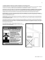
30
For each floor containing bedroom(s), a carbon monoxide detector and alarm shall be placed in the living area outside the bedrooms,
as well as in the room that houses the heater. Detectors and alarms shall comply with NFPA 720 (latest edition). Failure to comply with
requirements for detectors and alarms could result in property damage, severe personal injury, or death.
E. EXHAUST VENT AND INTAKE PIPE SIZING
1. The exhaust vent and intake pipe size is 2" for the 100 and 130kBTU models and 3" for the 160 and 199kBTU models.
2. The maximum total equivalent length of 2” exhaust vent and intake pipe must not exceed 85 feet. The total maximum equivalent
length of 3” exhaust vent and intake pipe must not exceed 200 feet.
a. The equivalent length of elbows, tees, and other fittings are listed in the Friction Loss Table, Table 5:
FITTINGS OR PIPING
90 DEGREE ELBOW*
45 DEGREE ELBOW
COUPLING
AIR INLET TEE
STRAIGHT PIPE
CONCENTRIC VENT KIT
V500 2” VENT KIT
V1000 3” VENT KIT
V2000 4” VENT KIT
FRICTION LOSS EQUIVALENT IN PIPING AND FITTINGS
EQUIVALENT FEET
2”
3”
5’
5’
3’
3’
0’
0’
0’
0’
1’
1’
3’
3’
1’
N/A
N/A
1’
N/A
1’
4”
3’
1’
0’
0’
1’
N/A
N/A
1’
1’
Table 5 - *Friction loss for long radius elbow is 1 foot less. NOTE: Consult Polypropylene venting instructions for friction loss and pressure
drop equivalents.
b. For example: If the exhaust vent has two 90° elbows and 10 feet of PVC pipe we will calculate:
Exhaust Vent Equivalent Length = (2x5) + 10 = 20 feet.
Further, if the intake pipe has two 90° elbows, one 45° elbow and 10 feet of PVC pipe, the following calculation applies:
Intake Pipe Equivalent Length = (2x5) + 3 + 10 = 23 feet.
Finally, if a concentric vent kit is used we find:
Total Equivalent Length = 20 + 23 + 3 = 46 feet.
The total equivalent length is 46 feet which is well below the maximum of 85 feet.
3. The minimum total equivalent length is 16 equivalent feet.
Failure to provide a minimum total vent length of 16 equivalent feet could result in property damage and improper product operation.
F. LONGER VENT RUNS
The maximum total equivalent length can be extended by increasing the diameter of both exhaust vent and intake pipe equally.
However, the transitions should begin a minimum of 15 total equivalent feet from the water heater.
a. The maximum total equivalent length for increased diameter vent pipes is 125 feet for 2” transitioning to 3” pipe
(this number includes the minimum 15 total equivalent feet necessary for transition), and 200 maximum total
equivalent feet for 3” transitioning to 4” pipe (including the minimum 15 total equivalent feet necessary for
transition).
b. Transitions should always be made in vertical sections of pipe to prevent the condensate from pooling in the vent pipe.
kBTU
MAXIMUM TOTAL EQUIVALENT LENGTH AT
STANDARD VENT CONNECTION
100
85’ @ 2”
130
160
200’ @ 3”
199
Table 6 – Vent Sizing – Diameter and Length
REDUCING
COUPLING
MAXIMUM TOTAL EQUIVALENT LENGTH AT
MAXIMUM INCREASED VENT SIZE
3” X 2”
125’ at 3”
4” X 3”
200’ at 4”
c. If the transition occurs at a distance greater than 15 equivalent feet from the water appliance, the maximum equivalent
length will be reduced.
WHL-019 REV. 12.17.14
31
Total maximum equivalent length of increased diameter exhaust vent and intake pipe must not exceed the lengths defined in this
manual. 125 maximum total equivalent feet for 2” increased to 3” diameter vent pipe; 200 maximum total equivalent feet for 3”
increased to 4” diameter vent pipe. Failure to keep the total equivalent length below the maximum lengths determined in this manual
will result in faulty appliance operation, substantial property damage, serious personal injury, or death.
TRANSITION POINT (FT. FROM
TEL OF OVERSIZED VENT PIPE (FT.)*
MAXIMUM TEL OF ALL VENT PIPE (FT.)
WATER APPLIANCE)
15
95
125
20
77-1/2
117-1/2
25
60-1/2
110-1/2
30
43
103
35
26
96
40
8-1/2
88-1/2
NONE
0
85
Table 7 – TEL = Total Equivalent Length *Oversized vent pipe diameter is 1” or greater than factory supplied connection.
G. EXHAUST VENT AND INTAKE PIPE INSTALLATION
All joints of positive pressure vent systems must be sealed completely to prevent leakage of flue products into living space.
1. Use only solid PVC or CPVC pipe, or a Polypropylene vent system approved for use with Category IV appliances.
FOAM CORE PIPING IS NOT APPROVED FOR EXHAUST VENT APPLICATIONS. Foam core piping may be used on air inlet piping
only.
2. Remove all burrs and debris from joints and fittings.
3. When using PVC or CPVC pipe, all joints must be properly cleaned, primed, and cemented. Use only cement and primer approved
for use with the pipe material. Cement must conform to ASTM D2564 for PVC and ASTM F493 for CPVC pipe. NOTE: DO NOT
CEMENT POLYPROPYLENE PIPE.
4. Ensure the vent is located where it will not be exposed to prevailing winds.
5. In all roof venting applications, exhaust discharge must point away from the pitch of the roof.
6. To prevent water leakage, install adequate roof flashing where the pipe enters the roof.
7. Do not locate vent over public walkways, driveways, or parking lots. Condensate could drip and freeze, resulting in a slip hazard or
damage to vehicles and machinery.
8. Due to potential moisture build-up, sidewall venting may not be the preferred venting option. To save time and cost, carefully
consider venting installation and location.
9. Horizontal lengths of exhaust vent must slope back towards the water heater not less than ¼" per foot to allow condensate to drain
from the vent pipe.
10. The exhaust vent must terminate where vapors cannot make accidental contact with people or pets, or damage shrubs or plants.
11. In vacant chimney applications, install and seal a rain cap over existing chimney openings.
12. All piping must be fully supported. Use pipe hangers at a minimum of 4 foot intervals to prevent sagging of the pipe where
condensate may form.
13. Do not use the heater to support any piping.
14. A screened straight coupling is provided with the heater for use as an outside exhaust termination.
15. A screened inlet air tee is provided with the heater to be used as an outside intake termination.
Table 8 lists optional intake air/exhaust vent termination:
WHL-019 REV. 12.17.14
32
DESCRIPTION
2” PVC CONCENTRIC VENT TERMINATION KIT
3” PVC CONCENTRIC VENT TERMINATION KIT
2” STAINLESS STEEL VENT TERMINATION KIT
3” STAINLESS STEEL VENT TERMINATION KIT
4” STAINLESS STEEL VENT TERMINATION KIT
3” POLYPRO VENT KIT
STOCK CODE
KGAVT0501CVT
KGAVT0601CVT
V500
V1000
V2000
8400P-001
Table 8
H. VENTING DRAWINGS
1. DIRECT VENT INSTALLATION OF EXHAUST VENT AND INTAKE PIPE
If installing a direct vent option, combustion air must be drawn from the outdoors directly into the water heater intake, and exhaust must
terminate outside. There are three basic direct vent options detailed in this manual: 1. Side Wall Venting, 2. Roof Venting, and 3.
Unbalanced Venting.
Be sure to locate the heater such that the exhaust vent and intake piping can be routed through the building and properly terminated.
Different vent terminals can be used to simplify and eliminate multiple penetrations in the building structure (see Optional Equipment in
Venting Section). The exhaust vent and intake piping lengths, routing and termination methods must all comply with the methods and
limits given in the Venting section, Part 5 of this manual.
When installing a combustion air intake from outdoors, care must be taken to utilize uncontaminated combustion air. NOTE: To
prevent combustion air contamination, see Table 1 – Contaminant Table.
Take extra precaution to adequately support the weight of vent pipes terminating through the roof. Failure to properly support roof
terminated vent piping could result in property damage, serious personal injury, or death due to flue gas leakage.
Figure 14 – Two Pipe Roof and Sidewall Venting with Included Equipment (Tee and Coupling) - NOTE: These drawings are
meant to demonstrate system venting only. The installer is responsible for all equipment and detailing required by local
codes.
All vent pipes must be glued, properly supported, and the exhaust must be pitched a minimum of ¼” per foot back to the heater to allow
drainage of condensate. When placing support brackets on vent piping, the first bracket must be within 1 foot of the water heater and
the balance at 4 foot intervals on the vent pipe. Heater venting must be readily accessible for visual inspection for the first three feet
from the heater.
WHL-019 REV. 12.17.14
33
Figure 15 – Venting with Optional Kits (NOT INCLUDED WITH THE WATER HEATER) NOTE: These drawings are meant to
demonstrate system venting only. The installer is responsible for all equipment and detailing required by local codes.
All vent pipes must be glued, properly supported, and the exhaust must be pitched a minimum of ¼” per foot back to the heater to allow
drainage of condensate. When placing support brackets on vent piping, the first bracket must be within 1 foot of the water heater and
the balance at 4 foot intervals on the vent pipe. Heater venting must be readily accessible for visual inspection for the first three feet
from the heater.
WHL-019 REV. 12.17.14
34
Figure 16 – LP-179-F - NOTE: This drawing is meant to demonstrate system venting only. The installer is responsible for all equipment and
detailing required by local codes.
All vent pipes must be glued, properly supported, and the exhaust must be pitched a minimum of ¼” per foot back to the heater to allow
drainage of condensate. When placing support brackets on vent piping, the first bracket must be within 1 foot of the water heater and
the balance at 4 foot intervals on the vent pipe. Heater venting must be readily accessible for visual inspection for the first three feet
from the heater.
WHL-019 REV. 12.17.14
35
Figure 17 – Horizontal Venting - NOTE: Drawing is meant to demonstrate system venting ONLY.
NOTES:
A. For every 1” of overhang, the exhaust vent must be located 1” vertical below overhang (overhang means top of building structure and not two
adjacent walls [corner of building]).
B. Typical installations require 12” minimum separation between bottom of exhaust outlet and top of air intake.
C. Maintain 12” minimum clearance above highest anticipated snow level or grade (whichever is greater).
D. Minimum 12” between vents when installing multiple vents.
E. 12” minimum beyond air intake.
All vent pipes must be glued, properly supported, and the exhaust must be pitched a minimum of ¼” per foot back to the heater to allow
drainage of condensate. When placing support brackets on vent piping, the first bracket must be within 1 foot of the water heater and
the balance at 4 foot intervals on the vent pipe. Heater venting must be readily accessible for visual inspection for the first three feet
from the heater.
2. VENTING THROUGH AN EXISTING SYSTEM
This heater may be vented through an existing unused vent system. The inner diameter of the existing vent system is utilized for the
combustion air source. Two methods have been approved for such venting: Concentric Venting Through an Existing System and
Venting as a Chase.
VENT / AIR INLET SIZE
2”
3”
4”
MINIMUM EXISTING VENT / CHASE SIZE
4”
5”
7”
Table 9 – Minimum Existing Vent / Chase Sizing
WHL-019 REV. 12.17.14
36
Do not install the heater into a common existing vent with any other appliance. This will cause flue gas spillage or heater malfunction,
resulting in substantial property damage, severe personal injury, or death.
Contractors must check state and local codes before installing through an existing vent opening. State and local codes always take
precedence over manufacturer’s instructions. Failure to check state and local codes before installing through an existing opening could
result in property damage and add significantly to installation costs.
If an existing venting system is converted for use with this heater, the installer must ensure that the existing venting system is clean and
free from particulate contamination that could damage the heater. Failure to do so could result in property damage and heater failure.
Such failure IS NOT covered under warranty.
CONCENTRIC VENTING THROUGH AN EXISTING SYSTEM
NOTE: The following instructions refer only to venting through an existing vent system, and not to venting with optional concentric vent
kits. Refer to Concentric Vent Kit installation manual (LP-166) for further information on venting with the optional concentric vent kits.
Concentric venting through an existing system must run vertically through the roof. See Table 9 for proper minimum vent sizing. Use
only the approved venting materials specified in Table 4 for piping the system. All instructions listed in Part 5 - Venting apply. See
Figures 18-1 and 18-2 for venting demonstrations.
The upper and lower vent terminations as well as all joints in the venting system must be properly sealed to ensure that all combustion
air is drawn properly and exhaust does not leak from the system. Failure to properly seal the venting system will result in property
damage, severe personal injury, or death.
CHASE VENTING THROUGH AN EXISTING SYSTEM
When venting as a chase, follow all instructions included in Part 5 – Venting of this manual, as well as the previous Concentric Venting
section. See Figure 18-3 for chase venting demonstration.
Figures 18 – 1, 18 – 2 Concentric Venting Through an Existing System, 18 – 3 Chase Venting Through an Existing System NOTE: This drawing
is meant to demonstrate system venting only. The installer is responsible for all equipment and detailing required by local codes.
WHL-019 REV. 12.17.14
37
3. INDOOR COMBUSTION AIR INSTALLATION IN CONFINED OR UNCONFINED SPACE
This heater requires fresh, uncontaminated air for safe operation and must be installed in a mechanical room where there is adequate
combustion and ventilating air. NOTE: To prevent combustion air contamination, see Table 1 – Contaminant Table.
Combustion air from the indoor space can be used if the space has adequate area or when air is provided through a duct or louver to
supply sufficient combustion air based on the water heater input. Never obstruct the supply of combustion air to the water heater.
If the water heater is installed in areas where indoor air is contaminated (see Figure 19) it is imperative that the water heater be
installed as direct vent so that all combustion air is taken directly from the outdoors into the water heater intake connection.
Unconfined space is space with volume greater than 50 cubic feet per 1,000 Btu/hour (4.8 cubic meters per kW) of the total input
rating of all fuel-burning appliances installed in that space. Rooms connected directly to this space, through openings not furnished with
doors, are considered part of the space.
Confined space is space with volume less than 50 cubic feet per 1,000 Btu/hour (4.8 cubic meters per kW) of the total input rating of
all fuel-burning appliances installed in that space. Rooms connected directly to this space, through openings not furnished with doors,
are considered part of the space.
When drawing combustion air from inside a conventionally constructed building to a confined space, such space should be provided
with two permanent openings: one located 6” (15 cm) below the space ceiling, the other 6” (15cm) above the space floor. Each opening
2
should have a free area of one square inch per 1,000 Btu/hr (22cm /kW) of the total input of all appliances in the space, but not less
2
than 100 square inches (645cm ).
If the confined space is within a building of tight construction, air for
combustion must be obtained from the outdoors as outlined in the Venting
section of this manual. See Figure 20.
Figure 19 – LP-325-X
WHL-019 REV. 12.17.14
38
Figure 20
WHL-019 REV. 12.17.14
39
I. CONDENSATE REMOVAL SYSTEM
NOTE: Check with your local gas company to determine if combustion condensate disposal is permitted in your area. In the state of
Massachusetts, condensate must be neutralized before entering a drain.
This condensing high efficiency water heater has a condensate removal system. Condensate is water vapor derived from combustion
products, similar to an automobile when it is initially started. It is very important that the condensate line is sloped down away from the
heater and to a suitable drain.
If the heater condensate outlet is lower than the drain, you must use a condensate removal pump (kit p/n 554200 available from
Westinghouse). If required by local authorities, a condensate filter of lime crystals, marble, or phosphate chips will neutralize slightly
acidic condensate. This can be installed in the field and purchased from Westinghouse (p/n 7450P-212).
The condensate line must remain unobstructed. If allowed to freeze in the line or obstructed in any other manner, condensate can exit
from the water heater tee, resulting in potential water damage to property. When installing a condensate pump, select one approved for
use with condensing heaters and furnaces. The condensate pump should have an overflow switch to prevent property damage from
spillage. Condensate from the heater will be slightly acidic (pH from 3.2 to 4.5). Install a neutralizing filter if required by local codes.
Figure 21 – LP-179-K
NOTES:
1. Condensate line must be pitched at least ¼” per foot to properly drain. If this cannot be done, or a very long length of condensate hose is used,
increase the condensate line to a minimum of 1” ID and place a tee in the line after the condensate neutralizer to properly reduce vacuum lock in the
drain line.
2. Plastic pipe should be the only material used for condensate line. Steel, brass, copper, and other metals will be subject to corrosion or deterioration.
3. NEVER install condensate lines outside. It is very important that the condensate line is not exposed to freezing temperatures or any type of blockage.
Damages due to frozen or blocked condensate lines ARE NOT covered by warranty.
4. Support of the condensate line may be necessary to avoid blockage of the condensate flow.
PART 6 – WIRING
To avoid electrical shock, turn off all power to the heater prior to opening an electrical box within the unit. Ensure the power remains off
while any wiring connections are being made. Failure to follow these instructions could result in component or product failure, serious
injury, or death. Such product failure IS NOT covered by warranty.
A. LINE VOLTAGE INPUT
The heater must be wired to a 120 volt circuit by a qualified electrician. It is recommended that the heater be wired on its own circuit to
minimize the possibility of circuit failure due to outside causes. The heater requires a maximum of 8 amps at 120 volts in use.
WHL-019 REV. 12.17.14
40
B. LINE VOLTAGE CONDENSATE OUTPUT
The heater has the capability of supplying power to a condensate pump. The connection is 120 VAC +/- 10% at a max of 2 amps.
Power is supplied to the pump only when the heater is connected to power, and the power switch is in the on position.
C. LOW VOLTAGE OUTDOOR SENSOR INPUT
The heater has the capability of an outdoor reset. Connecting an outdoor sensor allows the heater to operate at optimum efficiency.
HTP offers an outdoor sensor, p/n 7250P-319.
The outdoor sensor must be a 12K NTC sensor. Use a minimum 22 AWG wire for runs of 100 feet or less and minimum 18 AWG wire
for runs up to 150 feet. Instructions are included with the outdoor sensor to correctly mount the sensor on the exterior surface of the
building. It is preferable to mount the sensor on the north side in an area that will not be affected by direct sunlight but will be exposed
to varying weather conditions. Connect the outdoor sensor to terminals marked “Outdoor”.
It is of extreme importance that this unit be properly grounded. It is very important that the building system ground is inspected by a
qualified electrician prior to making this connection. Electrical power must only be turned on when the heater is completely filled with
cold water.
Figure 22 – Low Voltage Wiring
Label all wires prior to disconnecting them when servicing the heater. Wiring errors can cause improper and dangerous operation.
Failure to follow these instructions may result in property damage or personal injury.
WHL-019 REV. 12.17.14
41
D. INTERNAL WIRING DIAGRAM
Figure 23 – Wiring Diagram
WHL-019 REV. 12.17.14
42
Figure 24 – LP-179-L
WHL-019 REV. 12.17.14
43
PART 7 – GAS CONNECTIONS
Failure to follow all precautions could result in fire, explosion,
severe injury or death!
The gas supply shall have a maximum inlet pressure of less than 14"
water column (350 mm), ½ pound pressure (3.5 kPa), and a minimum
of 3.5" water column. The entire piping system, gas meter and
regulator must be sized properly to prevent pressure drop greater than
0.5" WC as stated in the National Fuel Gas Code. This information is
listed on the rating plate.
It is very important that you are connected to the type of gas as noted
on the rating plate: "LP" for liquefied petroleum, propane gas, or "Nat"
for natural or city gas. All gas connections must be approved by the
local gas supplier or utility, in addition to the governing authority, prior
to turning the gas supply on.
Do not remove the adaptor in Figure 25! It is mandatory that this fitting is
used for connection to a field fabricated drip leg per the National Fuel
Gas Code. You must ensure that the entire gas line to the connection at
the water heater is no smaller than ¾".
Figure 25 – Gas Connection - LP-179-Q
Once all inspections have been performed, the piping must be leak
tested. If the leak test requirement is a higher test pressure than the
maximum gas inlet pressure, you must isolate the heater from the gas line
to continue leak testing. To do this, you must turn off the factory and fieldinstalled gas cocks. This will minimize the possibility of damaging the gas
valve. Failure to do so may damage the gas valve. In the event the gas
valve is exposed to a pressure greater than ½ PSI, 14" water column, the
gas valve must be replaced. Never use an open flame (match, lighter,
etc.) to check gas connections.
A. GAS PIPING
Run the gas supply line in accordance with all applicable codes. Locate
and install manual shutoff valves in accordance with local and state
requirements.
B. GAS TABLE
Refer to the table below to size the supply piping to minimize pressure
drop between meter or regulator and unit.
Maximum capacity of pipe in cubic feet of gas per hour for gas pressures of .5 psi or less and a pressure drop of .3 inch water column.
Nominal Iron
Pipe Size (In.)
Internal
Dia. (In.)
10
278
¾
.824
520
1
1.049
1,050
1¼
1.380
1,600
1½
1.610
Table 10 – Source – ANSI Z223.1
Length of Pipe (Feet)
20
190
350
730
1,100
30
152
285
590
890
40
130
245
500
760
50
115
215
440
670
60
105
195
400
610
70
96
180
370
560
80
90
170
350
530
90
84
160
320
490
100
79
150
305
460
125
72
130
275
410
150
64
120
250
380
175
59
110
225
350
200
55
100
210
320
BTU’s
Per Hour
x
1,000
It is recommended that a soapy solution be used to detect leaks. Bubbles will appear on the pipe to indicate a leak is present. The gas
piping must be sized for proper flow and length of pipe to avoid excessive pressure drop. Both the gas meter and the gas regulator
must be properly sized for the total gas load. If you experience a pressure drop greater than 1" WC, the meter, regulator or gas line is
undersized or in need of service. You can attach a manometer to the incoming gas drip leg by removing the cap. The gas pressure
must remain between 3.5" WC and 14" WC during stand-by (static) mode and while in operating (dynamic) mode at full output.
WHL-019 REV. 12.17.14
44
If an in-line regulator is used, it must be a minimum of 10 feet from the heater. It is very important that the gas line is properly
purged by the gas supplier or utility. Failure to properly purge the lines or improper line sizing will result in ignition failure.
This problem is especially noticeable in NEW LP installations and also in empty tank situations. This can also occur when a utility
company shuts off service to an area to provide maintenance to their lines. The gas valve must not be replaced with a conventional gas
valve under any circumstances. As an additional safety feature, the gas valve in this water heater has a flanged connection to the swirl
plate and blower.
C. GAS VALVE
Figure 26 – Gas Valve LP-179-P
Do not do a gas conversion on this water heater without an officially approved conversion kit and instructions supplied by
Westinghouse. Failure to use a conversion kit when converting the heater to fire on Natural or LP gas will result in extremely dangerous
burner operation, leading to fire, explosion, severe injury or death.
Strain on the gas valve and fittings may result in vibration, premature component failure and gas leakage, and result in fire, explosion,
property damage, severe personal injury, or death.
Adjustments to the throttle screw or offset may only be made by a qualified gas technician using a calibrated combustion analyzer
capable of measuring CO2 and CO. Failure to follow this instruction could result in fire, explosion, property damage, severe personal
injury, or death.
WHL-019 REV. 12.17.14
45
PART 8 – START-UP PROCEDURE
FOR YOUR OWN SAFETY READ BEFORE OPERATING
1. This water heater does not have pilot. It is equipped with an ignition device which automatically lights the burner. Do not try to light
the burner by hand.
2. BEFORE OPERATING: smell all around the water heater area for gas. Be sure to smell next to the floor because some gas is
heavier than air and will settle on the floor.
WHAT TO DO IF YOU SMELL GAS
Do not try to light any water heater.
Do not touch any electric switch; do not use any phone in your building.
Immediately call your gas supplier from a neighbor's phone. Follow the gas suppliers' instructions.
If you cannot reach your gas supplier, call the fire department.
Turn off gas shutoff valve (located outside of the water heater) so that the handle is crosswise to the gas pipe. If the handle will
not turn by hand, don't try to force or repair it, call a qualified service technician. Force or attempted repair may result in a fire
or explosion.
4. Do not use this water heater if any part has been under water. Immediately call a qualified service technician to inspect the water
heater and to replace any part of the control system and any gas control that has been damaged.
5. The water heater shall be installed so the gas ignition system components are protected from water (dripping, spraying, rain, etc.)
during water heater operation and service (circulator replacement, condensate trap, control replacement, etc.)
Failure to follow these instructions could result in property damage, serious personal injury, or death.
A. OPERATING INSTRUCTIONS
If you smell gas, STOP. Follow listed safety instructions above. If you do not smell gas, follow the next steps.
1. Turn on all electric power to water heater. Make sure tank is full with cold water and purge all piping. To assure adequate purging,
open all hot water faucets.
Ensure the water heater is full of water before firing the burner. Failure to do so will damage the heater. Such damage IS NOT covered
by warranty, and could result in property damage, serious personal injury, or death.
o
2. Adjust the temperature set point of the heater to the desired level. The factory default setting is 119 F. If changes are necessary,
follow “Overall Water Heater and Control Operation” in this section.
3. If the water heater fails to start, refer to the Troubleshooting section in the back of this manual.
B. OVERALL WATER HEATER AND CONTROL OPERATION
To adjust the temperature of stored water, press and hold {S3} for 2 seconds. The first item is: DU: Water Temperature Set Point –
factory set at 119°F. Adjust down by pressing {S1} to a temperature as low as 95°F. Adjust up as high as 160°F by pressing the {S2}.
Press {S3} again to display DH, the differential which is factory set at 7°F and adjustable down to 1°F by pressing {S1} and up to 18°F
by pressing {S2}. Note: Due to the highly advanced control on this water heater, which compensates for varying inlet water
temperature, the actual differential temperature may vary slightly from your setting. Press {S3} again to display the factory default
temperature measurement in Fahrenheit. Change the default to Celsius by pressing {S1}. When finished, press {S3} one final time to
place unit back into operation. The control automatically re-starts if no key is pressed for 2 minutes.
C. STATUS MENU
Installers are also able to check the current status of the heater parameters by pressing {S4} for 3 seconds. Once activated, the display
will show |d1| alternating value of the actual upper supply tank temperature. Actual values are displayed for each function. To view the
next value, simply press {S/4} to go to the next displayed value. Listed below are the values which can be displayed. These values
cannot be changed. To exit this menu, press {S3} to resume normal operation.
Function
Value
|d1| — Actual temperature from upper tank sensor
|d2| — Actual temperature from lower sensor
WHL-019 REV. 12.17.14
46
|d3| — |0| (Not used)
|d4| — |308| (Not used)
|d5| — Outdoor sensor
|d6| — Actual fan speed multiplied by 10 (Example: If fan speed displayed is |410| RPM x 10 = 4100 actual fan speed)
|d7| — Actual ionization current read from flame rectification probe
|d8| — |0| (Not used)
|d9| — |1| (Not used)
|d10| — Actual status of bus communication |co| = connected, |nc| = not connected
|d11| — |32| (Not used)
|d12| — Power on hours in thousands (display will not read until 100 hrs.)
|d13| — Total water heating hours in thousands (display will not read until 100 hrs.)
|d14| — |0| (Not used)
|d15| — Passed ignition attempts in thousands
D. OUTDOOR RESET
NOTE: The outdoor reset function cannot be used if the 0-10 volt function is enabled.
This unit is supplied with outdoor reset wire connection terminals. When an outdoor sensor (p/n 7250P-319) is connected,
operation of the unit immediately changes. Refer to the following steps to properly set up the unit with an outdoor sensor.
An ASSE 1017 thermostatic mixing valve MUST be installed when using outdoor reset. Failure to do so could result in substantial
property damage, serious injury, or death.
1. Connect the outdoor sensor to the terminals marked “outdoor”.
2. Press and hold {S3}. You will see a flashing du and a temperature value. Set du to the maximum desired tank temperature (default
o
119 F). After you set the temperature; press {S3} until you exit the menu.
3. Setting the outdoor reset curve (change only the functions in the descriptions below):
a. Press and hold {S3} and {S4} together for 5 seconds
b. Use {S1} and {S2} to adjust flashing |000| to code |975|. Press {S3} until you enter the menu.
c. Use {S3} to scroll to Function 8 to adjust minimum outdoor temperature. Use {S1} and {S2} to adjust temperature to desired
o
o
o
setting (Range: -49 F – 32 F / Default 5 F).
d. Use {S3} to scroll to Function 9 to adjust maximum supply temperature. Use {S1} and {S2} to adjust temperature to desired
o
o
o
setting (Range: 77 F – 160 F / Default 119 F). It is recommended that the du setting matches Function 9.
e. Use {S3} to scroll to Function 10 to adjust maximum outdoor temperature. Use {S1} and {S2} to adjust temperature to
o
o
o
desired setting (Range: 32 F – 95 F / Default 68 F).
f. Use {S3} to scroll to Function 11 to adjust maximum supply temperature. From the water heater, use {S1} and {S2} to adjust
temperature to desired setting. It is recommended that this temperature is set to the maximum desired DHW temperature
o
o
o
(Range: 32 F – 160 F / Default 159 F).
g. Use {S3} to scroll to Function 12 to adjust desired DHW temperature (minimum tank temperature). Use {S1} and {S2} to
o
o
o
adjust temperature to desired setting (Range: 32 F – 160 F / Default 95 F).
h. Press and hold {S4} to exit the menu
WHL-019 REV. 12.17.14
47
du setting / Function 9
Function 11
Function 8
Function 10
Function 12
Figure 27 - NOTE: The maximum tank temperature is 160oF, independent of all settings described above.
E. TEST MODE
This function is intended to simplify the gas valve adjustment if needed. Listed below are the recommended limits on each heater and
the combustion settings. Automatic modulation does not take place when the controller is in Test mode, only temperature limitation
based on the heater set point. The user will be allowed to increase or decrease the fan speed by pressing in either the {S1} or {S2}
keys.
To activate the Test Mode simply press the {S2} and {S3} key together for 1 second. Once activated, you will see in the display {Ser}
and the actual fan speed. The measurement of the combustion levels should always be taken at the highest and lowest fan speed.
When in Test Mode, the heater’s limit will shut down the burner if temperature limit is exceeded. It is recommended to draw water out of
the tank to lower temperature so tests can be performed.
After 10 minutes, Test Mode stops automatically. To exit Test Mode manually, press {S1} and {S2} key together for 1 second.
Fan Speed
Carbon Monoxide PPM
Carbon Dioxide (CO2)
Table 11
COMBUSTION SETTINGS ON ALL MODELS
Natural Gas
Low
Ignition
High
Low
1 – 10
2 - 15
2 – 20
1 – 10
8 - 10%
8 – 10%
8 - 10%
8 ½ - 10 ½%
Propane LP
Ignition
2 - 15
8 ½ - 10 ½%
High
2 – 20
9 - 11%
FAN SPEEDS
BTU
100,000
130,000
160,000
199,000
IGNITION
3000
3000
3000
3000
MIN
2000
2000
2000
2000
MAX
5700
7300
7450
9100
Table 12
F. MAINTENANCE
The control system requires no periodic maintenance under normal conditions. However, in unusually dirty or dusty conditions, periodic
vacuuming of the cover to maintain visibility of the display and indicators is recommended. In dirty environments, such as construction
sites, care must be taken to keep the water heater burner cover in place and drywall or saw dust away from water heater.
In unusually dirty or dusty conditions, care must be taken to keep water heater burner door in place. Failure to do so VOIDS
WARRANTY!
Allowing the heater to operate with a dirty combustion chamber will hurt operation. Failure to clean the heat exchanger as needed by
the installation location could result in heater failure, property damage, personal injury, or death. Such product failures ARE NOT
covered under warranty.
WHL-019 REV. 12.17.14
48
PART 9 – SHUTDOWN
A. SHUTDOWN PROCEDURE
If the burner is not operating, disconnect the electrical supply.
o
If the burner is operating, lower the set point value to 70 F and wait for the burner to shut off. Continue
to wait for the combustion blower to stop, so all latent combustion gases are purged from the system.
This should take a maximum of 40 to 90 seconds.
B. VACATION PROCEDURE
o
If there is danger of freezing, change the set point to 70 F. DO NOT turn off electrical power. If there is
no danger of freezing, follow “Shutdown Procedure”.
C. FAILURE TO OPERATE
Should the burner fail to light, the control will perform two more ignition trials prior to entering a lockout
state. Note that each subsequent ignition trial will not occur immediately. After a failed ignition trial, the
blower must run for approximately 10 seconds to purge the system. Therefore, a time period of
approximately 40 to 90 seconds will expire between each ignition trial.
If the burner lights during any one of these three ignition trails, normal operation will resume. If the
burner lights, but goes off in about 4 seconds, check the polarity of the wiring. See electrical connection
section.
If the burner does not light after the third ignition trial, the control will enter a lockout state. This lockout
state indicates that a problem exists with the water heater, the controls, or the gas supply. Under such
circumstances, a qualified service technician should be contacted immediately to properly service the
water heater and correct the problem. If a technician is not available, depressing the {S4} button once
will remove the lockout state so additional trials for ignition can be performed. The unit will try to re-light
once every 6 minutes.
RESISTANCE TABLE FOR
SUPPLY TEMPERATURE
SENSOR
HIGH/LOW
TEMP.
RESISTANCE
SENSOR
(ohms)
TEMP. (oF)
32
32550
41
25340
50
19870
59
15700
68
12490
77
10000
86
8059
95
6535
104
5330
113
4372
122
3605
131
2989
140
2490
149
2084
158
1753
167
1481
176
1256
185
1070
194
915
202
786
212
667
Table 13
PART 10 – TROUBLESHOOTING
A. ERROR CODE
An error code may occur during installation of the heater. This condition may lead to a lock out condition of the controller, which will
need to be manually reset by pressing the {S4} button. These following will help the installer correct the problem before going into a
lock out condition, which will require a manual reset.
B. HEATER ERROR
1. When an error condition occurs the controller will display an error code on the display module.
2. These error codes and several suggested corrective actions are included in Table 14.
3. In the case of |E00|, |E13|, and |E14| this error, if uncorrected, will go into a fault condition as described in Paragraph C.
C. LOCKOUT
1. When a fault condition occurs the controller will illuminate the red “fault” indication light and display a fault code in the format
(Example: |F00|) on the display module.
2. Note the fault code and refer to Table 15 for an explanation of the fault code along with several suggestions for corrective actions.
3. Press the reset key to clear the fault and resume operation. Be sure to observe the operation of the unit to prevent a recurrence of
the fault.
When servicing or replacing any components of this water heater be certain that:
The gas is off.
All electrical power is disconnected.
WHL-019 REV. 12.17.14
49
When servicing or replacing components that are in direct contact with heater water, be certain that:
There is no pressure in the heater. Pull the release on the relief valve to relieve pressure in the heater.
Heater water is not hot.
The electrical power is off.
DO NOT USE THIS APPLIANCE IF ANY PART HAS BEEN SUBMERGED IN WATER. Immediately call a qualified service technician.
The appliance MUST BE replaced if it has been submerged. Attempting to operate an appliance that has been submerged could create
numerous harmful conditions, such as a potential gas leakage causing a fire and/or explosion, or the release of mold, bacteria, or other
harmful particulates into the air. Operating a previously submerged appliance could result in property damage, severe personal injury,
or death.
NOTE: Appliance damage due to flood or submersion is considered an Act of God, and IS NOT covered under product warranty.
The water heater has wire function labels on all internal wiring. Observe the position of each wire before removing it. Wiring errors may
cause improper and dangerous operation. Verify proper operation after servicing.
CODE
E131
E14
DESCRIPTION
Heater combustion air fan
speed less than 70% of
expected.
Heater combustion air fan
speed is more than 130% of
expected.
LEO
Water Level in Tank is Low
FLU
Blocked Vent, Pressure Switch
open, Condensate cup Full,
Condensate Cup not present
LOU
24 Volt Low
926 CONTROL BOARD ERROR CODES
DURATION
CORRECTIVE ACTION
1. Check the combustion air fan wiring.
60 Sec.
2. Replace the combustion air fan.
3. Replace the control board.
1. Check the combustion air fan wiring.
60 Sec.
2. Replace the combustion air fan.
3. Replace the control board.
1. Be sure all air is bled from system.
Until Corrected
2. Inspect low level switch and wiring for damage and repair if necessary.
1. Check the flue vent to be sure it is not blocked or damaged.
Until Corrected
2. Check the blocked vent pressure switch operation by applying a jumper.
(If the switch is not functioning properly, replace it.
1. Check line voltage. Must be between 100 – 128 volts.
2. If available, connect a PC and, using Westinghouse service software,
check the 24v supply display in the lower left corner of the screen. The
number displayed must be greater than 128 and should be greater than 250.
Use this as a troubleshooting guide as you follow the steps below.
3. Remove 10 pin Molex connector from customer connection board. If LOU
clears, the problem is with external sensor wiring. Examine external sensor
wiring for shorts to ground, repairing as necessary. If LOU code is still
Until Corrected
present and the heater is so equipped, disconnect high gas pressure switch,
then low gas pressure switch, then UL 353 low water cutoff in this order, one
at a time, to see if LOU code clears. Replace faulty part. Check low voltage
wire harness in heater for shorts to ground.
4. If LOU only occurs when burner tries to light, check gas valve for
excessive current draw.
5. If LOU is present with the low voltage harness disconnected from the 926
control board, replace the 926 control board.
Table 14 – Control Board Error Codes
WHL-019 REV. 12.17.14
50
CODE
DESCRIPTION
F00
High temperature switch
limit exceeded 194oF.
F01
Vent temperature limit
exceeded.
F02
F03
F05
F06
F09
F10
F11F
Interrupted or shorted
upper temperature
sensor.
Interrupted or shorted
lower temperature sensor.
Upper temperature sensor
exceeds 194oF.
Lower temperature sensor
exceeds 194oF.
No flame detected –
Heater will make three
attempts at ignition before
the control goes into this
lockout condition. Will
reset in 1 hour.
Loss of flame signal – The
heater will relight 4 times
before the control goes
into this lockout condition.
Will reset in 1 hour.
False flame signal – The
heater will lock out if it
senses a flame signal
when there should be
none present.
926 CONTROL BOARD FAULT
REMEDY
1. Try reset. If F00 repeats, create a demand for hot water. (DANGER: Use caution to prevent burn injury.) If
water is above 194oF, test upper and lower temperature sensor with an ohmmeter. (Refer to resistance chart,
this section.) Replace bad sensor. If water is below 194oF, test high temperature switch and wiring with
ohmmeter. Switch should be closed at this point. If not, replace switch.
2. If unit did reset successfully, let the heater run and go into the status menu to check the upper and lower
temperature sensor. If either reading displayed does not make sense, check appropriate sensor with
ohmmeter. (Refer to resistance chart, this section.) Replace bad sensor. Do an OHMs reading on both sensors
to check continuity.
1. Inspect all flue piping. If the flue is damaged or shows signs of overheating, repair or replace the flue parts
as necessary before proceeding.
2. If the flue piping system is intact, not damaged and there is no sign of the flue overheating (such as
discoloration or melting), push the red reset button on the flue switch
3. Be sure the heater is connected to a water supply and full of water.
4. Push the RESET button on the heater control panel. The water heater should light. If the water heater lights,
proceed to step 5. If the water heater does not light and the display again begins to flash F01, inspect the
wiring to the flue switch, repairing or replacing as necessary. If the wiring is intact, replace the flue switch, using
care to mount the new flue switch in the same position and mounting holes as the old one. If the display flashes
a code other than F01, follow the troubleshooting guide for that code.
5. Observe operation for 5 minutes. Place the probe of an exhaust analyzer into the flue system within 6 feet of
the heater. The exhaust temperature should not rise above 190oF after several minutes of operation.
6. If the flue temperature is below 190oF and the heater again goes into lockout displaying F01, replace the flue
switch, using care to mount the new flue switch in the same position and mounting holes as the old one. If the
display flashes a code other than F01, follow the troubleshooting guide for that code.
7. If the flue temperature increases to over 190oF, consult Westinghouse for further assistance.
1. Check the electrical connection to the appropriate temperature sensor.
2. If connection is okay, replace bad sensor.
1. If water in tank is not greater than 194oF, check wiring. Repair if faulty.
2. If wiring is okay, check appropriate sensor with ohmmeter and compare to reading in resistance chart above.
If reading does not agree with water temperature, replace bad sensor.
1. Watch the igniter through the observation window provided.
2. If there is no spark, check the spark electrode for the proper ¼” gap.
3. Remove any corrosion from the spark electrode and flame rectifier probe.
4. If there is a spark but no flame, check the gas supply to the heater.
5. If there is a flame, check the flame sensor.
6. Check any flue blockage or condensate blocks.
1. Monitor the gas pressure to the unit while in operation.
2. Assure that the flame is stable when lit.
3. Check to see if the green light on the display module is out while the heater is running.
4. If the green light doesn’t come on or goes off during operation check the flame signal on the status menu.
5. If the signal reads less than 1 microampere, clean the flame rectifier probe.
6. If the flame rectifier probe continues to read low, replace it.
1. Turn the gas off to the unit at the service valve.
2. If the flame signal is still present replace the igniter.
3. If the flame signal is not present after turning off the gas supply, check the gas valve electrical connection.
4. If there is no power to the gas valve, remove the valve and check for obstruction in the valve seat or replace
the gas valve.
5. Turn the gas on at the service valve after corrective action is taken.
1. Check the combustion air fan wiring.
2. Replace the combustion air fan.
3. Replace the control board.
Combustion fan speed
incorrect – The heater will
lock out if it senses that
F13
the fan speed is less than
70% of expected rate for
more than 60 seconds.
Table 15 - NOTE: If you replace a part to remedy a fault, it is recommended that you cycle the unit at least three or four times to assure the
fault has been resolved.
WHL-019 REV. 12.17.14
51
Figure 28 – LP-179-J
WHL-019 REV. 12.17.14
52
Figure 29 – LP-179-H
WHL-019 REV. 12.17.14
53
PART 11 - MAINTENANCE
In unusually dirty or dusty conditions, care must be taken to keep water heater cabinet door in place at all times. Failure to do so VOIDS
WARRANTY!
Allowing the water heater to operate with a dirty combustion chamber will hurt operation. Failure to clean the heat exchanger as needed
by the installation location could result in water heater failure, property damage, personal injury, or death. Such product failures ARE
NOT covered under warranty.
The water heater requires minimal periodic maintenance under normal conditions. However, in unusually dirty or dusty conditions,
periodic vacuuming of the cover to maintain visibility of the display and indicators is recommended.
Periodic maintenance should be performed once a year by a qualified service technician to assure that all the equipment is operating
safely and efficiently. The owner should make necessary arrangements with a qualified heating contractor for periodic maintenance of
the heater. Installer must also inform the owner that the lack of proper care and maintenance of the heater may result in a hazardous
condition.
INSPECTION ACTIVITIES
PIPING
Near heater piping
Vent
Gas
SYSTEM
Visual
Functional
Temperatures
Temperatures
ELECTRICAL
Connections
Smoke and CO
detector
Circuit Breakers
CHAMBER/BURNER
Combustion Chamber
Spark Electrode
Flame Probe
CONDENSATE
Neutralizer
Condensate hose
GAS
Pressure
Pressure Drop
Check gas pipe for
leaks
COMBUSTION
CO/CO2 Levels
SAFETIES
ECO (Energy Cut Out)
Upper/Lower Sensors
FINAL INSPECTION
Check list
DATE LAST COMPLETED
1st YEAR
2nd YEAR
3rd YEAR
4th YEAR*
Check heater and system piping for any sign of leakage; make sure
they are properly supported.
Check condition of all vent pipes and joints. Ensure the vent piping
terminations are free of obstructions and blockages.
Check Gas piping, test for leaks and signs of aging. Make sure all
pipes are properly supported.
Do a full visual inspection of all system components.
Test all functions of the system (Heat, Safeties)
Verify safe settings on heater or Anti-Scald Valve
Verify programmed temperature settings
Check wire connections. Make sure they are tight.
Verify devices are installed and working properly. Change batteries if
necessary.
Check to see that the circuit breaker is clearly labeled. Exercise
circuit breaker.
Check burner tube and combustion chamber coils. Clean according
to maintenance section of manual. Vacuum combustion chamber.
Replace any gaskets that show signs of damage.
Clean. Set gap at ¼”.
Clean. Check ionization in uA (d7 on status menu in Start-up
Procedures). Record high fire and low fire.
Check condensate neutralizer. Replace if necessary.
Disconnect condensate hose. Clean out dirt. Fill with water to level of
outlet and re-install. (NOTE: Verify the flow of condensate, making
sure that the hose is properly connected during final inspection.)
Measure incoming gas pressure (3.5” to 10” W.C. for Natural Gas, 8”
– 14” W.C for LP)
Measure drop in pressure on light off (no more than 1” W.C.)
Check piping for leaks. Verify that all are properly supported.
Check CO and CO2 levels in Exhaust (See Start-up Procedures for
ranges). Record at high and low fire.
Check continuity on Flue and Water ECO. Replace if corroded.
Check wiring. Verify through ohms reading.
Verify that you have completed entire check list. WARNING:
FAILURE TO DO SO COULD RESULT IN SERIOUS INJURY OR
DEATH.
Homeowner
Review what you have done with the homeowner.
Table 16 - *Continue annual maintenance beyond the 4th year as required.
WHL-019 REV. 12.17.14
54
WHL-019 REV. 12.17.14
55
WHL-019 REV. 12.17.14
56
MAINTENANCE NOTES
WHL-019 REV. 12.17.14
57
CUSTOMER INSTALLATION RECORD FORM
The following form should be completed by the installer for you to keep as a record of the installation in case of a warranty claim. After
reading the important notes at the bottom of the page, please also sign this document.
Customer’s Name:
Installation Address:
Date of Installation:
Installer’s Code/Name:
Product Serial Number(s):
Comments:
Installer’s Phone Number:
Signed by Installer:
Signed by Customer:
IMPORTANT:
Customer: Please only sign after the installer has reviewed the installation, safety, proper operation and maintenance of the
system. In the case that the system has any problems, please call the installer. If you are unable to make contact, please
contact your Sales Representative.
Distributor/Dealer: Please insert contact details.
WHL-019 REV. 12.17.14
58
Gas Fired Commercial Water Heater Limited Warranty
For Residential and Commercial Use
Westinghouse warrants each water heater and its parts to be free from defects in materials and workmanship according to the following
terms, conditions, and time periods. The replacement water heater will be warranted for the unexpired portion of the applicable warranty
period of the original water heater. Replacement parts will be warranted for 90 days. UNLESS OTHERWISE NOTED THESE
WARRANTIES COMMENCE ON THE DATE OF INSTALLATION. This limited warranty is only available to the original owner of this
water heater, and is non-transferable.
Residential Use Warranty (One (1) year – Parts, Seven (7) years – Tank)
“Residential” setting shall mean water heater usage in a single family dwelling, or usage in a multiple family dwelling, provided that the
water heater services only one (1) dwelling in which the original consumer purchaser resides on a permanent basis and operating
o
temperatures do not exceed 140 F.
Commercial Use Warranty (One (1) year – Parts, Three (3) years – Tank)
Water heaters used in a commercial setting shall mean any usage not falling within the definition of a “residential” setting.
COVERAGE
A. Should a defect or malfunction result in a leakage of water within the above-stated warranty periods due to defective material or
workmanship, malfunction, or failure to comply with the above warranty, Westinghouse will replace the defective or malfunctioning
water heater with a replacement of the nearest comparable model available at the time of replacement.
B. If Westinghouse is unable to repair or replace the water heater so as to conform to this warranty after a reasonable number of
attempts, Westinghouse will then provide, at its option, a replacement unit. These remedies are the purchaser’s exclusive remedies for
breach of warranty.
C. If government regulations, industry certification, or similar standards require the replacement water heater or part(s) to have features
not found in the defective water heater or part(s), you will be charged the difference in price represented by those required features. If
you pay the price difference for those required features and/or to upgrade the size and/or other features available on a new
replacement water heater or part(s), you will also receive a complete new limited warranty for that replacement water heater or part(s).
D. If at the time of a request for service the purchaser cannot provide a copy of the original sales receipt or the warranty card
registration, the warranty period for the water heater shall then be deemed to have commenced thirty (30) days after the date of
manufacture of the water heater and NOT the date of installation of the water heater.
E. This warranty extends only to water heaters utilized in heating applications that have been properly installed by qualified
professionals based upon the manufacturer’s installation instructions.
OWNER RESPONSIBILITIES
To avoid the exclusion list in this warranty, the owner or installer must:
1. Maintain the water heater in accordance with the maintenance procedure listed in the manufacturer’s provided instructions.
Preventive maintenance can help avoid any unnecessary breakdown of your water heater and keep it running at optimum efficiency.
2. Maintain all related heating components in good operating condition.
3. Check all condensate lines to confirm that all condensate drains properly from the water heater.
4. Use the water heater in an open system, or in a closed system with a properly sized and installed thermal expansion tank.
5. Use the water heater at water pressures not exceeding the working pressure shown on the rating plate.
WARRANTY EXCLUSIONS
This limited warranty will not cover:
1. Any water heater purchased from an unauthorized dealer or online retailer.
2. Any water heater not installed by a qualified heating installer/service technician.
3. Service trips to teach you how to install, use, maintain, or to bring the water heater installation into compliance with local building
codes and regulations.
4. Failure to locate the water heater in an area where leakage of the tank or water line connections and the combination temperature
and relief valve will not result in damage to the area adjacent to the water heater or lower floors of the structure.
5. Any failed components of the heat system not manufactured by Westinghouse as part of the water heater.
6. Water heaters repaired or altered without the prior written approval of Westinghouse.
7. Damages, malfunctions, or failures resulting from failure to install the water heater in accordance with applicable building
codes/ordinances or good plumbing and electrical trade practices.
8. Damages, malfunctions, or failures resulting from improper installation, failure to operate the water heater at pressures not exceeding
the working pressure shown on the rating plate, or failure to operate and maintain the water heater in accordance with the
manufacturer’s provided instructions.
9. Failure to operate the water heater in an open system, or in a closed system with a properly sized and installed thermal expansion
tank.
10. Failure or performance problems caused by improper sizing of the water heater, expansion device, piping, or the gas supply line,
the venting connection, combustion air openings, electric service voltage, wiring or fusing.
11. Damages, malfunctions, or failures caused by improper conversion from natural gas to LP gas or LP gas to natural gas.
12. Damages, malfunctions, or failures caused by operating the water heater with modified, altered, or unapproved parts.
13. Damages, malfunctions, or failures caused by abuse, accident, fire, flood, freeze, lightning, acts of God and the like.
14. Tank failures (leaks) caused by operating the water heater in a corrosive or contaminated atmosphere.
WHL-019 REV. 12.17.14
59
15. Damages, malfunctions, or failures caused by operating the water heater with an empty or partially empty tank (“dry firing”), or
failures caused by operating the water heater when it is not supplied with potable water, free to circulate at all times.
16. Failure of the heater due to the accumulation of solid materials and lime deposits.
17. Any damage or failure resulting from improper water chemistry. WATER CHEMISTRY REQUIREMENTS – Sodium less than
20mGL. Water pH between 6.0 and 8.0. Hardness less than 7 grains. Chlorine concentration less than 100 ppm.
18. Any damages, malfunctions, or failures resulting from the use of dielectric unions.
19. Components of the water heater that are not defective, but must be replaced during the warranty period as a result of reasonable
wear and tear.
20. Damages, malfunctions, or failures caused by subjecting the tank to pressures or firing rates greater than those shown on the rating
label.
21. Damages, malfunctions, or failures resulting from the use of any attachment(s) not supplied by Westinghouse.
22. Water heaters installed outside the fifty states (and the District of Columbia) of the United States of America and Canada.
23. Water heaters moved from the original installation location.
24. Water heaters that have had their rating labels removed.
PROCEDURES FOR WARRANTY SERVICE REQUESTS
Any claim for warranty assistance must be made promptly. Determine if the water heater is “in-warranty” (that is, within the applicable
warranty period) by reviewing a copy of the original sales receipt. You must present a copy of the original sales receipt for a warranty
service request.
If your water heater is “in-warranty”, contact the retailer from whom the water heater was purchased (or the installer) for assistance. Be
prepared to provide the retailer or installer with a copy of your original receipt, complete model and serial numbers, and the date of
installation of your water heater, in addition to explanation of your water heater problem.
Warranty coverage is subject to validation of “in-warranty” coverage by Westinghouse claims department personnel. All alleged
defective or malfunctioning parts must be returned to Westinghouse via the local distribution channels where original purchase was
made. NOTE: Any parts or heaters returned to Westinghouse for warranty analysis will become the property of Westinghouse
and will not be returned, even if credit is denied. If all warranty conditions are satisfied, Westinghouse will provide replacement parts
to the retailer.
If you have questions about the coverage of this warranty, please contact Westinghouse at the phone number stated below:
1-774-417-6000
SERVICE, LABOR AND SHIPPING COSTS
This limited warranty does not extend to any shipping charges, delivery expenses, or administrative fees incurred by the purchaser in
repairing or replacing the water heater or part(s). This warranty does not extend to labor costs beyond the coverage specified in this
warranty document. All such expenses are your responsibility.
LIMITATIONS OF YOUR WESTINGHOUSE WARRANTY AND REMEDIES
THE FOREGOING WARRANTIES ARE EXCLUSIVE AND ARE GIVEN AND ACCEPTED IN LIEU OF ANY AND ALL OTHER WARRANTIES,
EXPRESS OR IMPLIED, INCLUDING WITHOUT LIMITATION THE IMPLIED WARRANTIES OF MERCHANTABILITY AND FITNESS FOR A
PARTICULAR PURPOSE AND ANY OBLIGATION, LIABILITY, RIGHT, CLAIM OR REMEDY IN CONTRACT OR TORT, WHETHER OR NOT
ARISING FROM WESTINGHOUSE‘S NEGLIGENCE, ACTUAL OR IMPUTED. THE REMEDIES OF THE PURCHASER SHALL BE LIMITED TO
THOSE PROVIDED HEREIN TO THE EXCLUSION OF ANY OTHER REMEDIES INCLUDING WITHOUT LIMITATION, INCIDENTAL OR CONSEQUENTIAL DAMAGES, SAID INCIDENTAL AND CONSEQUENTIAL DAMAGES INCLUDING, BUT NOT LIMITED TO, PROPERTY DAMAGE, LOST
PROFIT OR DAMAGES ALLEGED TO HAVE BEEN CAUSED BY ANY FAILURE OF WESTINGHOUSE TO MEET ANY OBLIGATION UNDER THIS
AGREEMENT INCLUDING THE OBLIGATION TO REPAIR AND REPLACE SET FORTH ABOVE. NO AGREEMENT VARYING OR EXTENDING
THE FOREGOING WARRANTIES, REMEDIES OR THIS LIMITATION WILL BE BINDING UPON WESTINGHOUSE. UNLESS IN WRITING AND
SIGNED BY A DULY AUTHORIZED OFFICER OF WESTINGHOUSE. THE WARRANTIES STATED HEREIN ARE NOT TRANSFERABLE AND
SHALL BE FOR THE BENEFIT OF THE ORIGINAL PURCHASER ONLY.
NO OTHER WARRANTIES
Your Westinghouse Warranty gives you specific legal rights, and you may also have other rights that vary from state to state. Some
states do not allow the exclusion or limitation of incidental or consequential damages so this limitation or exclusion may not apply to
you.
These are the only written warranties applicable to the Gas Fired Commercial Water Heater manufactured and sold by Westinghouse.
Westinghouse neither assumes nor authorizes anyone to assume for it any other obligation or liability in connection with said Gas Fired
Commercial Water Heater.
Westinghouse reserves the right to change specifications or discontinue models without notice.
WHL-019 REV. 12.17.14