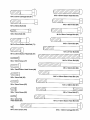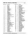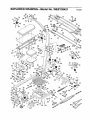
1
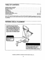
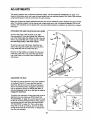
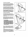
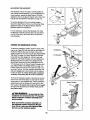
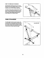
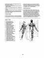
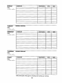
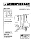
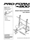
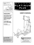
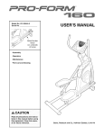
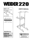
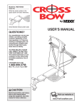
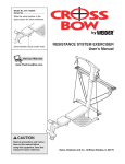
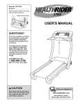
Model No. WESY59421
Serial No.
Write the serial number in the
space above for future reference.
CR SS
Serial Number Decal (under seat)
QUESTIONS?
USER'S MANUAL
As a manufacturer, we are commitred to providing complete
customer satisfaction. If you
have questions, or if there are
missing or damaged parts, we
will guarantee complete satisfaction through direct assistance from our factory.
TO AVOID DELAYS, PLEASE
CALL DIRECT TO OUR TOLLFREE CUSTOMER
HOT LINE.
The trained technicians on our
customer hot line will provide
immediate assistance, free of
charge.
CUSTOMER HOT LINE:
1-800-999-3756
Mon.-Fri., 6 a.m.-6 p.m. MST
www.TheCrossBow.com
TABLE OF CONTENTS
WARNING DECAL PLACEMENT ..........................................................
IMPORTANT PRECAUTIONS .............................................................
BEFORE YOU BEGIN ...................................................................
ASSEMBLY ...........................................................................
ADJUSTMENTS ......................................................................
CABLE DIAGRAM .....................................................................
EXERCISE GUIDELINES ...............................................................
ORDERING REPLACEMENT PARTS ................................................
LIMITED WARRANTY ...........................................................
2
3
4
5
13
16
17
Back Cover
Back Cover
Note: A PART IDENTIFICATION CHART and a PART LIST/EXPLODED DRAWING are attached in the center of
this manual. Remove the PART IDENTIFICATION CHART and PART LIST/EXPLODED DRAWING before beginning assembly.
WARNING
DECAL PLACEMENT
The decals shown here have been
placed on the resistance system. If a
decal is missing or illegible, please call
our Customer Service Department tollfree at t-800-999-3756, Monday through
Friday, 6 a.m. until 6 p.m. Mountain
Time, to order a free replacement decal.
Apply the decal in the location shown.
hands and
n.gers clear of
IIS area.
• Misuse of thisproductmay resultin seriousinjury.
• Read user's manual andfollow all warnings
and operating instructions prior to use.
Do not allow childrenon or around machine.
removed.
CrossBow by WELDER is a trademark of ICON Health & Fitness, Inc.
2
IMPORTANT
_WARN
PRECAUTIONS
ING:
To .du.
_.
before using the resiStance system.
risk of asdous injury, Bad the following Important precautions
1.
Read ell inatructions In this manuel before
using the resistance system. Uas the resistance system only as described In this manuaL
2.
It is the responsibility of the owner to ensure
that all users of the resistance system are
adequately Informed of ell precoutinno.
3.
The resistam:e system is Intandad for home
use only. Do not use the resistance system In
any commercial, rental, or Inatltuttonel asffing.
4.
Use the resistance system only on s level
surface. Cover the flo_r benasth the resist.
ance systom to protect the floor.
5.
13. When adding resistance, both ends ofthe
crossbows must rest under the two "U'channels. Add and remove crossbows from
the "U"-channels one crossbow at s time.
14, Keep clear of the area around the "U"-channeis while the resistance system is In use.
DO not add or rornove crceshows from the
"U"-channals wNI,e the end of the long cable
is pullad out.
Make sure that ell parts are properly tightaned each time you use the resistance eyetern. Replace any wom parts Immediately.
5.
Keep children under 12 and pets away from
the resistance system at all tim..
7.
Kasp hends and feat away from moving parts.
8.
Always wear athletic shoes for foot protection while exercising.
9.
t2. The resistance system is designed to be
used with _ Included resistance, and the
resistance included with a CrossBow by WElDER" Power Psk. Do not uas the resistance
system with any other type of resistance.
15. Always adjust the crossbow assembly to the
horizontal pos_on and make sure the fulcram knob is serum before using the resistance system,
16. Make sure the rings on the crossbows am
pushed against the crossbow spacer bofom
ualng the resistance system.
17. If you purchase the optional kit bar, always
dlsconuact It frcm the sholt cabias when perform_
an exercise that does not require it.
The kit tower crossbar is not designed to be
used for pug-up exercises. Do not hang on
the cmssber.
18. Make sure the storage knob is In place and
fully tightened each time you use the resistance system.
10. The resistance system is designed to support s maximum user weight of 300 pounds.
19. Make sum that the cables remain on the pulISYI at ell timea. If the cabice bind as you are
exercising, stop immediately and make sure
that the cablas are on the pulleys.
11. Pull on the low pulley cable only while sitting
on the bench or standing on the base plate.
Pull on the high pulley cables only while sitting on the bench, with the seat in one of the
three positions closest to the upright base,
or while standing on the base plate.
20. If you feel pain or dizziness while exercising,
atop Immediately and begin coQling down.
kWARNING:
.._.
beginning this or any exercise program, consult your physician. This
is especially important for persons over the age of 35 or plmmns with pre-existing health problem.
Read all Instrustions before using. ICON assumes no responsibility for personal Injury or property
damage sustained by or through the use of this product.
3
BEFORE YOU BEGIN
Thank you for selectingthe innovativeCrossBow by
WELDER resistancesystem. The resistance system
offers a selectionof stationsdesignedto develop every
major muscle groupof the body. Whether your goal is to
tone your body, builddramaticmuscle size and
strength,or improveyour cardiovascularsystem, the
resistancesystem will help you to achieve the specific
resultsyou want.
after readingthis manual, please call our Customer
Service Department toil-free at 1-800-999-3756,
Monday through Friday,6 a.m. until 6 p.m. Mountain
Time (excludingholidays).To help us assistyou, please
note the productmodel number and serial number
before calling.The model number is WESY59421. The
serial number can be found on a decal attached to the
resistancesystem (see the front cover of this manual).
For your benefit, read this manual carefully before
using the resistance system. If you have questions
Before readingfurther, please review the drawingbelow
and familiadzeyourselfwith the parts that are labeled.
TM
ASSEMBLED
DIMENSIONS:
Height: 82 in.
Width: 64 in.
Depth: 80 in.
Crossbar
Lat Tower
High Pulley
Fulcrum Knob
Crossbows
Upright
Storage Knob
Backrest
Low Pulley
Seat
Base Plate
Leg Level
Seat Knob
4
ASSEMBLY
• Tighten all parts as you assemble them. unless
instructedto do otherwise.
Make Thk'tg= F.al_r for Youmeif
TNsm_ual _s€_ned.to_
thatmerestante_
canhe'assembled
s_
by
• As you assemble the resistance system, make
sure all parts are odented as shown in the drawings
most people, However, it I_,i_=
ntt0 reallz8
that the versatile re,stance system has r_ny
partsandtt_t'theas_
pro=='_ll take
Ume.M_t _op_ _ _at W s6_ngask_pk_ty
of_. assemUy
_ g0_=_t_y.
The included IAIlen wrenche.e.e.e.e.e.e.e.e_
and the following tools (not included) are required for assambly:
Before beginning assembly, carefully read the
following information and instructions:
• Two adjustable
wrenches
• Assembly requires two persons.
• One standard
• Place all parts m a cleared area and remove the
packing materials. Do not d_sposeof the packing
materials until assembly is completed.
• One Phillips screwdriver
• One rubber mallet
screwddver
• Lubricant, such as grease or petroleum jelly,
and soapy water.
• For help identifying small parts, use the PART
IDENTIFICATION CHART. Note: Some small
parts may have been pre-attached for shipping. If
a part is not in the parts bag. check to see if it
has been pre-attached.
Assembly will be more convenient if you have a
socket set, a set of open-end or closed-end
wrenches, or a set of ratchet wrenches.
1
Befo_ l=_=Nng a=._bly, make=am that
you hayedraad =nd nmda_,_tand
_ _
lion In lIND_
Press two 50mm Square Inner Caps (98) into the
Base (1).
3
Attach two Plastic Feet (53) and two Large Plastic
Feet (102) to the Base (1) w=thfour M4 x 16mm
Screws (62).
64
Attach the Upnght (3) to the Base (1) with two
M10 x 66ram Carriage Bolts (83), two M1O x
72mm Bolts (64). and four M10 Nylon Locknuts
(76) as shown. Note: This step will be easier to
complete if the Updght and Base are tipped
on their sides.
76
o_,_,"
_o_---
J 63
5
76
102
L62
2.
Attach a Wheel (31) to the outside of the Base (1)
with an M10 x 108mm Bolt (81), three M10
Washers (75), and an M1O Nylon Locknut(76).
Do not overtighten the Nylon Locknut; the
Wheel must be able to turn easily.
Attach the other Wheel (not shown) in the same
manner.
-TZ.'-]
3.
Press a 38mm x 64mm inner Cap (41) into each
end of the Cross Tube (11).
75
Orient the Cross Tube (11) as shown, with the
welded tubes at the bottom.Attach the Cross
Tube to the Upright (3) with two M10 x 140mm
Carriage Bolts (73), two M10 Washers (75), and
two M10 Nuts (47).
47
Welded
73
11
41
4.
Press a 38mm x 76mm Inner Cap (99) into the
top of the Front Leg (6). Press the Front Leg Foot
(27) onto the bottom of the Front Leg. Note that
the front of the Front Leg Foot is taller than
the back.
99
5_
9
Press a 38mm x 76mm Inner Cap (99) into the
end of the Bench Rail (5).
Attach the Bench Rail (5), with the hook on the
bottom, to the Front Leg (6) with two M10 x
53mm Carriage Bolts (61) and two M10 Nylon
Locknuts (76).
--6
Fron_
5.
Lubricate an M10 x 103mm Bolt (66) with grease.
Attach the Bench Rail (5) to the Upright (3) with
the Bolt and an M10 Nylon Looknut(76). Do not
overtlghten the Locknut; the Bench Rail must
be able to pivot easily.
--27
3O
Insert the bolt
through this hole
76
Tighten the Storage Knob (30) into the Upright (3)
and the Bench Rail (5).
Lubricate
6
6.
Attach the Lat Tower (4) to the Upright (3) with
four M10 x 25mm Button Head Bolts (87), and
four M19 Lock Washers (103).
Attach the Name Plate (89) to the Lat Tower (4)
with t_o M4 x 16mm Screws (62).
62 _.
°°
:
103
-3
7.
Press a 38mm Round Inner Cap (38) into each
end of the Lat Tower Crossbar (10).
70
65
Attach two Eyebolts (34) to the Lat Tower
Crossbar (10) with two M8 Washers (59) and two
M8 Nylon Locknuts (65). Do not overtighten the
Loeknuts; the Eyebolts must be able to rotate
freely.
10
65
Attach the Lat Tower Crossbar (10) to the Lat
Tower (4) with two M10 x 65mm Button Head
Bolts(70), two M10 Washers (75), and the
Crossbar Cover (93). Be sure that the Eyebolts
(34) are oriented as shown in the inset drewing. If they are not, turn the Lat Tower
Crossbar around and reattach it.
8.
75
59
Side View
Attach the Leg Lever Bumper (55) to the Front
Leg (6) with an M4 x 19mm Screw (77).
8
Lubricate
Press two 45mm Square Inner Caps (42) into the
Leg Lever (7).
Lubricate an M10 x 68mm Bolt (56) with grease.
Orient the Leg Lever (7) with the slot on the side
shown. Attach the Leg Lever to the Front Leg (6)
with the Bolt and an M10 Nylon Locknut (76). Do
not overtighten the Nylon Locknut; the Leg
Lever must be able to pivot easily.
76
42
7
g.
Attach two 8mm Metal Spacers (97), a 60mm
Metal Spacer (39), and two Bearing Wheels (46)
to one end of the Seat Carriage (12) with an M8 x
104mm Bolt (60) and an M8 Nylon Locknut (65)
as shown. Be sure the parts are oriented as
shown in the inset drawing; the Seat Knob
(not shown) will not engage the Bench Rail
(not shown) if they are incorrectly oriented.
Do not overtighten the Locknut; the Bearing
Wheels must be able to roll easily.
9
12
6L
_Attach
_-._
•
97 -"_€'_
second
./_.
_
,//
set of wheels
here
i ,L_'-65
_.
Attach two Bearing Wheels (not shown) to the
other end of the Seat Carriage (12) in the
same manner.
/_1
10. Attach the Seat Knob (45) to the Seat Carriage
(12) with two M6 x 13mm Bolts (92) and two M6
Nylon Locknuts (69). Be sure that the slot in the
Knob is aligned with the slot in the Seat
Carriage, as shown.
46
10
Orient the Seat (13), the Seat Backing (9), and
the Seat Carriage (12) as shown. Attach the Seat
and the Seat Backing to the Seat Carriage with
four M6 x 16mm Bolts (82).
Slots
11. Pull out the Seat Knob (45) as far as itwill go, and
set the Seat Carriage (12) on the Bench Rail (5).
11 19
13
///
Loosely attach two 8mm Metal Spacers (97), a
60mm Metal Spacer (39), and two Bearing
Wheels (46) to the center holes in the Seat
Carriage (12) with two M8 Flange Nuts (19) and
the M8 x 114mm Bolt (57). Make sure that the
serrated edge of the Flange Nuts are against
the Seat Carriage.
While a second person presses down on the Seat
(13), hold the wheel assembly firmly against the
bottomof the Bench Rail (5) and propedy tighten
the M8 Flange Nuts (19). Make sure that three
threads are extending past the Nut, and that
the wide sides of all six Wheels (46) are
pressed against the Bench Rail.
ustmentHole
97
_/(_
Engage the Seat Knob (45) into an adjustment
hole in the Bench Rail (5).
8
._6
97
i2. Press two 25mm Square Inner Caps (54) into the
indicated end of the Backrest Frame (15).
12
Attach a Plastic Foot (53) to the Backrest Frame
(15) with an M4 x 16ram Screw (62).
SS
Attach the two Guard Plates (17) to the inside of
the Backrest Frame (15) with four M4 x 16mm
Screws (62).
. 53
L=-li :joo
17_/_
L' 62
L"
17
13. Odent the Backrest (14) and the Backrest
Backing (8) as shown. Attach the Backrest and
the Backrest Backing to the Backrest Frame (15)
with four M6 x 45mm Bolts (58).
13
14
14. Insert the rod on the Backrest Frame (15) into the
slot in the Seat Carriage (12). Hold the Backrest
Frame vertically over the Seat Carriage and
slide the rod into the slot, as shown in the
inset drawing.
14
_%
15. Attach the two 10-Pound Short Crossbow Caps
(20) to the 10-Pound Center Crossbow (44) with
two M4 x 12mm Flat Head Screws (85).
Roa
:
15
96
Attach the two 10-Pound Crossbow Caps (101) to
the 10-Pound Removable Crossbow (67), the two
20-Pound Crossbow Caps (88) to the 20-Pound
Removable Crossbow (36), the four 80-Pound
Crossbow Caps (100) to the two 80-Pound
Crossbows (95), and the two 40-Pound Crossbow
Caps (79) to the 40-Pound Crossbow (96) with
ten M4 x 12mm Flat Head Screws (85).
100
9
16. Locate the Crossbow Fulcrum (18) on the Lat
Tower (4) (see the inset drawing). Slide the
Crossbow Spacer (35) onto the rods on the
Crossbow Fulcrum. Make sure the Spacer is
oriented as shown in the drawing.
16
86
up
Set the Crossbows intothe CrossbowSpacer (35)
in the followingorder: the 1O-PoundRemovable
Crossbow(67), the 20-Pound Removable
Crossbow(36), an 80-Pound Crossbow(95), the
10-Pound Center Crossbow(44), an 8O-Pound
Crossbow(95), and the 40-Pound Crossbow(96).
Make sure the indicated rings are on the side
shown end the arrows point toward the Spacer.
96
Rings on
95
Rods 67
Attach the Crossbow Cover Plate (72), with the
edges up, to the Crossbow Spacer (35) with two
M8 x 19mm Button Head Screws (86).
17
17. Locate the Long Cable (80). Insert one end of
the Cable through the welded tube on the indicated end of the Cross Tube (11) and then through a
Swivel Arm (22). If necessary, use the tip of a
screwdriverto pull the end of the Cable out of the
Swivel Arm. Be sure the Cable Is on the indicated side of the welded rod In the Swivel Arm.
10,
0
71
28--_q
Insert the Swivel Arm (22) into the welded tube
on the Cross Tube (11). Secure the Swivel Arm
with an M4 x 5ram Screw (104).
76
Wrap the Long Cable (80) around a 90mm Pulley
(28). Attach the Pulley inside of the Swivel Arm
(22) with an MIO x 42ram Button Head Bolt (71)
and an M1O Nylon Locknut (76).
18
Flat
Edge
2._,/76
18. Wrap the Long Cable (80) around a 90mm Pulley
(28). Attach the Pulley and a Pulley Guard (29) to
the indicated M1O x 140mm Carriage Bolt (73)
with an M10 Nylon Locknut (76). Be sure the fiat
edge of the Pulley Guard is on the side
shown.
19. Attach a Pulley Housing (94) to the indicated"U"channel on the 10-Pound Center Crossbow (44)
with an M10 x 102mm Button Head Bolt (24), two
Pivot Bushings (74), and an M10 Nylon Locknut
(76).
Wrap the Long Cable (80) around a 90mm Pulley
(28). Attach the Pulley inside of the Pulley
Housing (94) with an M10 x 42mm Button Head
Bolt (71) and an M10 Nylon Locknut (76).
19_.
10
Channel
20. Wrap the Long Cable (80) under a 90mm Pulley
(28) as shown. Attach the Pulley and a Pulley
Guard (29) to the Upright (3) with an M10 x
113mm Button Head Bolt (40) and an M10 Nylon
Locknut (76). Be sure the fiat edge of the
Pulley Guard is on the bottom.
2O
80
Flat
Edge
21. Attach a Pulley Housing (94) to the indicated "U'channel on the lO-Pound Center Crossbow (44)
with an M10 x 102mm Button Head Bolt (24), two
Pivot Bushings(74), and an M10 Nylon Locknut
(76).
21
Wrap the Long Cable (80) around a 90mm Pulley
(28). Attach the Pulley inside of the Pulley
Housing (94) with an M10 x 42mm Button Head
Bolt (71) and an M10 Nylon Locknut (76).
71
28
22. Wrap the Long Cable (80) around a 90mm Pulley
(28). Attach the Pulley and a Pulley Guard (29) to
the indicated M10 x 140mm Carriage Bolt (73)
with an M10 Nylon Locknut(76). Be sure the fiat
edge of the Pulley Guard is on the side
shown.
22
28
80
Edge
23. Make sure there are no Crossbows (not shown)
under the "U"-channels on the 10-Pound Center
Crossbow (not shown). Have a second person
pull on the Long Cable (80) to create slack in the
Cable.
23
Insert the end of the Long Cable (80) through the
welded tube on the indicatedend of the Cross
Tube (11) and then through the remaining Swivel
Arm (22). Be sure the Cable is on the indicated
side of the welded rod in the Swivel Arm.
71
22
80..
Insert the Swivel Arm (22) into the welded tube
on the Cross Tube (11). Secure the Swivel Arm
with an M4 x 5mm Screw (104).
28
Wrap the Long Cable (80) around a 90mm Pulley
(28). Attach the Pulley inside of the Swivel Arm
(22) with an M10 x 42mm Button Head Bolt (71)
and an M10 Nylon Locknut (76).
11
76
24.Locatethe LegLeverCable(32),whichhastwo
endsthatarethesamelengthanda thirdend
thatislonger.
24
RoutethelongestendoftheLegLeverCable
(32)throughtheholeintheFrontLeg(6),and
attachit insideoftheholeintheLegLever(7)
withanM10x 6Omm
Bolt(63)and an M10 Nylon
Locknut (76).
25. Attach a 90mm Pulley (28) inside of the hole in
the Front Leg (6) with an M10 x 91ram Bolt (90),
two 26mm Spacers (52), two M10 Washers (75),
end an MI0 Nylon Locknut (76). Be sure the
Pulley is above the Leg Lever Cable (32).
25
6
9O
Slide the two free ends of the Leg Lever Cable
(32) onto the hook welded to the bottomof the
Bench Rail (5).
Hook
-75
76
26. Locate the two Short Cables (33). Wrap one of
the Cables around a 90mm Pulley (28). Attach
the Pulleyto a High Pulley Housing (21) with an
M10 x 42mm Button Head Boit (71) and an M10
Nylon Locknut (76).
26
76
21
71
Repeat this step with the other Short Cable
(33).
27. Slide the four Foam Pads (26) onto the tubes on
the Front Leg (6) and the Leg Lever (7). Press
four 19ram Round inner Caps (78) into the ends
of the tubes.
27
26
26
7
26
28. Make sure that all parts have been propedy tightened. The use of the remaining parts will be explained in
ADJUSTMENTS, beginning on the followingpage,
Before using the resistance system, pull the long cable a few times to be sure that it moves smoothlyover
the pulleys. If the cable does not move smoothly,find and correct the problem. IMPORTANT: If the cables
are not properly installed, they may be damaged when heavy resistance is used. See the CABLE
DIAGRAM on page t6 for proper cable routing.
12
ADJUSTMENTS
This section explains how to adjust the resistance system. See the EXERCISE GUIDELINES on page 17 for
importantinformationabout how to get the most benefit from your exercise program. Also, refer to the accompanying exercise guide to see the correct form for each exercise.
Make sure all parts are propedy tightened each time you use the resistancesystem. Replace worn parts immediately. The resistancesystem can be cleaned with a damp clothand a mild, non-abrasive detergent. Do not use
solvents. The crossbowscan be cleaned with a vinyland rubber protectant,available at an automotiveor department store.
ATTACHING THE HIGH PULLEYS AND LEG LEVER
To use a high pulley,slide the hook on the High
Pulley Housing (21) onto the Eyebolt (34). Attach the
end of the Short Cable (33) without the ball to the end
of the Long Cable (80)with a Cable Clip (51). Attach
the other high pulley in the same manner.
To use the Leg Lever (not shown), attach the two
ends of the Leg Lever Cable (32) to the ends of the
Long Cable (80) with two Cable Clips (51).
Remove the high pulleys, and detach the Leg Lever
Cable (32), when not in use. Store the ends of the
Leg Lever Cable on the hook under the Bench Rail
(not shown).
Hook
ADJUSTING THE SEAT
The Seat (13) can be secured in any of four positions
on the Bench Rail (5). To move the Seat, pull the
Seat Knob (45) out as far as it will go, and slide the
Seat to the desired position.Engage the Seat Knob
into an adjustment hole in the Bench Rail. Note: It
may be necessary to lift up on the Seat in order to
engage the Seat Knob,
45
To perform row exercises, the leg press strap must be
attached to the long cable (see ATTACHING THE
ACCESSORIES, on page 14), and the Seat (13) must
be able to roll along the Bench Rail (5). First, remove
the backrest from the seat frame (see ADJUSTING
THE BACKREST on page 15). Then, pull the Seat
Knob (45) out as far as it will go, and tum the Knob
so that the pin rests at the end of the "L"-shapedslot
(see the inset drawing).
5
12
Pin
13
45
A'I-fACHING
THE ACCESSORIES
33
\
To attach a Short Handle (49) to a high pulley,flint
attach the htgh pulley to the resistancesystem (see
ATTACHING THE HIGH PULLEYS AND LEG LEVER
on page 13). Then, attach the Short Handle to the
Short Cable (33) with a Cable Clip (51).
4c
The Long Handles (not shown) and the Ankle Strap
(not shown) can be attached to the Long Cable (80)
wtthCable Clips (51). Attach the Leg Press Strap (not
shown) to bothends of the Long Cable, or the optional
lat bar to the Short Cables (33), w_thtwo Cable Clips.
Note: A tat bar is an optional accessory for the
CrossBow by WELDER". To purchase a lat bar,call
our Customer Service Department toll-freeat 1-800999-3756 and ask for model number WEMC04420.
ADJUSTING THE RESISTANCE
To add resistance, hold a "U"-channel on the 10Pound Center Crossbow (44) firmly and push the end
of a crossbow under tt Repeat with the other end of
the crossbow. If more resistance is needed, add one
crossbow at a ttme.
Note. When adding resistance, always start with the
heaviest crossbow to be used, and fintshwtth the
lightest crossbow.When removmg crossbowsfrom
the "U"-channels,start with the lightestcrossbow and
finish with the heaviest.
Crossbows
AWARNING:
ance, make sure Uta( both ends of the crossbow rest under the two "U"-channele. The
rings on the Removable Crossbows (36, 67)must be pushed against the Crossbow Spacer
(3b').Do not add or remove crossbows from
the "U"-channele while the end of the Long
Cable (80) Is pulled out.
Note: The CrossBow by WELDER" uses progresstve
reststance. As the crossbowsbegin to bend, the
amount of reststance will increase gradually.As the
crossbows bend further, the reststancewill mcrease
rapidly
Additional resistance can be added to the CrossBow
by WELDER" raststance system by callingthe
Customer Service number on the back cover of this
manual and askmg for model number WEMC06420
(100-Pound Power Pak) or WEMC09420 (200-Pound
Power Pak)
14
ADJUSTING THE BACKREST
The Backrest (14) can be used in a level positionor
one of three inclined positions. To use the Backrest in
a level position,secure the Seat Frame (12) to the
adjustment hole in the Bench Rail (5) next to the Front
Leg (6) (see ADJUSTING THE SEAT on page 13).
To use the Backrest (14) in an inclined position,
secure the Seat Frame (12) to one of the other three
adjustment holes in the Bench Rail (5). Rest the
Backrest against the Upright (3).
For row exercises, remove the Backrest (14). Hold
the Backrest vertically over the Seat (13) and lift the
rod out of the slot in the Seat Frame (12) (see the
mset drawing).
STORING THE RESISTANCE SYSTEM
To store the resistance system, slide the ends of the
Leg Lever Cable (32) onto the hook on the bottomof
the Bench Rail (5). Be sure the Seat (13) is in the
positionclosest to the Front Leg (6) (see ADJUSTING
THE SEAT on page 13) Next, remove the Storage
Knob (30) from the Upnght (3). Lift the Front Leg
toward the Lat Tower Crossbar (10), and tighten the
Storage Knob into the side of the Upright and the
Bench Rail. Remove all of the crossbowsfrom the
"U"-channels on the 10-Pound Center Crossbow (44)
(see ADJUSTING THE RESISTANCE on page 14).
Finally, loosen the Fulcrum Knob (43) and pull it out
as far as it will go. Turn the crossbow assembly vertio
cally and engage the Fulcrum Knob into the fulcrum
on the Lat Tower (4). Note: Storing the crossbows
vertically will prolong the life of the crossbows.
Crossbows,
"U"-Channel
To move the resistance system, place the toe of your
shoe on the end of the Base (1) and hold the resistance system in the indicated area. "131t
the resistance
system back onto the Wheels (31) and roll it to the
new location Be careful not to let the Front Leg (6)
or Leg Lever (7) pinch your hands when you tilt
the system back.
WARNING:
Stored Position
se=n tl.t =nof
Hold in
this area
croubows areremoved fromthe "U"_mnels
beforemovingthe crossbowauembly to the
stored posWo..
Make sure that the crosslsow asund_
me hodz=_ pos_
is In
endthatU_ Sto_
Knob (30) is In I_ace and fully t_hfened each
time you use the resistance system.
15
USING THE REMOVABLE CROSSBOWS
The Removable Crossbows (36, 67) can be used to
exercise apart from the resistancesystem, as shown in
the video or on the exemise guide. To remove a
Crossbow,pull it out of the CrossbowSpacer (35).
67 36
To replace the Removable Crossbows (36, 67), slide
them into the Crossbow Spacer (35) from the side
shown, so that the arrows on the rings point toward
the Crossbow Spacer. Make sure the rings are
pushed against the Crossbow Spacer.
CABLE DIAGRAM
The cable diagram shows the proper routingof the
Long Cable (80). Use the diagram to make sure that
the cable has been assembled correctly.If the cable
has not been correctly routed, the resistance system
will not function properly and damage may occur. The
numbers show the correct route for the cable.
Long Cable (80)
16
EXERCISE
GUIDELINES
THE FOUR BASIC TYPES OF WORKOUTS
PERSONALIZING YOUR EXERCISE PROGRAM
Muscle Building
To increase the size and strength of your muscles,
push them close to their maximum capacity.Your muscles will continuallyadapt and grow as you progressively increase the intensityof your exercise. You can
adjust the intensity level of an individualexercise in
two ways:
• by changing the amount of resistance used
• by changing the number of repetitions or sets performed. (A =repetition" is one complete cycle of an
exercise, such as one sit-up. A "set"is a series of
repetitions.)
Determiningthe exact length of time for each workout,
as well as the number of repetitionsor sets completed,
is an individualmatter. It is importantto avoid overdoing it dudng the first few months of your exercise program. You shouldprogress at your own pace and be
sensitiveto your body's signals. If you experience pain
or dizziness at any time while exercising, stop immediately and begin cooling down. Find out what is wrong
before continuing.Remember that adequate rest and a
properdiet are importantfactors in any exercise program.
WARMING UP
The proper amount of resistance for each exercise
depends upon the individualuser. You must gauge
your limits and select the amount of resistancethat is
right for you. Begin with 3 sets of 8 repetitionsfor each
exercise you perform. Rest for 3 minutes after each
set. When you can complete 3 sets of 12 repetitions
without difficulty,increase the amount of resistance.
Begin each workout with 5 to 10 minutesof stretching
and light exercise to warm up. Warming up prepares
your body for more strenuous exercise by increasing
circulation,raisingyour body temperature and delivering more oxygen to your muscles.
WORKING OUT
Toning
You can tone your muscles by pushing them to a moderete percentage of their capacity. Select a moderate
amount of resistanceand increase the number of repetitions in each set. Complete as many sets of 15 to
20 repetitionsas possiblewithout discomfort.Rest for
1 minute after each set. Work your muscles by completing more sets rather than by using high amounts of
resistance.
Each workout should include6 to 10 different exercises. Select exercises for every major muscle group,
emphasizing areas that you want to develop most. To
give balance and vadety to your workouts,vary the
exercises from session to session.
Schedule your workouts for the time of day when your
energy level is the highest. Each workout should be
followed by at least one day of rest. Once you find the
schedule that is right for you, stick with it.
Weight Loss
To lose weight, use a low amount of resistance and
increase the number of repetitions in each set.
Exercise for 20 to 30 minutes, resting for a maximum
of 30 seconds between sets.
EXERCISE FORM
Cross Training
Cross training is an efficientway to get a complete and
well-balanced fitness program.An example of a balanced program is:
• Plan strength training workouts on Monday,
Wednesday, and Friday.
• Plan 20 to 30 minutes of aerobic exercise, such as
runningon a treadmill or riding on an ellipticalor
exercise bike, on Tuesday and Thursday.
• Rest from both strength training and aerobic exercise
for at least one full day each week to give your body
time to regenerate.
The combination of strength training and aerobic exercise will reshape and strengthenyour body, plus develop your heart and lungs.
17
Maintaining proper form is an essential part of an
effective exercise program. This requires moving
throughthe full range of motion for each exercise, and
moving only the appropriate parts of the body.
Exercising in an uncontrolledmanner will leave you
feeling exhausted. On the exercise guide accompanying this manual you will find photographsshowing the
correct form for several exercises, and a list of the
muscles affected. Refer to the muscle chart on page
18 to find the names of the muscles.
The repetitions in each set should be performed
smoothly and without pausing. The exertion stage of
each repetitionshould last about half as long as the
return stage. Proper breathing is important. Exhale
during the exertion stage of each repetitionand inhale
during the return stroke. Never hold your breath.
Rest for a short period of time after each set. The
ideal resting periods are:
• Rest for three minutes after each set for a muscle
building workout.
• Rest for one minute after each set for a toning workout.
• Rest for 30 seconds after each set for a weight less
workout.
Plan to spend the first couple of weeks familiarizing
yourself with the equipment and learning the proper
form for each exercise.
slowly as you stretch and do not bounce. Ease into
each stretch gradually and go only as far as you can
without strain. Stretchingat the end of each workout
is an effective way to increase flexibility.
STAYING MOTIVATED
For motivation,keep a record of each workout.The
chart on page 19 of this manual can be photocopied
and used to schedule and recordyour workouts. List
the date, the exercises performed, the resistance
used, and the numbers of sets and repetitionscompleted. Record your weight and key body measurements at the end of every month. Remember, the key
to achievingthe greatest resultsis to make exercise a
regular and enjoyable part of your everyday life•
COOLING DOWN
End each workout with 5 to 10 minutes of stretching.
Include stretches for both your arms and legs. Move
MUSCLE CHART
A.
B.
C.
D.
E.
F.
G•
H.
L
J.
K.
L.
M.
N.
O.
P.
Q.
R.
S.
T.
U.
V.
W.
Stemomastoid(neck)
PectorelisMajor (chest)
Biceps(frontof arm)
Obliques(waist)
Brachioradials(forearm)
Hip Flexors (upper thigh)
Abductor(outerthigh)
Quaddceps (frontof thigh)
Sartodus (front of thigh)
Tibialis Anterior (front of calf)
Soleus (front of calf)
Rectus Abdominus (stomach)
Adductor (inner thigh)
Trapezius (upper back)
Rhomboideus (upper back)
Deltoid (shoulder)
Triceps (back of arm)
Latissimus Dorsi (mid back)
Spinae Erectors (lower back)
Gluteus Medius (hip)
Gluteus Maximus (buttocks)
Hamstring (back of leg)
Gastrocnemius (back of calf)
R
S
V
18
MONDAY
EXERCISE
RESISTANCE
SETS
REPS
RESISTANCE
SETS
REPS
RESISTANCE
SETS
REPS
Date:
/
/
AEROBIC EXERCISE
TUESDAY
Date:
I
/
WEDNESDAY
EXERCISE
Da_:
/
/
THURSDAY
AEROBIC EXERCISE
Date:
I
I
FRIDAY
EXERCISE
Date:
/
/
Make photocopiesof this page for schedulingand recordingyour workouts.
19
ORDERING
REPLACEMENT
PARTS
To order replacement pads, simply cell our Customer Service Department toll-free at 1-800-999-3756, Monday
through Fdday, 6 a.m. until 6 p.m. Mountain Time (excluding holidays). To help us assistyou, please be prepared to give the followinginformation:
• The MODEL NUMBER of the product (WESY59421)
• The NAME of the product (CrossBow by WELDER" resistance system)
• The SERIAL NUMBER of the product (see the front cover of this manual)
• The KEY NUMBER and DESCRIPTION of the part(s) (see the PART LIST and EXPLODED DRAWING in the
center of this manual)
LIMITED WARRANTY
ICON Health & Fitness, Inc. (ICON), warrants this product to be free from defects in workmanship and
material, under normal use and service conditions.ICON warrants the resistance crossbowsfor the lifetime of the product, the seats and vinyl for a pedod of five (5) years from the date of purchase, and all
other parts for five (5) years. This warranty extends onlyto the odginal purchaser. ICON's obligationunder
this warranty is limited to replacing or repairing, at ICON's option, the productthrough one of its authorized service centers.All repairs for whichwarranty claims are made must be pre-authodzed by ICON. This
warranty does not extend to any productor damage to a productcaused by or attdbutableto freight damage, abuse, misuse, improper or abnormal usage or repairs not provided by an ICON authodzed service
center; products used for commemial or rental purposes; or products used as store display models. No
other warranty beyond that specificallyset forth above is authorized by ICON.
ICON is not responsible or liable for indirect, special or consequentialdamages arising out of or in connection with the use or performance of the productor damages with respect to any economic loss, loss
of property, loss of revenues or profits,loss of enjoyment or use, costs of removal or installationor other
consequentialdamages of whatsoever nature. Some states do not allow the exclusionor limitationof incidental or consequentialdamages. Accordingly, the above limitationmay not apply to you.
The warranty extended hereunder is in lieu of any and all other warranties and any implied warranties of
merchantabilityor fitness for a particular purpose is limited in itsscope and duration to the terms set forth
herein. Some states do not allow limitationson how long an impliedwarranty lasts.Accordingly,the above
limitationmay not apply to you.
This warrantygives you specificlegal dghts. You may also have other rightswhich vary from state to state.
ICON HEALTH & FITNESS, INC., 1500 S. 1000 W., LOGAN, UT 84321-9813
Part No. 192239 R1202B
Pdnted in China © 2002 ICON Health & Fitness, Inc.
PART IDENTIFICATION
CHART
Refer to the drawings below to identify small parts used in assembly.The number in parentheses below each
drawing is the key number of the part, from the PART LIST on the reverse side of this page. Note: Some small
parts may have been pre-attached. If a part is not in the parts bag, check to see if it has been pre-attached.
@@
M6 Nylon Locknut (69)
M8 Flange Nut (19)
MI0 Nut (47)
M10 Lock Washer (103)
©8
19ram Round Inner Cap (78)
M8 Nylon Locknut (65)
25mm Square Inner Cap (54)
M10 Nylon Locknut (76)
M8 Washer (59)
M10 Washer (75)
38mm Round Inner Cap (38)
45mm Square Inner Cap (42)
38mm x 64ram Inner Cap (41)
50mm Square Inner Cap (98)
38mm x 76turn Inner Cap (99)
_\\\\\\\1
-_
M10 x 65mm Button Head Bolt (70)
M10 x 53ram Carraige Bolt (61)
_\\\\\\\1
M10 x 68ram Bolt (56)
M10 x 6Omm Bolt (63)
_\\\\\\\1
_\\\\\\
M10 X 66mm Carriage Bolt (83)
M8 x 45ram Bolt (58)
_\\\\\\\l
M10 x 72ram Bolt (64)
M10 x 42ram Button Head Bolt (71)
_\\\\\\\1
M10 x 91mm Bolt (90)
M10 x 25ram Button Head Bolt (87)
_\\\\\\\\\\\\\\\\\\\
,_
M10 x 103ram Bolt (66)
M4 x 19mm Screw (77)
&\\\\\\\\\\\\\\\\ I
M8 x 104mm Bolt (60)
M8 x 19ram Button Head Screw (86)
M10 x 102mm Button Head Bolt (24)
M6 x 16ram Bolt (82)
_\\\\\\\_
M10 x 108mm Bolt (81)
M4 x 16ram Screw (62)
[_\\\\\_1
M6 x 13mm Screw (92)
M4 x 12mm Flat
Head Screw (85)
M4 x 5ram Screw (104)
k\\\\\\l
M8 x114mm
Bolt (57)
M10 x 113mm Button Head Bolt (40)
M10 x 140ram Carriage Bolt (73)
PART LISTmModel
Key No.
Qty.
1
2
3
4
5
6
7
8
9
10
11
12
13
14
15
16
17
18
19
20
21
22
23
24
25
26
27
28
29
30
31
32
33
34
35
36
37
38
39
40
41
42
43
44
45
46
47
48
49
50
51
52
53
54
55
1
1
1
1
1
1
1
1
1
1
1
1
1
1
1
1
2
1
2
2
2
2
2
2
4
4
1
10
3
1
2
1
2
2
1
1
2
2
3
1
2
2
1
1
1
6
2
1
2
1
4
2
3
2
1
No. WESY59421
Description
Base
Base Plate
Upright
Lat Tower
Bench Rail
Front Leg
Leg Lever
Backrest Backing
Seat Backing
Lat Tower Crossbar
Cross Tube
Seat Carriage
Seat
Backrest
Backrest Frame
Backrest Cap
Guard Plate
Crossbow Fulcrum
M8 Flange Nut
10-Pound Short Crossbow Cap
High Pulley Housing
Swivel Arm
Grip Tape
M10 x 102mm Button Head Bolt
Arm Bushing
Foam Pad
Front Leg Foot
90mm Pulley
Pulley Guard
Storage Knob
Wheel
Leg Lever Cable
Short Cable
Eyebolt
Crossbow Spacer
20-Pound Removable Crossbow
Fulcrum Bushing
38mm Round Inner Cap
60ram Metal Spacer
M10 x 113mm Button Head Bolt
38mm x 64mm Inner Cap
45mm Square Inner Cap
Fulcrum Knob
10-Pound Center Crossbow
Seat Knob
Bearing Wheel
M10 Nut
Leg Press Strap
Short Handle
Ankle Strap
Cable Clip
26mm Spacer
Plastic Foot
25mm Square Inner Cap
Leg Lever Bumper
R1202B
Key No.
Qty.
56
57
58
59
60
61
62
63
64
65
66
67
68
69
70
71
72
73
74
75
76
77
78
79
80
81
82
83
84
85
86
87
88
89
90
91
92
93
94
95
96
97
98
99
100
101
102
103
104
#
#
#
#
#
1
1
4
2
2
2
15
1
2
4
1
1
2
2
2
6
1
2
4
12
23
1
4
2
1
2
4
2
1
12
2
4
2
1
1
1
2
1
2
2
1
6
2
2
4
2
2
4
2
1
1
1
2
1
Description
M10 x 68mm Bolt
M8 x 114mm Bolt
M6 x 45mm Bolt
M8 Washer
M8 x 104mm Bolt
M10 x 53mm Carriage Bolt
M4 x 16mm Screw
M10 x 60mm Bolt
M10 x 72mm Bolt
M8 Nylon Locknut
M10 x 103mm Bolt
10-Pound Removable Crossbow
Long Handle
M6 Nylon Locknut
M10 x 65mm Button Head Bolt
M10 x 42mm Button Head Bolt
CrossbowCover Plate
M10 x 140mm Carriage Bolt
Pivot Bushing
M10 Washer
M10 Nylon Locknut
M4 x 19mm Screw
19mm Round Inner Cap
40-Pound Crossbow Cap
Long Cable
M10 x 108mm Bolt
M6 x 16mm Bolt
M10 x 66mm Carriage Bolt
Fulcrum Endcap
M4 x 12mm Flat Head Screw
M8 x 19mm Button Head Screw
M10 x 25mm Button Head Bolt
20-Pound Crossbow Cap
Name Plate
M10 x 91mm Bolt
Retainer Ring
M6 x 13mm Bolt
Crossbar Cover
Pulley Housing
80-Pound Crossbow
40-Pound Crossbow
8mm Metal Spacer
50mm Square Inner Cap
38mm x 76mm Inner Cap
80-Pound Crossbow Cap
10-Pound Crossbow Cap
Large Plastic Foot
M10 LockWasher
M4 x 5mm Screw
User's Manual
Exemise Guide
Exercise Decal
Allen Wrench
Allen Wrench
Note: "/f' indicates a non-illustratedpart. Specificationsare subjectto change without notice. See the back cover
of the user's manual for informationabout ordering replacement pads.
EXPLODED
DRAWINGmModel
No. WESY59421
R1202B
86
96
79
44
36
21
101
8
67
62
15
,,
62
_.-_8
.-"
87
.--'"
11
87
9
28
28
:
17
°
76
°
_
i
57
6O
82
40
82
104
80
76
64
41
71
25
22
98
75
76
56_
78
,
'
62
62
102"_
83
51
81
48