1
Series 988
User’s Manual
Includes 986, 987, 988 and 989
1/8 DIN Microprocessor-Based Temperature/Process Controller
User Levels:
• New User........................... go to Introduction
• Experienced User................... go to page 4.1
Installers:
• Set-up..................................... go to page 1.1
• Wiring & Installation................ go to page 2.1
96
TOTAL
3 Year Warranty
ISO 9001
Registered Company
Winona, Minnesota USA
Watlow Controls
1241 Bundy Blvd., P.O. Box 5580, Winona, Minnesota USA 55987-5580
Phone: (507) 454-5300, Fax: (507) 452-4507 http://www.watlow.com
0600-0009-0001 Rev W
March 1999
Supersedes: 0600-0009-0001 Rev V
$10.00
Made in the U.S.A.
Printed on Recycled Paper 10% Postconsumer Waste
a.TOC.wc 5/14/1999 8:57 AM Page 1
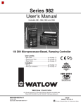
Table of Contents
Introduction to the Watlow Series 988
Controllers
ii
Using this Manual
ii
Document Every Step
iii
Notes, Cautions and Warnings
iii
Technical Assistance
iii
We Value Your Feedback
Chapter 1
Hardware Setup
1.1 Dip Switch Locations and Functions
Chapter 2
Installation and Wiring
2.1 Panel Cutout and Dimensions
2.2 Installing the Series 988
2.4 Wiring the Series 988
2.4 Input-to-output Isolation
2.4 Power Wiring
2.5 Sensor Installation Guidelines
2.6 Wiring Example
2.8 Input 1 Wiring
2.9 Input 2 Wiring
2.11 Event Input 1 Wiring
2.12 Output 1 Wiring
2.13 Output 2 Wiring
2.14 Output 3 Wiring
2.15 Output 4 Wiring
Chapter 3
Front Panel and Display Loop
3.1 Keys and Displays
3.2 Display Loop
Chapter 4
The Setup Menus
4.1 Navigating the Setup Menus
4.2 Input Menu
4.18 Output Menu
4.34 Global Menu
4.44 Communications Menu
Chapter 6
The Factory Menus
6.1 Navigating the Factory Menus
6.2 Panel Lockout Menu
6.7 Diagnostics Menu
6.13 Calibration Menu
Chapter 7
Tuning, Manual Operation,
Alarms and Error Codes
7.1 Auto-tuning (Heat and/or Cool)
7.2 Manual Tuning
7.4 Manual and Automatic Operation
7.5 Changing the Output 3 Alarm Jumper
7.6 Using Alarms
7.8 Error Code E1 and E2 Messages
7.9 Error Code Actions
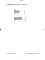
Chapter 8
General Software
8.2 Burst Fire
8.4 Communications
8.6 Dead Band
8.8 Digital Events
8.10 Heater Current
8.12 Input Filter
8.14 Input Linearization
8.16 Ramp to Set Point
8.18 Remote Set Point
8.20 Retransmit
8.22 Slidewire Feedback
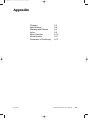
Appendix
A.2 Glossary
A.4 Specifications
A.5 Warranty and Returns
A.6 Index
A.10 Menu Overview
A.11 Model Number – Ordering Information
A.12 Declaration of Conformity
Chapter 5
The Operation Menus
5.1 Navigating the Operation Menus
5.2 System Menu
5.9 PID A and PID B Menus
Table of Contents
WATLOW Series 988 User’s Manual
C0-intro.wc 5/14/1999 8:57 AM Page i
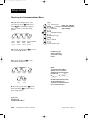
Introduction to the
Watlow Series 988 Controllers
Figure Int.1 The Series 988
Controllers.
Watlow’s Series 988 controllers set a new standard in the controller industry by packing an impressive array of features into an 1/8-DIN package.
No other controller offers the flexibility, compact size and durability of the
Series 988. It can control a wide variety of temperature and process applications, with a broad range of input and output options that allow control
of virtually any process variable.
The Series 988 is the only 1/8 DIN controller that can provide single-unit
cascade control of a process. Its other features include heater current
monitoring, remote set point input, ratio control and valve control through
slidewire feedback. The Series 988 also delivers expanded auto-tuning
capabilities, increased alarm functionality and several unique control algorithms.
When we refer to the “Series 988” controller, we refer also to the horizontal
and low-voltage versions of the Series 988: the 986, 987, 988 and 989. We
recommend that you read all of this manual’s introduction to familiarize
yourself with the conventions and content of this manual and the steps to
setting up a Series 988 controller. Make sure you understand the
“Caution” and “Warning” symbols we use in the book.
Introduction
WATLOW Series 988 User’s Manual
i
C0-intro.wc 5/14/1999 8:57 AM Page ii
Introduction
Using this Manual
This manual provides the information you will need to install and operate
a Series 988 controller.
If you need information about Series 988 configurations and model numbers, refer to the Appendix of this manual or, for more detailed information, to Optimizing Your Process System with the Series 988 Controller: An
Application Guide for the Watlow Series 988 Family.
If your Series 988 controller will be used for data communications, you
will also need our communications manual, Data Communications with the
Watlow Series 988 Family of Controllers (green cover).
˜
NOTE:
The 12-digit number
is printed on the top
of the stickers on
each side of the
controller’s case
and on the righthand or top circuit
board.
˜
NOTE:
The Menu Overview
in the Appendix
shows all the
menus and
prompts.
Series 988 controllers are calibrated in the factory, but if you need to do
periodic calibration you will need our calibration manual, Calibrating
Watlow Process Controllers, (blue cover).
This manual explains the five steps of setting up a Series 988 controller:
1.
2.
3.
4.
5.
Set and document all of the DIP switches, if applicable: Chapter 1.
Mount the controller: Chapter 2.
Wire and document the controller wiring: Chapter 2.
Configure and document the controller software: Chapters 3-6.
Run, test and adjust your application. Update documentation.
Chapters 7 and 8 and the Appendix provide detailed advice, definitions
and specifications along with application examples to help you optimize
the safety and performance of your application. Use the Table of Contents
and Index to find specific information.
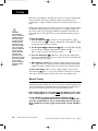
Document Every Step
The Series 988 provides powerful and complex features. Carefully document each step of the setup and any subsequent changes. This will make
it much easier to change, adjust and troubleshoot your application.
Make the configuration documentation available to engineers and technicians, on all shifts, who may need to work with the Series 988. We provide
space in this manual to record configurations. You may prefer to photocopy the blank forms and keep them in a separate binder. However you
maintain your documentation, be sure to replace all old copies of the documentation with updated versions whenever the controller configuration is
changed.
ii
WATLOW Series 988 User’s Manual
Introduction
C0-intro.wc 5/14/1999 8:57 AM Page iii
Introduction
Notes, Cautions and Warnings
We use note, caution and warning symbols throughout this book to draw
your attention to important operational and safety information.
A bold text “NOTE” marks a short message in the margin to alert you to
an important detail.
A bold text “CAUTION” safety alert appears with information that is
important for protecting your equipment and performance. Be especially
careful to read and follow all cautions that apply to your application.
A bold text “WARNING” safety alert appears with information that is
important for protecting you, others and equipment from damage. Pay
very close attention to all warnings that apply to your application.
The ç symbol (an exclamation point in a triangle) precedes a general
CAUTION or WARNING statement.
The Ó symbol (a lightning bolt in a triangle) precedes an electric shock
hazard CAUTION or WARNING safety statement.
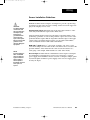
Technical Assistance
If you encounter a problem with your Watlow controller, review all of your
configuration information for each step of the setup to verify that your
selections are consistent with your applications.
If the problem persists after checking all the steps, you can get technical
assistance by calling Watlow Controls at (507) 454-5300, between 7 a.m.
and 5 p.m. CST, and asking for an applications engineer. When you call
have the following information on hand: the controller’s model number
(the 12-digit number is printed on the top of the stickers on each side of
the controller’s case and on the right-hand or top circuit board); your
user’s manual; all configuration information; and the Diagnostics Menu
readings.
We Value Your Feedback
Your comments and suggestions on this manual are welcome. Please send
them to, Technical Writer, Watlow Controls, 1241 Bundy Blvd., P.O. Box
5580, Winona, MN 55987-5580 or call (507) 454-5300 or fax (507) 4524507. The Series 988 User’s Manual is copyrighted by Watlow Winona,
Inc., © March 1999, with all rights reserved. (1657)
Introduction
WATLOW Series 988 User’s Manual
iii
C1.wc 5/14/1999 8:42 AM Page 1.1
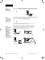
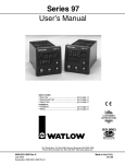
Chapter 1 Hardware Setup
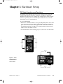
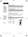
DIP Switch Locations and Functions
The Watlow Series 988 has at least one and as many as six dual in-line
package (DIP) switches inside the controller, depending on the model
number. They allow users to configure the controller for a variety of input
sensors, to provide power for external signal conditioners or to lockout
front panel access to some functions.
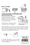
To set any DIP switch:
• Remove the controller from the case by pressing firmly on the two release
tabs on one side or the top of the bezel until they unsnap. Then firmly
press the two release tabs on the opposite side or the bottom of the control until they unsnap. You will need to gently rock the bezel back and
forth to release it from the chassis.
• Use the illustrations on the following pages to locate and set each DIP switch.
WATL W
PROCESS
Release
Tabs
L1
L2
DEV
% OUT
L3
L4
Release
Tabs
DISPLAY
AUTO
MAN
MODE
SERIES 988
Release
Tabs
WATL W
DSPY
Figure 1.1 - Press
the release tabs to
remove the controller chassis.
MODE
PROCESS
L1
L2
L3
DEV
AUTO
% OUT
MAN
L4
SERIES 989
Release
Tabs
Hardware Setup, Chapter 1
WATLOW Series 988 User’s Manual
1.1
C1.wc 5/14/1999 8:42 AM Page 1.2
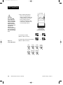
DIP Switches
˜
NOTE:
The Input 2 DIP
switch is mounted
upside down.
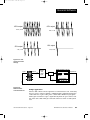
1. Set the input DIP
switches to match the
sensors you are using
in your application.
Only controllers with
model number 98_ _2_ _ _-_ _ _ _ or 98_ __2_ _-_ _ _ _ have an
input DIP switch.
Input 2 DIP
ON
Input 1 DIP
ON
Controller Chassis
Rear View
Input 1
˜
3
2
2
1
1
O
N
↑
3
2
2
1
1
O
N
↑
3
2
3
3
3
WATLOW Series 988 User’s Manual
2
1
0-20 or 4-20mA; 0-5, 1-5 or 0-10V
O
N
↑
1
O
N
↑
Figure 1.2 Input DIP switches.
3
3
thermocouple: J, K, T, N, E, C, D, Pt2
or 0-50mV (high impedance)
O
N
↑
2
2
thermocouple: R, S or B
O
N
↑
1
1
RTD (100 Ω)
O
N
↑
O
N
↑
NOTE:
Only controllers
with the indicated
model numbers
have these DIP
switches.
1.2
Input 2
(98 _ _-2_ _ _-_ _ _ _) (98 _ _-_2_ _-_ _ _ _)
Hardware Setup, Chapter 1
C1.wc 5/14/1999 8:42 AM Page 1.3
DIP Switches
˜
NOTE:
For other voltages
or current settings
contact the factory.
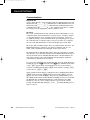
2. Set DIP switches for
outputs equipped with
an external signal conditioner power supply.
Only controllers with
model number 98_ _-_
_ _T-_ _ _ _, 98_ _-_ _ _
_-T_ _ _ or 98_ _-_ _ _
_-_T_ _ have an external signal conditioner
power supply.
O utput 1
Option Board
on
off
O utput 2
Option Board and DIP
O utput 3
Option Board and DIP
off
on
off
on
O utput 4
Option Board and DIP
Controlle r Chassis
Top V ie w (9 8 6 & 9 8 8 )
Le ft-side V ie w (9 8 7 & 9 8 9 )
˜
NOTE:
Only controllers
with the indicated
model numbers
have these DIP
switches.
Output 2
(98 _ _-_ _ _T-_ _ _ _)
20V ± 5% @ 30mA
12V ± 5% @ 30mA
Figure 1.3 External signal conditioner power supply DIPs.
5V ± 5% @ 30mA
O
N
↑
O
N
↑
O
N
↑
1
2
1
2
1
2
Output 3
(98 _ _-_ _ _ _-T_ _ _)
O
N
↑
O
N
↑
O
N
↑
1
2
1
2
1
2
Output 4
(98 _ _-_ _ _ _-_T_ _)
O
N
↑
O
N
↑
O
N
↑
1
2
1
2
1
2
3. When the DIP switches are set, gently insert the controller chassis into
the case and push it firmly into place until all four tabs snap into place.
Hardware Setup, Chapter 1
WATLOW Series 988 User’s Manual
1.3
C1.wc 5/14/1999 8:42 AM Page 1.4
DIP Switches
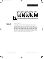
ç
CAUTION:
The lockout DIP
switch makes the
Setup and Factory
menus unavailable.
Configure all the
Setup and Factory
menus before locking them out.
Failure to do so
could result in damage to equipment in
the event of a setup
error.
4. The lockout DIP switch
hides the Setup Menus
(Input, Output, Global and
Communications) and the
Factory Menus (Panel
Lockout, Diagnostics and
Calibration). All units have
a lockout DIP switch.
O
N
↑
no hardware lockout
(Switch 1 has no effect.)
Figure 1.4 Lockout DIP switch.
lockout Setup and Factory menus
(Switch 1 has no effect.)
Input
Output
O
N
↑
1
2
O
N
↑
or
1
2
Global
O
N
↑
or
1
2
1
2
Communications
[InPt] [OtPt] [GLbL] [COM
[`SEt]
Panel
Lockout
[`SEt]
[`SEt]
[`SEt]
Diagnostics Calibration
[PLOC] [diAG] [`CAL]
[Fcty]
1.4
WATLOW Series 988 User’s Manual
[Fcty]
[Fcty]
Hardware Setup, Chapter 1
C2.wc 5/14/1999 8:44 AM Page 2.1
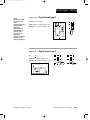
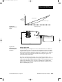
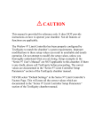
Chapter 2 Installation and Wiring
˜
WATL W
4.03"
(102mm)
NOTE:
Space panel
cutouts at least 1.66
inches (42.2mm)
apart.
PROCESS
WATL W
L1
L2
L3
4.03"
(102mm)
L4
DSPY
2.18"
(55 mm)
PROCESS
DEV
DISPLAY
% OUT
AUTO
MAN
˜
MODE
L1
L2
L3
DEV
AUTO
% OUT
MAN
SERIES 989
L4
MODE
SERIES 988
NOTE:
Adjustable mounting brackets can be
side-mounted.
2.18"
(55 mm)
Adjustable
Mounting Bracket
Panel
˜
Panel Cutout
Maximum Panel
Thickness
0.38" (9.65mm)
NOTE:
Holes can be cut in
the panel using a
Greenlee 1/8 DIN
Hydraulic Kit
#60068 (punch
#60069, die #60070).
3.62" + 0.03 -0.00
(92mm + 0.8)
Figure 2.1 Series 988 and
Series 989
dimensions and
terminal number
layout.
1
4.06"
(103 mm)
0.68"
(17 mm)
1.77 + 0.02 -0.00
(45mm + 0.6)
11
2
21
22
12
3
13
4
14
5
15
6
16
10
1
9
23
17
8
18
7
6
5
4
3
18
17
16
15
14
13
24
19
7
8
2
21
22
12
20
9
23
10
Installation and Wiring, Chapter 2
24
11
19
20
WATLOW Series 988 User’s Manual
2.1
C2.wc 5/14/1999 8:44 AM Page 2.2
Installation
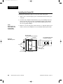
Installing the Series 988
Installing and mounting requires access to the back of the panel.
1. Make a panel cutout using the panel cutout dimensions from the previous page.
2. To remove the controller chassis from its case, press in firmly on the two
tabs on one side or the top of the bezel until they unsnap, then unsnap
the two tabs on the opposite side or the bottom. Pull the chassis out of
the case by gently rocking it.
˜
NOTE:
Removing the controller chassis from
its case makes
mounting easier.
3. Slide the case into the panel cutout. Check to see that the gasket is not
twisted, and is seated within the case bezel flush with the panel. Slide
Side (986 or 988)
or Top and Bottom (987 or 989) View
Panel
Figure 2.2 Side and top view.
Adjustable
Mounting Bracket
Top and Bottom (986 or 988)
or Side (987 or 989) View
Release Tabs
Mounting Slots
Bezel
External Gasket
2.2
WATLOW Series 988 User’s Manual
Mounting Collar
Installation and Wiring, Chapter 2
C2.wc 5/14/1999 8:44 AM Page 2.3
Installation
the mounting collar over the back of the control.
4. Loosen the mounting bracket screws enough to allow for the mounting
collar and panel thickness. Place each mounting bracket into the
mounting slots (head of the screw facing the back of the controller).
Push each bracket backward then down to secure it to the control
case. To guarantee a proper NEMA 4X seal, Series 986 and 988
units (vertical) must have the mounting brackets located on either
side of the unit. When installing Series 987 and 989 units (horizontal) the brackets must be on the top and bottom of the unit.
ç
CAUTION:
Follow the installation procedure
exactly to guarantee
a proper NEMA 4X
seal. Make sure the
gasket between the
panel and the rim of
the case is not
twisted and is seated properly. Failure
to do so could
result in damage to
equipment.
5. Make sure the case is seated properly. Tighten the installation screws
firmly against the mounting collar to secure the unit. To ensure a
NEMA 4X seal, there should be no space between the bezel and
panel. Overtightening the screws will distort the case and make it difficult to remove or replace the controller.
6. Make sure the inside gasket is seated properly and not twisted.
Insert the controller chassis into its case and press the bezel until all
four tabs snap.
7. To release the mounting brackets, loosen the mounting bracket screws
and push the brackets forward, then pull it up and out.
Installation and Wiring, Chapter 2
WATLOW Series 988 User’s Manual
2.3
C2.wc 5/14/1999 8:44 AM Page 2.4
Wiring
Wiring the Series 988
∫
WARNING:
To avoid potential
electric shock, use
National Electric
Code (NEC) safety
practices when
wiring and connecting this unit to a
power source and
to electrical sensors
or peripheral
devices. Failure to
do so could result
in injury or death.
˜
NOTE:
Input-to-output isolation is defeated
when the external
signal conditioner
power supply is
used to power a
transmitter connected to input 1 or
input 2.
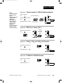
Wiring options depend on the model number and DIP switch settings.
Check the terminal designation stickers on either side of the controller
and compare your model number to those shown here and with the model
number breakdown on the inside back cover of this manual.
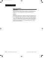
Input-to-output Isolation
The Series 988 uses optical isolation between the analog inputs and the
controller outputs/digital input. This isolation provides a 500VÅ (ac) barrier to prevent ground loops when using grounded sensors and/or peripheral equipment.
Here is a breakdown of the isolation barriers:
• Analog inputs 1 and 2 are grouped together.
• Outputs 1 through 4 and the standard event input are grouped together.
This does not apply to Output 4 when configured as communications.
• The digital communications output (4) is separate from the above
groups.
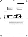
Power Wiring
‡ (ac/dc) nominal, (85 to 264 actual)
100 to 240V‡
Vertical Package
Horizontal Package
98 8 _ - _ _ _ _ - _ _ _ _
98 9 _ - _ _ _ _ - _ _ _ _
L1
+
L2
-
fuse
21
22
11
earth ground
‡ (ac/dc) nominal, (20 to 30 actual)
24 to 28 V‡
Figure 2.4 Power wiring.
2.4
Vertical Package
Horizontal Package
WATLOW Series 988 User’s Manual
98 6 _ - _ _ _ _ - _ _ _ _
98 7 _ - _ _ _ _ - _ _ _ _
Installation and Wiring, Chapter 2
C2.wc 5/14/1999 8:44 AM Page 2.5
Wiring
Sensor Installation Guidelines
ç
CAUTION:
The Series 988 will
not function with
two grounded thermocouple inputs.
Avoid using a
grounded thermocouple for both
input 1 and input 2.
Failure to follow this
guideline could
result in damage to
equipment.
NOTE:
Input-to-output isolation is defeated
when the external
signal conditioner
power supply is
used to power a
transmitter connected to input 1 or
input 2.
Maintain isolation between input 1 and input 2 to prevent a ground loop.
A ground loop may cause incorrect readings, dashes across the upper display or the display of error codes.
Thermocouple input: Extension wire for thermocouples must be of the
same alloy as the thermocouple itself to limit errors.
Using grounded thermocouples for both input 1 and input 2 may create
ground loop problems. To correct this problem, replace at least one of the
grounded thermocouples with an ungrounded thermocouple. If the application requires grounded thermocouples, use an isolated transmitter,
such as a Watlow Gordon 5702 isolated transmitter.
RTD (100 Ω) input: Each 1Ω of lead wire resistance can cause a +2°C
error when using a two-wire RTD. A three-wire RTD sensor overcomes this
problem. All three wires must have the same electrical resistance (i.e.,
same gauge, same length, multi-stranded or solid, same metal).
Process input: Isolation must be maintained between input 1 and input
2. If both input 1 and input 2 are used as process inputs, a separate
power supply and transmitter must be used for each input. Output option
T (external signal conditioner power supply) can be used to supply power
for only one input.
Installation and Wiring, Chapter 2
WATLOW Series 988 User’s Manual
2.5
C2.wc 5/14/1999 8:44 AM Page 2.6
Wiring Example
∫
WARNING:
To avoid potential
electric shock, use
National Electric
Code (NEC) safety
practices when
wiring and connecting this unit to a
power source and
to electrical sensors or peripheral
devices. Failure to
do so could result
in injury or death.
ç
L1
120VÅ (ac)
L2
high-temperature
light
earth ground
21 22 11
1 2 (+)
1
SSR-240-10A-DC1
1 3 (-)
out
1
4
dc input
SSR
2
3
5
92A3-1DJ1-0000
limit control
in
heater
9 (+)
13
1 0 (-)
WARNING:
Install high or low
temperature limit
control protection
in systems where
an over temperature fault condition
could present a fire
hazard or other hazard. Failure to
install temperature
limit control protection where a potential hazard exists
could result in damage to equipment,
property and injury
to personnel.
ç
10
+
red
process sensor
optional
normally open
momentary switch
limit sensor
120VÅ (ac)
L1
1
L2
21
1
14
11
-
988A-10CA-AARR
rear view
22
3
2
4 (+)
2
5
3
(-)
Series 988
988A-10CA-AARR
temperature control
9
10
12
4
WARNING:
To avoid damage to
property and equipment, and/or injury
of loss of life, use
National Electric
Code (NEC) standard wiring practices to install and
operate the Series
988. Failure to do
so could result in
such damage,
and/or injury or
death.
6
11
13
7
(+)
in
3-32VÎ (dc)
(-)
SSR-240-10A-DC1
solid-state relay, dc input
1 CR-1
5
6
7
1
8
1
11
out
24-240VÅ (ac)
9
1
8
12
13
13
9
(+)
14
10
(-)
15
11
11
12
10
Figure 2.6 System wiring
example.
WATLOW Series 988 User’s Manual
17
2
2
Series 92
92A3-1DJ1-0000
limit control
3
16
4
1
heater
2
14
10
13
2.6
high-limit
mechanical
contactor
coil
fuse
1CR
2
5
R
18
high-temperature light
2
Installation and Wiring, Chapter 2
C2.wc 5/14/1999 8:44 AM Page 2.7
Wiring Notes
L1
L2
earth ground
11
21
power
22
ç
WARNING:
To avoid damage to
property and equipment, and/or injury
of loss of life, use
National Electric
Code (NEC) standard wiring practices to install and
operate the Series
988. Failure to do
so could result in
such damage,
and/or injury or
death.
˜
NOTE:
Sketch in your
application on this
page or a copy of it.
See wiring examples in this chapter
and in the Appendix.
Figure 2.7 Wiring notes.
Installation and Wiring, Chapter 2
WATLOW Series 988 User’s Manual
2.7
C2.wc 5/14/1999 8:44 AM Page 2.8
Input 1 Wiring
Figure 2.8a — Thermocouple
˜
NOTE:
Successful installation requires five
steps:
• Model number and
software choice
(Appendix);
• DIP switch settings (Chapter 1);
• Sensor match
(Chapter 2 and
Appendix);
• Sensor installation
(Chapter 2); and
• Wiring (Chapter 2).
or 0-50mV (high impedance)
Thermocouple only
98 _ _ - 1 _ _ _ - _ _ _ _ (no DIP switches)
Universal signal conditioner
98 _ _ - 2 _ _ _ - _ _ _ _
O
N
↑
Input impedance: 20MΩ
1
2
3
O
N
↑
J, K, T, N, C, E, D, Pt2,
0-50mV DIP Settings
1
2
3
+
9
- 10
R, S, B
DIP Settings
+
9
- 10
0-50mV
Figure 2.8b — RTD
(2- or 3-wire) (100 Ω)
Jumper
#9 to #10
for 2-wire
RTD
Universal signal conditioner
98 _ _ - 2 _ _ _ - _ _ _ _
O
N
↑
1
2
3
DIP Switch
Setting
Î,
Figure 2.8c — 0-5VÎ
S1 8
S1
S2 9
S2
9
S3
10
10
8
Î or 0-10VÎ
Î (dc) Process
1-5VÎ
Universal signal conditioner
98 _ _ - 2 _ _ _ - _ _ _ _
Input impedance: 10KΩ
O
N
↑
1
2
3
DIP Switch
Setting
Figure 2.8d — 0-20mA
+ 9
- 10
or 4-20mA Process
Universal signal conditioner
98 _ _ - 2 _ _ _ - _ _ _ _
O
N
↑
Input impedance: 7Ω
2.8
WATLOW Series 988 User’s Manual
1
2
3
DIP Switch
Setting
-
8
+
10
Installation and Wiring, Chapter 2
C2.wc 5/14/1999 8:44 AM Page 2.9
Input 2 Wiring
Figure 2.9a — Thermocouple
or 0-50mV (high impedance)
Thermocouple only
98 _ _ - _ 1 _ _ - _ _ _ _ (no DIP switches)
Universal signal conditioner
O
N
↑
3
1
2
3
R, S, B
DIP Settings
J, K, T, N, C, E, D, Pt2,
0-50mV DIP Settings
19 +
20 0-50mV
19 +
20 -
(2- or 3-wire) (100 Ω)
Jumper
#19 to #20
for 2-wire
RTD
Universal signal conditioner
98 _ _ - _ 2 _ _ - _ _ _ _
O
N
↑
1
2
3
DIP Switch
Setting
Î,
Figure 2.9c — 0-5VÎ
18
S1
18 S1
19
S2
19 S2
20 S3
20
Î or 0-10VÎ
Î (dc) Process
1-5VÎ
Universal signal conditioner
1
2
3
98 _ _ - _ 2 _ _ - _ _ _ _
O
N
↑
Figure 2.9b — RTD
2
Input impedance: 20MΩ
1
98 _ _ - _ 2 _ _ - _ _ _ _
O
N
↑
NOTE:
Successful installation requires five
steps:
• Model number and
software choice
(Appendix);
• DIP switch settings (Chapter 1);
• Sensor match
(Chapter 2 and
Appendix);
• Sensor installation
(Chapter 2); and
• Wiring (Chapter 2).
DIP Switch
Setting
Input impedance: 10KΩ
19
20
or 4-20mA Process
Universal signal conditioner
2
3
Input impedance: 7Ω
1
98 _ _ - _ 2 _ _ - _ _ _ _
DIP Switch
Setting
O
N
↑
Figure 2.9d — 0-20mA
+
-
18 20 +
Installation and Wiring, Chapter 2
WATLOW Series 988 User’s Manual
2.9
C2.wc 5/14/1999 8:44 AM Page 2.10
Input 2 Wiring
NOTE:
See Chapter 8 for
information on
slidewire feedback.
Figure 2.10a — Slidewire
Feedback or Potentiometer Input
98 _ _ - _ 3 _ _ - _ _ _ _
18
CCW
19
Wiper
20
CW
˜
NOTE:
A process output
cannot be installed
on output 1 when
using a current
transformer input.
Figure 2.10b — Current
Transformer Input
98 _ _ - _ 4 _ _ - _ _ _ _
The current transformer must be purchased separately. Watlow current
transformer part number 16-0246 (up to 50 amps).
NOTE:
Successful installation requires five
steps:
• Model number and
software choice
(Appendix);
• DIP switch settings (Chapter 1);
• Sensor match
(Chapter 2 and
Appendix);
• Sensor installation
(Chapter 2); and
• Wiring (Chapter 2).
Systems that use more than 50 Amps need an interstage transformer.
For example, if you use a 300A current transformer, part #16-0073, and
an interstage transformer, part #16-0176, the 300A current transformer
provides a 5A signal to the interstage transformer. In turn, the transformer sends a 20mA maximum signal to the controller.
AC Load
19
A
L2
0 to
20mA
Load wire
CT
19
20
20
L1
Center leg not used
Si l h
Single-phase
Single-phase current sensing up to 300 amps
CT
T1
Wh
Bk
Bk
Bk
T3
T2
3-phase using 2 current transformers
WATLOW Series 988 User’s Manual
Wh
T3
19
20mA
5A
T1
19
20
Red
Bk
Phase
dot
2.10
0 to 5A
AC
20
Red
16-0176
Transformer
CT
T2
3-phase current sensing up to 300 amps.
Installation and Wiring, Chapter 2
C2.wc 5/14/1999 8:44 AM Page 2.11
Event Input 1 Wiring
NOTE:
Successful installation requires five
steps:
• Model number and
software choice
(Appendix);
• DIP switch settings (Chapter 1);
• Sensor match
(Chapter 2 and
Appendix);
• Sensor installation
(Chapter 2); and
• Wiring (Chapter 2).
Figure 2.11a — Digital
Event Input 1
Available on all units.
OPTO
ISOLATOR
open 14-36VÎ (dc) Event Input 1 off
closed 0-3VÎ (dc) Event Input 1 on
4.99KΩ
.01µf
750Ω
+24VÎ (dc)
23
+
10KΩ
24
-
4.99KΩ
Internal Circuitry
23
Figure 2.10c — Digital
24
Event Input 2
98 _ _ - _ 5 _ _ - _ _ _ _
open 0-3VÎ (dc) Event Input 2 off
closed 14-36VÎ (dc) Event Input 2 on
18
19
+5VÎ (VDC)
20
Internal Circuitry
20
+
-
100Ω
4.7KΩ
1KΩ
.01µf
750Ω
18
19
20
Installation and Wiring, Chapter 2
WATLOW Series 988 User’s Manual
2.11
C2.wc 5/14/1999 8:44 AM Page 2.12
Output 1 Wiring
NOTE:
Successful installation requires five
steps:
• Model number and
software choice
(Appendix);
• DIP switch settings (Chapter 1);
• Sensor match
(Chapter 2 and
Appendix);
• Sensor installation
(Chapter 2); and
• Wiring (Chapter 2).
Figure 2.12a — AC
Outputs
Solid-state Relay with Contact Suppression
98 _ _ - _ _ B _ - _ _ _ _
0.5 amps, minimum off-state impedance: 20KΩ
Electromechanical Relay with Contact Suppression
(Suppression between NO and COM contacts only)
12 NO
98 _ _ - _ _ D _ - _ _ _ _
14 NC
External
Load
13 COM
L2
L1
Fuse
(#14 for D & E outputs only)
Form C, 5 amps, minimum off-state impedance: 20KΩ
Electromechanical Relay without Contact Suppression
98 _ _ - _ _ E _ - _ _ _ _
Form C, 5 amps off-state impedance: 31MΩ
Solid-state Relay without Contact Suppression
98 _ _ - _ _ K _ - _ _ _ _
0.5 amps, off-state impedance: 31MΩ
NOTE:
Switching inductive
loads (relay coils,
solenoids, etc.) with
the mechanical
relay or solid state
relay output options
requires using an
R.C. suppressor.
Watlow carries the
R.C. suppressor
Quencharc brand
name, which is a
trademark of ITW
Paktron. Watlow
Part No. 0804-01470000.
Figure 2.12b — Switched
DC, Open Collector
98 _ _ - _ _ C _ - _ _ _ _
19 to 32VÎ (dc)
+
790Ω
Î (dc)
Maximum voltage: 42VÎ
Maximum current: 1A
12
12
+
13
-
14
COM
External
Load
13
14
Internal Circuitry
Figure 2.12c — 0-20mA
and 4-20mA Process
98 _ _ - _ _ F _ - _ _ _ _
12
Maximum load impedance: 800Ω
Î,
Figure 2.12d — 0-5VÎ
14
+
-
Î and 0-10VÎ
Î (dc) Process
1-5VÎ
98 _ _ - _ _ F _ - _ _ _ _
13
Minimum load impedance: 1KΩ
2.12
WATLOW Series 988 User’s Manual
14
+
-
Installation and Wiring, Chapter 2
C2.wc 5/14/1999 8:45 AM Page 2.13
Output 2 Wiring
Figure 2.13a — AC
NOTE:
Successful installation requires five
steps:
• Model number and
software choice
(Appendix);
• DIP switch settings (Chapter 1);
• Sensor match
(Chapter 2 and
Appendix);
• Sensor installation
(Chapter 2); and
• Wiring (Chapter 2).
Outputs
Solid-state Relay with Contact Suppression
98 _ _ - _ _ _ B - _ _ _ _
0.5 amps, minimum off-state impedance: 20KΩ
Electromechanical Relay with Contact Suppression
(Suppression between NO and COM contacts only)
External
Load
15
NO
98 _ _ - _ _ _ D - _ _ _ _
16
COM
Form C, 5 amps, minimum off-state impedance: 20KΩ
17
L2
L1
Fuse
NC
(#17 for D & E outputs only)
Electromechanical Relay without Contact Suppression
98 _ _ - _ _ _ E - _ _ _ _
Form C, 5 amps off-state impedance: 31MΩ
Solid-state Relay without Contact Suppression
98 _ _ - _ _ _ K - _ _ _ _
0.5 amps, off-state impedance: 31MΩ
NOTE:
Switching inductive
loads (relay coils,
solenoids, etc.) with
the mechanical
relay or solid state
relay output options
requires using an
R.C. suppressor.
Watlow carries the
R.C. suppressor
Quencharc brand
name, which is a
trademark of ITW
Paktron. Watlow
Part No. 0804-01470000.
˜
NOTE:
Input-to-output isolation is defeated
when the external
signal conditioner
power supply is
used to power a
transmitter connected to input 1 or
input 2.
Figure 2.13b — Switched
DC, Open Collector
98 _ _ - _ _ _ C - _ _ _ _
19 to 32VÎ (dc)
+
790Ω
16
Î (dc)
Maximum voltage: 42VÎ
Maximum current: 1A
Figure 2.13c — 0-20mA
15
17
Internal Circuitry
15
+
16
-
17
COM
External
Load
and 4-20mA Process
98 _ _ - _ _ _ F - _ _ _ _
15
+
17
-
Maximum load impedance: 800Ω
Î,
Figure 2.13d — 0-5VÎ
Î and 0-10VÎ
Î (dc) Process
1-5VÎ
16
98 _ _ - _ _ _ F - _ _ _ _
+
17
-
Minimum load impedance: 1KΩ
Figure 2.13e — External
Signal Conditioner Power Supply
Loop powered
98 _ _ - _ _ _ T - _ _ _ _
15 +
1
16 -
2
V+ Transmitter
V- 4-20mA out
- +
Input
1 or 2
Installation and Wiring, Chapter 2
WATLOW Series 988 User’s Manual
2.13
C2.wc 5/14/1999 8:45 AM Page 2.14
Output 3 Wiring
NOTE:
Successful installation requires five
steps:
• Model number and
software choice
(Appendix);
• DIP switch settings (Chapter 1);
• Sensor match
(Chapter 2 and
Appendix);
• Sensor installation
(Chapter 2); and
• Wiring (Chapter 2).
Figure 2.14a — AC
Outputs
NOTE:
Switching inductive
loads (relay coils,
solenoids, etc.) with
the mechanical
relay or solid state
relay output options
requires using an
R.C. suppressor.
Watlow carries the
R.C. suppressor
Quencharc brand
name, which is a
trademark of ITW
Paktron. Watlow
Part No. 0804-01470000.
Figure 2.14b — Switched
Solid-state Relay with Contact Suppression
98 _ _ - _ _ _ _ - B _ _ _
L2
2
Fuse
Electromechanical Relay without Contact Suppression
98 _ _ - _ _ _ _ - J _ _ _ _
Form A or B, 5 amps, off-state impedance: 31MΩ
Form A or B
alarm jumper
settings (98______-J___ only)
Form A
Solid-state Relay without Contact Suppression
-
98 _ _ - _ _ _ _ - K _ _ _ _
-
Form B
0.5 amps, off-state impedance: 31MΩ
DC
98 _ _ - _ _ _ _ - C _ _ _
19 to 32VÎ (dc)
1
Minimum load resistance: 500Ω
790Ω
External
Load
+
+
1
-
2
2
Internal Circuitry
Figure 2.14c — Process
Retransmit
0-20mA, 4-20mA, Load impedance: 600Ω max.
1
+
-
98 _ _ - _ _ _ _ - M _ _ _
NOTE:
Input-to-output isolation is defeated
when the external
signal conditioner
power supply is
used to power a
transmitter connected to input 1 or
input 2.
1
COM
L1
0.5 amps, minimum off-state impedance: 20KΩ
NC Form B
or
NO Form A
External
Load
2
Î, 1-5VÎ
Î, 0-10VÎ
Î (VDC), Load impedance: 500Ω min.
0-5VÎ
98 _ _ - _ _ _ _ - N _ _ _
Figure 2.14d — External
Signal Conditioner Power Supply
Loop powered
98 _ _ - _ _ _ _ - T _ _ _
˜
NOTE:
See Chapter 1 for
power supply DIP
switch information.
2.14
WATLOW Series 988 User’s Manual
Transmitter V+
4-20mA out V-
+
-
1
2
+ Input
1 or 2
Installation and Wiring, Chapter 2
C2.wc 5/14/1999 8:45 AM Page 2.15
Output 4 Wiring
NOTE:
Successful installation requires five
steps:
• Model number and
software choice
(Appendix);
• DIP switch settings (Chapter 1);
• Sensor match
(Chapter 2 and
Appendix);
• Sensor installation
(Chapter 2); and
• Wiring (Chapter 2).
Figure 2.15a — AC
Outputs
Solid-state Relay with Contact Suppression
98 _ _ - _ _ _ _ - _ B _ _
0.5 amps, minimum off-state impedance: 20KΩ
Electromechanical Relay with Contact Suppression
(Suppression between NO and COM contacts only)
External
Load NO
L2
L1
98 _ _ - _ _ _ _ - _ D _ _ _
5
COM
6
NC
7
Fuse
Form C, 5 amps, minimum off-state impedance: 20KΩ
(#7 for D & E outputs only)
Electromechanical Relay without Contact Suppression
98 _ _ - _ _ _ _ - _ E _ _ _
Form C, 5 amps, off-state impedance: 31MΩ
Solid-state Relay without Contact Suppression
98 _ _ - _ _ _ _ - _ K _ _ _
0.5 amps, off-state impedance: 31MΩ
NOTE:
Switching inductive
loads (relay coils,
solenoids, etc.) with
the mechanical
relay or solid state
relay output options
requires using an
R.C. suppressor.
Watlow carries the
R.C. suppressor
Quencharc brand
name, which is a
trademark of ITW
Paktron. Watlow
Part No. 0804-01470000.
NOTE:
Input-to-output isolation is defeated
when the external
transmitter power
supply is used to
power a signal conditioner connected
to input 1 or input 2.
Figure 2.15b — Switched
98 _ _ - _ _ _ _ - _ C _ _
DC, Open Collector
19 to 32VÎ (dc)
5
Î (dc)
Maximum voltage: 42VÎ
Maximum current: 1A
790Ω
+
6
External
Load
7
5
+
-
6
COM
7
Internal Circuitry
Figure 2.15c — External
Signal Conditioner Power Supply
98 _ _ - _ _ _ _ - _ T _ _
Loop powered
Transmitter V+
4-20mA out V-
˜
+
-
5
6
+ Input
1 or 2
NOTE:
See Chapter 1 for
power supply DIP
switch information.
Controllers with Output 4 (R, S, or U)
For data communications wiring refer to “Data Communications
with the Watlow Series 988 Family of Controllers” manual. This
manual can be downloaded from Watlow’s website at
www.watlow.com, Product Techical Information - Controls.
Installation and Wiring, Chapter 2
WATLOW Series 988 User’s Manual
2.15
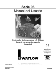
C3.wc 5/14/1999 8:46 AM Page 3.1
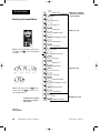
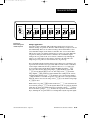
Chapter 3 Front Panel and Display Loop
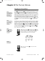
Keys and Displays
Upper Display
Lower Display
Indicates the actual process value,
prompt parameter value or error
code.
Indicates the set point, deviation,
percent power, temperature unit,
menu prompt name or alarm code.
WATL W
DEV LED
These LED’s indicate when output
1, 2, 3 or 4 are active. Outputs can
be configured as:
Ot1
Control
Ot2
Control or Alarm
Ot3
Alarm or Retransmit
Ot4
Alarm or Communications
(flashes on transmit and
receive)
When lit, the lower display shows
the most recent deviation unit from
the set point.
PROCESS
% OUT LED
When lit, the lower display shows
the current percent output.
Up-arrow Key
Increases the value or changes the
parameter in the upper display
(except for set point changes in the
Display Loop, which occur in the
lower display). Hold the key down
to increase the value rapidly. New
data takes effect in five seconds or
when the Mode key or Display key
is pressed.
Down-arrow Key
Decreases the value or changes
the parameter in the upper display
(except for set point changes in the
Display Loop, which occur in the
lower display). Hold the key down
to decrease the value rapidly. New
data takes effect in five seconds or
when the Mode key or Display key
is pressed.
Up + Down Keys
Press simultaneously for three seconds to go to the Setup Menu.
Continue to press both keys for
another three seconds to go to the
Factory Menu. Access to the Setup
and Factory menus can be disabled with lockout DIP switch.
L1
L2
DEV
% OUT
L3
L1, L2, L3, L4
L4
Display Key
DISPLAY
AUTO
MAN
Pressing this key enters the
Display Loop. Press the Display
key at any time to return to this
loop. The next page has more
information on the Display Loop.
MODE
Auto/Man Key
SERIES 988
Mode Key
Enters new data and steps to
the next prompt in the current
menu.
Mode + Up-arrow Keys
Hold the Mode key then press
the Up-arrow key to move
backwards through the current menu. Scrolling stops
when you reach the top of the
menu.
In Manual mode the lower display
shows percent output. Pressed
once, it clears any latched alarm. If
pressed again within five seconds
it will toggle between Auto and
Manual mode.
Auto/Man LED
Lit when the control is in Manual
operation. Press the Auto/Man key
twice to enter Automatic operation.
When blinking, press the Auto/Man
key to toggle between Auto and
Manual. After five seconds without
pressing the Auto/Man key, the
LED stops blinking and returns to
its previous state.
Figure 3.1 Series 988 Keys and Displays
Front Panel and Display Loop, Chapter 3
WATLOW Series 988 User’s Manual
3.1
C3.wc 5/14/1999 8:46 AM Page 3.2
Display Loop
Display Loop
˜
NOTE:
For information on
input 1 [`In1] and
input 2 [`In2]
ranges, refer to
Chapter 4.
The Display Loop is the “home” state of the Series 988 controller. Pressing
the Display key ∂ returns the controller to the Display Loop from any
prompt in any menu. The controller automatically returns to the Display
Loop from any menu when a minute passes without any keys being
pressed.
[`988] current input 1 reading
[`988]
˜
DISPLAY
[`988] current input 2 reading
[Pr`2]
NOTE:
If [``no] is selected
for [`In2], in the
Input Menu, the
[Pr`2] prompt will
not appear.
DISPLAY
DISPLAY
DISPLAY
[`988]
deviation from set point, process 1 minus set point 1 (DEV light on)
[`988] current input 1 reading
percent output (%OUT light on)
[`988] current input 1 reading
[``°C]
Figure 3.2 The Display Loop
3.2
input 2 process (appears only if controller equipped with input 2 hardware)
[`988] current input 1 reading
[`100]
DISPLAY
set point 1 (change with Up-arrow > or Down-arrow < key)
WATLOW Series 988 User’s Manual
units selected (units, °F or °C)
Front Panel and Display Loop, Chapter 3
C4.wc 5/14/1999 8:48 AM Page 4.1
Chapter 4 The Setup Menus
NOTE:
When navigating
through menus,
outputs will be disabled.
˜
NOTE:
Press the Display
key ∂ to return to
the Display Loop
from any point in
any menu.
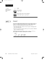
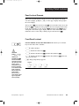
Navigating the Setup Menus
To reach the Setup Menus, begin in the Display Loop and press both the Uparrow > and Down-arrow < keys for three seconds. The Setup Menu
prompt [`SEt] will appear in the lower display, and the Input Menu prompt
[InPt] will appear in the upper display. The four Setup Menus are: Input
[InPt]; Output [OtPt]; Global [GLbL]; and Communications [COM]. Use the
Up-arrow > or Down-arrow < key to select a menu and the Mode key µ
to step through a menu. The Communications Menu appears only on units
equipped with the data communications option.
You will not see every prompt in any of these menus. The unit’s configuration
and model number determine which prompts appear. After stepping through
each menu, the Series 988 returns to the Setup Menu prompt [`SEt]. Use
the Up-arrow > and Down-arrow < keys to select the next menu, or use
the Mode key µ to advance through the same menu again. To move backwards through the menu hold the Mode key µ down and press the Uparrow key >. Use the Up-arrow > or Down-arrow < key to change the
prompt setting.
Refer to the Appendix for model number options. For information about
communications and the communications prompts, refer to the supplemental manual Data Communications with the Watlow Series 988 Family of
Controllers.
WATL W
PROCESS
L1
L2
DEV
L3
L4
DISPLAY
% OUT
AUTO
MAN
❶ Begin in the Display Loop, and press the Up-arrow
> and Down-arrow < keys simultaneously to
reach the Setup Menus.
MODE
SERIES 988
Figure 4.1 Navigating the
Setup Menus.
˜
NOTE:
The lockout DIP
switch hides the
Setup Menus. See
Chapter 1.
[Inpt]
[OtPt]
[gLbL]
[COm]
[`Set]
[`Set]
[`Set]
[`Set]
Input
Menu
p. 4.2
Output
Menu
p. 4.18
Global
Menu
p. 4.34
Communications
Menu
p. 4.44
WATL W
PROCESS
L1
L2
DEV
% OUT
L3
L4
❷ Press the Up-arrow key > to select one of the
Setup Menus.
DISPLAY
AUTO
MAN
MODE
SERIES 988
Setup Menus, Chapter 4
WATLOW Series 988 User’s Manual
4.1
C4.wc 5/14/1999 8:48 AM Page 4.2
[Inpt]
Setup-Input
[`Set]
Setup Prompt
[`In1]
Input 1
[deC1]
*Decimal 1
[`rL1]
Range Low 1
[`rH1]
Range High 1
MODE
Reaching the Input Menu
Enter your settings,
from the controller's
upper display.
MODE
MODE
MODE
Input 1 (p. 4.3)
WATL W
MODE
[CAL1]
Calibration Offset 1
[rtd1]
*RTD Calibration Curve 1
[Ftr1]
Software Filter 1
[Lin1]
*Linearization 1
[`ln2]
*Input 2
[`rSp]
*Remote Set Point
[deC2]
*Decimal 2
[`RL2]
*Range Low 2
[`RH2]
*Range High 2
[LrnL]
*Learn Low
[LrnH]
*Learn High
[CAL2]
*Calibration Offset 2
[rtd2]
*RTD Calibration Curve 2
[Ftr2]
*Software Filter 2
[Lin2]
*Linearization 2
[Hunt]
*Hunt
PROCESS
MODE
L1
L2
DEV
% OUT
L3
L4
DISPLAY
MODE
AUTO
MAN
MODE
MODE
SERIES 988
MODE
❸ Select the Input Menu, then press
the Mode key µ to step through the
prompts.
MODE
MODE
MODE
MODE
MODE
…
…
Input 2 (p. 4.9)
MODE
[```0]
[```1]
[Ftr1]
[Ftr1]
[```2] … [``60]
[Ftr1]
[Ftr1]
MODE
MODE
[``no] [root]
[Lin1]
MODE
[Lin1]
MODE
❹ Press the Up-arrow key > or the
Down-arrow key < to select one of
the prompt values.
MODE
MODE
*Prompts may not appear,
depending on controller
configuration.
MODE
[SHYS]
Slidewire (p. 4.16)
*Slidewire Hysteresis
Figure 4.2 The Input Menu.
4.2
WATLOW Series 988 User’s Manual
Setup Menus, Chapter 4
C4.wc 5/14/1999 8:48 AM Page 4.3
Setup-Input
Input Prompts
˜
NOTE:
Decimal points may
not always be in the
position specified
below depending on
the the settings in
the Decimal 1
[dEC1] and Decimal
2 [dEC2] parameters in the Input
Menu.
[`In1]
When you are in the Setup menus, the Series 988 displays the menu selection ( [InPt], [OtPt], [GLbL] or [COM] ) in the upper display, and [`SEt] in
the lower display.
The Up-arrow > or Down-arrow key < selects another menu. Press the
Mode key µ to display the prompt in the lower display and its value in the
upper display. Use the Up-arrow > or Down-arrow < key to change the
value in the upper display. The new value will not take effect until after a
five-second delay or until you press the Mode key µ.
Input 1
Select sensor type for input 1. This selection must match the sensor type
connected to terminals 8, 9 and 10. See Appendix for more information
about sensors.
ç
CAUTION:
Changing the value
of [`In1] changes
most other prompts
to the factory
default values.
Document all settings before changing sensor type.
Verify the correct
sensor type before
making a change.
Failure to follow
this guideline could
result in damage to
equipment or property. Document all
settings before
changing sensor
type.
• Changing the value of [`In1] changes all other prompts to the factory
default values, except the Communications and Lockout menus, the
[`C_F] prompt in the Global Menu and the [`dFL] prompt in the
Calibration Menu. If you change the value, the default warning [dFLt]
will flash in the upper display.
• Changes do not take effect automatically after five seconds; you must
press the Mode key µ to enter the sensor type change and advance to
the next prompt.
[`In1] This prompt always appears.
If
Default
↓
↓
98_ _-1_ _ _-_ _ _ _
no DIP
J
[```J]
K
[```H]
T
[```t]
N
[```n]
E
[```E]
W5
[```C]
W3
[```d]
Pt2
[`Pt2]
0-50mV
[0-50]
thermocouple
only
[`In1]
[`In1]
[`In1]
[`In1]
[`In1]
[`In1]
[`In1]
[`In1]
[`In1]
J
[```J]
K
[```H]
T
[```t]
N
[```n]
E
[```E]
W5
[```C]
W3
[```d]
Pt2
[`Pt2]
0-50mV
[0-50]
[`In1]
[`In1]
[`In1]
[`In1]
[`In1]
[`In1]
[`In1]
[`In1]
[`In1]
R
[```r]
S
[```S]
B
[```b]
[`In1]
[`In1]
[`In1]
98_ _-2_ _ _-_ _ _ _
Input 1 DIP
O
N
↑
1
2
3
thermocouple
[`In1]
Input 1 continued
on next page.
Input 1 DIP
O
N
↑
1
2
3
thermocouple
Setup Menus, Chapter 4
WATLOW Series 988 User’s Manual
4.3
C4.wc 5/14/1999 8:48 AM Page 4.4
Setup-Input
If
↓
[`In1]
Input 1 continued
from previous
page.
Default
↓
Input 1 DIP
O
N
↑
1
2
3
RTD
RTD(0.1°)
[`rtd]
[`r†d]
[`In1]
[`In1]
RTD
Input 1 DIP
O
N
↑
1
2
3
4-20mA
0-20mA
0-5VÎ
1-5VÎ
[4-20]
[0-20]
[`0-5]
[`1-5]
[0-10]
0-10VÎ (dc)
[`In1]
[`In1]
[`In1]
[`In1]
[`In1]
process
[dEC1]
Decimal 1
Select the decimal point location for process type input 1 data. This
prompt, in conjunction with the Range Low and Range High prompts,
allows you to format and limit units of measure for process 1.
• All prompts with units of measure related to input 1 will display in the
selected decimal format.
• This affects propbands, alarm set points, process set points, calibration
offsets, deadbands and ranges.
[dEC1] This prompt appears only if you have set input 1 [`In1] to a
process input or to a thermocouple input set to 0-50mV.
4.4
Default
↓
[```)]
[``)0]
[`)00]
[)000]
[dEC1]
[DEC1]
[dEC1]
[dEC1]
WATLOW Series 988 User’s Manual
Setup Menus, Chapter 4
C4.wc 5/14/1999 8:48 AM Page 4.5
Setup-Input
[`rL1]
Range Low 1 and Range High 1
[`rH1]
Select the low and high limits for input 1. These prompts limit the
adjustment range for the set points. The default values are the same as
the limits of the sensor you selected by setting the input 1 DIP switch and
selecting a value for Input 1 [`In1].
˜
• Process inputs are scaled by these values. Range high is the value displayed when the maximum process signal is present at the input. Range
low is the value displayed when the minimum process signal is present
at the input.
NOTE:
These values do not
affect the low or the
high set point limit
for process alarms.
Example:
Set [`In1] to [4-20]mA.
Set [`rL1] to [`100].
Set [`rH1] to [`500].
A 4mA input will display [`100].
A 12mA input will display [`300].
A 20mA input will display [`500].
• The low and high values of each sensor type are listed on the specifications page of the Appendix.
• Choose between Fahrenheit and Celsius at the [`C_F] prompt in the
Global Menu.
[`rL1] [`rH1] These prompts always appear.
Default
↓
˜
NOTE:
When high impedance [0-50] is
selected for input 1
the range high for
both [``°C] and
[``°F] can be
extended to
[9999]. The range
low when [``°C] is
selected can be
extended to
[-999].
[`rL1]
[`rH1]
Range Low 1 and
Range High 1
continued on next
page.
Setup Menus, Chapter 4
[```J]
[``in]
Default
↓
Default
↓
Default
↓
[``°F]
[`rL1] [`rH1]
[``°C]
[`rL1] [`rH1]
[``32]…[1500]
[```0]…[`816]
[`rL1]
[`rH1]
[`rL1]
[`rH1]
98_ _-1_ _-_ _ _ or
98_ _-2_ _-_ _ _
(K)
[```H]
[-328]…[2500]
[-200]…[1371]
[```t]
[-328]…[`750]
[-200]…[`399]
[```n]
[``32]…[2372]
[```0]…[1300]
[```E]
[-328]…[1470]
[-200]…[`799]
(W5)
[```C]
[``32]…[4200]
[```0]…[2316]
(W3)
[```d]
[``32]…[4200]
[```0]…[2316]
[`Pt2]
[``32]…[2543]
[```0]…[1395]
high impedance
[0-50]
[-999]…[`999]
[-573]…[`573]
WATLOW Series 988 User’s Manual
4.5
C4.wc 5/14/1999 8:48 AM Page 4.6
Setup-Input
[`rL1]
[`rH1]
Range Low 1 and
Range High 1
continued from
previous page.
˜
NOTE:
These values do not
affect the low or the
high set point limit
for process alarms.
[CAL1]
[``°F]
[`rL1]
[```r]
[``°C]
[`rH1]
[`rL1]
[`rH1]
[``32]…[3200]
[```0]…[1760]
[```S]
[``32]…[3200]
[```0]…[1760]
[```b]
[``32]…[3300]
[```0]…[1816]
[`rtd]
[-328]…[1472]
[-200]…[`800]
[`r†d]
[-9(9]…[99(9]
[-7#3]…[53&7]
98_ _-2_ _-_ _ _
only
[`in1]
[4-20]
[-999]…[9999]
units
[0-20]
[-999]…[9999]
units
[`0-5]
[-999]…[9999]
units
[`1-5]
[-999]…[9999]
units
[0-10]
[-999]…[9999]
units
Calibration Offset 1
Offset the input 1 signal by a positive or negative value. This allows you
to compensate for lead resistance, sensor errors or other factors.
[CAL1] This prompt always appears.
If
↓
[``°F]
Default
↓
[-999] … [```0] … [9999]
[`C_F]
[CAL1]
[CAL1]
[CAL1]
(Global Menu)
[``°F] & [`r†d]
[`C_F]
[`In1]
(Global Menu)
(Input Menu)
[``°C]
[-9(9] … [``)0] … [`9(9]
[CAL1]
[CAL1]
[CAL1]
[-999] … [```0] … [9999]
[`C_F]
[CAL1]
[CAL1]
[CAL1]
(Global Menu)
[``°C] & [`r†d]
[`C_F]
[`In1]
(Global Menu)
(Input Menu)
[-5%5] … [``)0] … [`5%5]
[CAL1]
[CAL1]
[CAL1]
[-999] … [```0] … [`999]
a process input
is selected
4.6
WATLOW Series 988 User’s Manual
[CAL1]
[CAL1]
units
[CAL1]
Setup Menus, Chapter 4
C4.wc 5/14/1999 8:48 AM Page 4.7
Setup-Input
[rtd1]
RTD (100Ω) Calibration Curve 1
Select the calibration curve for the RTD 1 input. The RTD input uses
either the European (DIN, 0.003850Ω/Ω/°C) or the Japanese (JIS,
0.003916Ω/Ω/°C) linearization standard.
[rtd1] This prompt appears only if you have set [`In1] to [`rtd] or
[`r†d].
Default
↓
[`din] … [`JIS]
[rtd1]
[Ftr1]
[rtd1]
Software Filter 1
Select the filter time constant, in seconds, for input 1. This smooths a
rapidly changing input signal for display or control purposes.
• Select a positive value to filter only the display.
• Select a negative value to filter the input signal.
• Set the value to [```0] to disable the filter.
[Ftr1] This prompt always appears.
Default
↓
[`-60] … [```0] … [``60]
[Ftr1]
Setup Menus, Chapter 4
[Ftr1]
[Ftr1]
WATLOW Series 988 User’s Manual
4.7
C4.wc 5/14/1999 8:48 AM Page 4.8
Setup-Input
[Lin1]
Linearization 1
Select square root linearization for input 1.
[Lin1] This prompt appears only if you have set [`In1] to a process input
or to a thermocouple set to [0-50]mV.
˜
NOTE:
See Chapter 8 for
more information
on input linearization.
4.8
Default
↓
[``no]
[root]
[Lin1]
[Lin1]
WATLOW Series 988 User’s Manual
Setup Menus, Chapter 4
C4.wc 5/14/1999 8:48 AM Page 4.9
Setup-Input
[`In2]
CAUTION:
Changing the value
of [`In2] changes
most other prompts
to the factory
default values.
Document all settings before changing sensor type.
Verify the correct
sensor type before
making a change.
Failure to follow
this guideline could
result in damage to
equipment or property. Document all
settings before
changing sensor
type.
Input 2
Select sensor type for input 2. This selection must match the sensor
type connected to terminals 18, 19 and 20. See Appendix for more information about sensors.
• Changing the value of [`In2] changes all other prompts to the factory default values, except the Communications and Lockout menus,
the [`C_F] prompt in the Global Menu and the [`dFL] prompt in the
Calibration Menu. If you change the value, the default warning
[dFLt] will flash in the upper display.
• Changes do not take effect automatically after five seconds; you must
press the Mode key µ to enter the sensor type change and advance to
the next prompt.
[`In2] This prompt and other Input 2 prompts appear only on controllers
equipped with input 2 hardware (not 98_ _-_0_ _-_ _ _ _).
If
↓
Default
↓
98_ _-1_ _ _-_ _ _ _
[``no]
J
[```J]
K
[```H]
T
[```t]
N
[```n]
E
[```E]
W5
[```C]
W3
[```d]
Pt2
[`Pt2]
0-50mV
[0-50]
[``In2]
[`In2]
[`In2]
[`In2]
[`In2]
[`In2]
[`In2]
[`In2]
[`In2]
[`In2]
no DIP
˜
thermocouple
only
NOTE:
98_ _-2_ _ _-_ _ _ _
If [``no] is selected
Input 2 DIP
J
K
T
N
E
W5
W3
Pt2
0-50mV
for [`In2] none of
[``no] [```J] [```H] [```t] [```n] [```E] [```C] [```d] [`Pt2] [0-50]
the other input 2
[`In2]
[`In2]
[`In2]
[`In2]
[`In2]
[`In2]
[`In2]
[`In2]
[`In2]
[`In2]
prompts will
appear.
thermocouple
O
N
↑
1
2
3
[``no]
R
[```r]
S
[```S]
B
[```b]
[`In2]
[`In2]
[`In2]
[`In2]
RTD
RTD (0.1°)
[``no]
[`rtd]
[`r†d]
[`In2]
[`In2]
[`In2]
4-20mA
0-20mA
0-5VÎ
1-5VÎ
[``no]
[4-20]
[0-20]
[`0-5]
[`1-5]
[0-10]
[`In2]
[`In2]
[`In2]
[`In2]
[`In2]
[`In2]
Input 2 DIP
O
N
↑
1
2
3
thermocouple
Input 2 DIP
O
N
↑
1
2
3
RTD
Input 2 DIP
O
N
↑
[`In2]
1
2
3
0-10VÎ (dc)
process
Input 2 continued
on next page.
Setup Menus, Chapter 4
WATLOW Series 988 User’s Manual
4.9
C4.wc 5/14/1999 8:48 AM Page 4.10
Setup-Input
[`In2]
Input 2 continued
from previous
page.
If
Default
↓
↓
98_ _-3_ _ _-_ _ _ _
no DIP
resistance
only
slidewire potentiometer
[``no]
[SLid]
[`POt]
[``In2]
[`In2]
[`In2]
98_ _-4_ _ _-_ _ _ _
no DIP
current
transformer
only
current
[``no]
[SLid]
[``In2]
[`In2]
98_ _-5_ _ _-_ _ _ _
no DIP
digital event
only
[`rSP]
event 2
[``no]
[`Ei2]
[``In2]
[`In2]
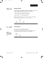
Remote Set Point
Enable a remote set point signal.
[`rSP] This prompt appears only if the controller is equipped with input 2
hardware and if [`In2] is not set to [``no] and if [CntL] (in the Global
Menu) is set to [`nor].
4.10
Default
↓
[`OFF]
[``On]
[`rSP]
[`rSP]
WATLOW Series 988 User’s Manual
Setup Menus, Chapter 4
C4.wc 5/14/1999 8:48 AM Page 4.11
Setup-Input
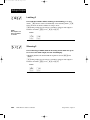
[dEC2]
Decimal 2
Select the decimal point location for process type input 2 data. This
prompt, in conjunction with the Range Low and Range High prompts,
allows you to format and limit units of measure for process 2.
• All prompts with units of measure related to input 2 will display in the
selected decimal format.
• This affects propbands, alarm set points, process set points, calibration
offsets, deadbands and ranges.
[dEC2] This prompt appears only if you have set input 2 [`In2] to a
process input, [Curr] or a thermocouple input set to [0-50] mV.
Default
↓
[```)]
[``)0]
[`)00}
[)000]
[dEC2]
[dEC2]
[dEC2]
[dEC2]
[`rL2]
Range Low 2 and Range High 2
[`rH2]
Select the low and high limits for input 2. These prompts limit the
adjustment range for the set points. The default values are the same as
the limits of the sensor you selected by setting the input 2 DIP switch and
selecting a value for Input 2 [`In2].
• Process inputs are scaled by these values. Range high is the value displayed when the maximum process signal is present at the input. Range
low is the value displayed when the minimum process signal is present
at the input.
Example:
[`rL2]
[`rH2]
Range Low 2 and
Range High 2
continued on next
page.
Setup Menus, Chapter 4
Set [`In2] to [4-20]mA.
Set [`rL2] to [`100].
Set [`rH2] to [`500].
A 4mA input will display [`100].
A 12mA input will display [`300].
A 20mA input will display [`500].
• The low and high values of each sensor type are listed on the specifications page of the Appendix.
• Choose between Fahrenheit and Celsius at the [`C_F] prompt in the
Global Menu.
[`rL2] [`rH2] These prompts appear only if the controller is equipped
with input 2 hardware and with Input 2 [`In2] not set to [``no] or
[`Ei2].
WATLOW Series 988 User’s Manual
4.11
C4.wc 5/14/1999 8:48 AM Page 4.12
Setup-Input
[`rL2]
[`rH2]
Range Low 2 and
Range High 2 continued from previous page.
˜
Default
↓
[```J]
[`in2]
Default
↓
Default
↓
Default
↓
[``°F]
[`rL2] [`rH2]
[``°C]
[`rL2] [`rH2]
[``32]…[1500]
[```0]…[`816]
[`rL2]
[`rH2]
[`rL2]
[`rH2]
98_ _-1_ _-_ _ _ or
98_ _-2_ _-_ _ _
(K)
[```H]
[-328]…[2500]
[-200]…[1371]
[```t]
[-328]…[`750]
[-200]…[`399]
[```n]
[``32]…[2372]
[```0]…[1300]
[```E]
[-328]…[1470]
[-200]…[`799]
[``32]…[4200]
[```0]…[2316]
[```d]
[``32]…[4200]
[```0]…[2316]
[`Pt2]
[``32]…[2543]
[```0]…[1395]
[0-50]
[-999]…[`999]
[-573]…[`573]
[```r]
[``32]…[3200]
[```0]…[1760]
[```S]
[``32]…[3200]
[```0]…[1760]
[```b]
[``32]…[3300]
[```0]…[1816]
[`rtd]
[-328]…[1472]
[-200]…[`800]
[`r†d]
[-9(9]…[99(9]
[-7#3]…[53&7]
(W5)
[```C]
NOTE:
These values do not
affect the low or the
high set point limit
for process alarms.
˜
NOTE:
When high impedance [0-50] is
selected for input 1
the range high for
both [``°C] and
[``°F] can be
extended to [9999].
The range low when
[``°C] is selected
can be extended to
[-999].
(W3)
high impedance
[4-20]
[-999]…[9999]
units
[0-20]
[-999]…[9999]
units
[`0-5]
[-999]…[9999]
units
[`1-5]
[-999]…[9999]
units
[0-10]
[-999]…[9999]
units
[0-50]
[-999]…[9999]
units
[0=00]
[-999]…[9999]
units
[`100]…[1200]
ohms
[```0]…[``50]
amps
[```0]…[1200]
ohms
98_ _-2_ _-_ _ _ only
slidewire
[SLid]
current
[Curr]
potentiometer
[`POt]
4.12
WATLOW Series 988 User’s Manual
Setup Menus, Chapter 4
C4.wc 5/14/1999 8:48 AM Page 4.13
Setup-Input
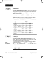
[LrnL]
Learn Low
Write the low-end resistance of the slidewire potentiometer to the
range low 2 parameter.
˜
NOTE:
See Chapter 8 for
more information
on slidewire feedback.
[LrnH]
[LrnL] This prompt appears only on controllers equipped with input 2
hardware and with Input 2 [`In2] set to [SLid] or [`POt].
Default
↓
[``no]
[`YES]
[LrnL]
[LrnL]
Learn High
Write the high-end resistance of the slidewire potentiometer to the
range low 2 parameter.
˜
NOTE:
See Chapter 8 for
more information
on slidewire feedback.
Setup Menus, Chapter 4
[LrnH] This prompt appears only on controllers equipped with input 2
hardware and with Input 2 [`In2] set to [SLid] or [`POt].
Default
↓
[``no]
[`YES]
[LrnH]
[LrnH]
WATLOW Series 988 User’s Manual
4.13
C4.wc 5/14/1999 8:48 AM Page 4.14
Setup-Input
[CAL2]
Calibration Offset 2
Offset the input 2 signal by a positive or negative value. This allows
you to compensate for lead resistance, sensor errors or other factors.
[CAL2] This prompt appears only if the controller is equipped with input 2
hardware and if [`In2] is not set to [``no] or [`Ei2].
If
↓
[``°F]
Minimum
Default Max. setting/range
↓
[-999] … [```0] … [`999]
[`C_F]
[CAL2]
[CAL2]
[CAL2]
(Global Menu)
[``°F] & [`r†d]
[`C_F]
[`In2]
(Global Menu)
(Input Menu)
[``°C]
[-9(9] … [``)0] … [`9(9]
[CAL2]
[CAL2]
[CAL2]
[-555] … [```0] … [`555]
[`C_F]
[CAL2]
[CAL2]
[CAL2]
(Global Menu)
[``°C] & [`r†d]
[`C_F]
[`In2]
(Global Menu)
(Input Menu)
[-5%5] … [``)0] … [`5%5]
[CAL2]
[CAL2]
[CAL2]
[-999] … [```0] … [`999]
[CAL2]
a process input
is selected
[rtd2]
[CAL2]
units
[CAL2]
RTD Calibration Curve 2
Select the calibration curve for the RTD 2 input. The RTD input uses
either the European (DIN, 0.003850Ω/Ω/°C) or Japanese (JIS,
0.003916Ω/Ω/°C) linearization standard.
[rtd2] This prompt appears only on controllers equipped with input 2
hardware and with [`In2] set to [`rtd] or [`r†d].
4.14
Default
↓
[`din]
[`JIS]
[rtd2]
[rtd2]
WATLOW Series 988 User’s Manual
Setup Menus, Chapter 4
C4.wc 5/14/1999 8:48 AM Page 4.15
Setup-Input
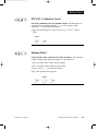
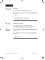
[Ftr2]
Software Filter 2
Select the filter time constant, in seconds, for input 2. This smooths a
rapidly changing input signal for display or control purposes.
• Select a positive value to filter only the display.
• Select a negative value to filter the input signal.
• Set the value to [```0] to disable the filter.
[Ftr2] This prompt appears only on controllers equipped with input 2
hardware and with [`In2] not set to [``no] or [`Ei2].
Default
↓
[`-60] … [```0] … [``60]
[Ftr2]
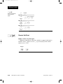
[Lin2]
[Ftr2]
[Ftr2]
Linearization 2
Select square root linearization for input 2.
˜
NOTE:
See Chapter 8 for
more information
on input linearization.
Setup Menus, Chapter 4
[Lin2] This prompt appears only if you have set Input 2 [`In2] to a
process input or to a thermocouple input set to [0-50] mV.
Default
↓
[``no]
[root]
[Lin2]
[Lin2]
WATLOW Series 988 User’s Manual
4.15
C4.wc 5/14/1999 8:48 AM Page 4.16
Setup-Input
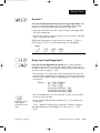
[Hunt]
Hunt
Set the deadband, as a percentage of output, to keep the valve from
hunting.
˜
NOTE:
See Chapter 8 for
more information
on slidewire feedback.
• The slidewire hysteresis [SHYS] setting provides additional control over a
valve.
[Hunt] This prompt appears only if the controller is equipped with slidewire
hardware (98_ _-_3_ _-_ _ _) and with [`In2] set to [SLid].
Default
↓
[``)3] … [``!0] … [10)0]
[Hunt]
4.16
WATLOW Series 988 User’s Manual
[Hunt]
[Hunt]
Setup Menus, Chapter 4
C4.wc 5/14/1999 8:48 AM Page 4.17
Setup-Input
[SHYS]
Slidewire Hysteresis
Set the inner hysteresis, the point at which the valve output turns
off.
˜
NOTE:
See Chapter 8 for
more information
on slidewire feedback.
• The figure below illustrates the interaction between slidewire hysteresis
[SHYS] and hunt [Hunt].
[SHYS] This prompt appears only if the controller is equipped with slidewire
hardware (98_ _-_3_ _-_ _ _ _) and with Input 2 [`In2] set to [SLid]
Default
↓
[```0]
[Hunt]
[SHYS]
[SHYS]
turn-on point (close)
Hunt
Slidewire
Hysteresis
turn-off point (close)
slidewire position
set point
turn-off point (open)
Figure 4.17 Hunt and slidewire
inner hysteresis.
Setup Menus, Chapter 4
turn-on point (open)
WATLOW Series 988 User’s Manual
4.17
C4.wc 5/14/1999 8:48 AM Page 4.18
[OtPt]
Setup-Output
[`set]
Setup Prompt
[`Ot1]
Output 1
[Prc1]
*Process 1
[HyS1}
*Hysteresis 1
[`Ot2]
*Output 2
[Prc2]
*Process 2
Enter your settings,
from the controller's
upper display.
MODE
MODE
Reaching the Output Menu
Output 1 (p. 4.19)
MODE
MODE
❶ Begin in the Display Loop, and
press the Up-arrow > and Downarrow < keys simultaneously for
three seconds to reach the Setup
Menus.
MODE
MODE
[Hys2]x*Hysteresis
2
MODE
Output 2 (p. 4.21)
[Sp2c]
*Set Point 2 Control
[`Al2]
*Alarm 2
[A25d]
*Alarm 2 Side
[LAt2]
*Latching 2
[SIL2]
*Silencing 2
[`Ot3]
*Output 3
[`Al3]
*Alarm 3
[A3sd]
*Alarm 3 Side
[Hys3]
*Hysteresis 3
[Lat3]
*Latching 3
[SIL3]
*Silencing 3
[`Ot4]
*Output 4
[`AL4]
*Alarm 4
[A4Sd}
*Alarm 4 Side
[HyS4]
*Hysteresis 4
[LAt4]
*Latching 4
[SIL4}
*Silencing 4
[Aout]
*Analog Output
[Prc3}
*Process 3
[A`rL]
*Retransmit Low Limit
[A`rH]
*Retransmit High Limit
[ACAL]
*Retransmit Calibration Offset
MODE
[Inpt]
[OtPt]
[gLbL]
[COm]
[`Set]
[`Set]
[`Set]
[`Set]
Input
Menu
p. 4.2
Output
Menu
p. 4.18
Global
Menu
p. 4.34
Communications
Menu
p. 4.44
MODE
MODE
MODE
MODE
❷ Press the Up-arrow key > to select
one of the Setup Menus.
MODE
MODE
MODE
Output 3 (p. 4.25)
MODE
❸ Press the Mode key µ to step
through the prompts.
MODE
MODE
MODE
MODE
[``Ht]
[``CL]
[`Ot1]
[`Ot1]
MODE
…
…
[```1]
[```2]
[Hys2]
[Hys2]
MODE
[```3] … [`999]
[Hys2]
Output 4 (p. 4.28)
MODE
[Hys2]
MODE
❹ Press the Up-arrow key > or the
Down-arrow key < to select one of
the prompt values.
*Prompts may not appear,
depending on controller
configuration.
Figure 4.18 Navigating the
Output Menu.
4.18
WATLOW Series 988 User’s Manual
MODE
MODE
MODE
Output 3 retransmit
(p. 4.31)
MODE
MODE
Setup Menus, Chapter 4
C4.wc 5/14/1999 8:48 AM Page 4.19
Setup-Output
˜
NOTE:
Decimal points may
not always be in the
position specified
below depending
on the the settings
in the Decimal 1
[deC1] and Decimal
2 [deC2] parameters in the Input
Menu.
[`Ot1]
Output Prompts
When you are in the Setup menus, the Series 988 displays the menu
selection ( [InPt], [OtPt], [GLbL] or [COM] ) in the upper display, and
[`SEt] in the lower display.
The Up-arrow > or Down-arrow key < selects another menu. Press the
Mode key µ to display the first prompt in the lower display and its value
in the upper display. Use the Up-arrow > and Down-arrow < keys to
change the value in the upper display. The new value will not take effect
until after a five-second delay or until you press the Mode key µ.
Output 1
Set the way that output 1 will respond to a difference between the set
point and an input variable.
• [``Ht] select reverse action, so that output 1 responds when the input
signal is less than the setpoint.
• [``CL] select direct action, so that output 1 responds when the input
signal is more than the setpoint.
[`Ot1] This prompt always appears.
Setup Menus, Chapter 4
Default
↓
[``Ht]
[``CL]
[`Ot1]
[`Ot1]
WATLOW Series 988 User’s Manual
4.19
C4.wc 5/14/1999 8:48 AM Page 4.20
Setup-Output
[Prc1]
Process 1
Select the process range for output 1.
[Prc1] This prompt appears only on controllers equipped with output 1
process hardware (98_ _-_ _F_-_ _ _ _).
Default
↓
[HYS1]
4-20mA
0-20mA
0-5VÎ
1-5VÎ
0-10VÎ (dc)
[4-20]
[0-20]
[`0-5]
[`1-5]
[0-10]
[Prc1]
[Prc1]
[Prc1]
[Prc1]
[Prc1]
Hysteresis 1
Select the switching hysteresis for output 1. This determines the
change in temperature or process units needed to turn the output from
full on to full off.
[HYS1] This prompt does not appear on controllers equipped with output 1
process hardware (98_ _-_ _F_-_ _ _ _). This prompt only appears with the
controller set up as an on/off controller ( [PBIA] = [```0] ).
If
↓
Default
↓
[``°F]
[```1] … [```3] … [`999]
[`C_F]
[HYS1
][HYS1]
[HYS1]
(Global Menu)
[``°F]
&
[`C_F]
(Global Menu)
[`r†d]
[`In1]
(Input Menu)
[``°C]
[`C_F]
(Global Menu)
[HYS1]
[HYS1]
[HYS1]
[```1] … [```2] … [`555]
[`C_F]
(Global Menu)
[``°C]
[``)1] … [``#0] … [`9(9]
[HYS1]
&
[`r†d]
[`In1]
(Input Menu)
[HYS1]
[HYS1]
[``)1] … [``@0] … [`5%5]
[HYS1]
[HYS1]
[HYS1]
[```1] … [```3] … [`999]
a
4.20
process input
is selected
WATLOW Series 988 User’s Manual
[HYS1]
[HYS1]
units
[HYS1]
Setup Menus, Chapter 4
C4.wc 5/14/1999 8:48 AM Page 4.21
Setup-Output
[`Ot2]
Output 2
Set the way that output 2 will respond to a difference between the set
point and an input variable.
• [`AL2] de-energizes output 2 in an alarm condition.
• [AL2n] energizes output 2 in an alarm condition.
• [``Ht] select reverse action, so that output 2 responds when the input
signal is less than the set point.
• [``CL] select direct action, so that output 2 responds when the input
signal is more than the set point.
[`Ot2] This prompt appears only on controllers equipped with output 2
hardware (not 98_ _-_ _ _A-_ _ _ _). [`AL2] and [AL2n] do not appear if output 2 is a process output (98_ _-_ _ _F-_ _ _ _). [``Ht] and [``CL] do not
appear if [AL90] (in the Global Menu) is set to [dUPL].
[Prc2]
Default
↓
[``no]
[`AL2]
[Al2n]
[``Ht]
[``CL]
[`Ot2]
[`Ot2]
[`Ot2]
[`Ot2]
[`Ot2]
Process 2
Select the process range for output 2.
[Prc2] This prompt appears only on controllers equipped with output 2
process hardware (98_ _-_ _ _F-_ _ _ _) and with [`Ot2] not set to [``no].
Default
↓
Setup Menus, Chapter 4
4-20mA
0-20mA
0-5VÎ
1-5VÎ
[4-20]
[0-20]
[`0-5]
[`1-5]
[0-10]
0-10VÎ (dc)
[Prc2]
[Prc2]
[Prc2]
[Prc2]
[Prc2]
WATLOW Series 988 User’s Manual
4.21
C4.wc 5/14/1999 8:48 AM Page 4.22
Setup-Output
[HYS2]
Hysteresis 2
Select the switching hysteresis for output 2. This determines the
change in temperature or process units needed to turn the output from off
to on.
• If [`AL2] is set to [rAtE] settings for [HYS2] will be in degrees per
minute or units per minute.
• If the input referenced by [`AL2] is set to [`r†d] the range is affected as
listed below.
[HYS2] This prompt appears only on controllers equipped with output 2
hardware and with the controller set up as an on/off controller ([Pb2A} =
[```0]), and with [`Ot2] not set to [``no]. This prompt does not appear
on controllers equipped with output 2 process hardware, ([`In2} = [sLid],
or if [ALg0} in the Global menu = [dUPL]).
If
Default
↓
↓
[``°F]
[```1] … [```3] … [`999]
[`C_F]
(Global Menu)
[``°F]
[`C_F]
(Global Menu)
[HYS2]
&
[`r†d]
[`C_F]
(Global Menu)
[HYS2]
[HYS2]
[```1] … [```2] … [`555]
[`C_F]
(Global Menu)
[``°C]
[HYS2]
[``)1] … [``#0] … [`9(9]
[HYS2]
Input 1 or 2
(see note above)
[``°C]
[HYS2]
[HYS2][
&
[`r†d]
HYS2]
[HYS2]
[``)1] … [``@0] … [`5%5]
[HYS2]
Input 1 or 2
(see note above)
[HYS2]
[HYS2]
[```1] … [```3] … [`999] units
[HYS2]
a process input
is selected
[SP2c]
[HYS2]
[HYS2]
Set Point 2 Control
Select a second set point.
• [``Pr] enables a set point independent from the Set Point 1 [`SP1]
value.
• [``dE] enables a set point at a deviation from the Set Point 1 [`SP1]
value.
[Prc1] This prompt appears only if output 2 hardware is present and is
equal to the output 1 setting.
4.22
Default
↓
[``Pr]
[``dE]
[SPc2]
[SPc2]
WATLOW Series 988 User’s Manual
Setup Menus, Chapter 4
C4.wc 5/14/1999 8:48 AM Page 4.23
Setup-Output
[`AL2]
Alarm 2
Select the alarm type for alarm 2. Select the trigger points for the alarm
with the [A2LO] and [A2HI] settings in the System Menu [`SYS].
• [`Pr1] uses the process signal from input 1. Changing the set point
does not change the alarm response.
˜
NOTE:
See Chapter 7 for
more information
on alarms.
• [`dE1] uses a deviation from the input 1 signal. Changing the set point
changes the alarm response.
• [`Pr2] uses the process signal from input 2. This choice does not appear
if the controller is not equipped with input 2 hardware or if [`In2] is set
to [``no] or [`Ei2].
• [`dE2] uses a deviation from the input 2 signal. This prompt does not
appear if the controller is not equipped with input 2 hardware or if
[`In2] is set to [``no] or [`Ei2].
• [rAtE] uses the rate of change at input 1 in degrees per minute.
[`AL2] This prompt appears only on controllers equipped with output 2
hardware and with [`Ot2] set to [`AL2] or [AL2n].
Default
↓
[`Pr1] [`de1] [`Pr2] [`de2] [rAtE] [``no]
[`AL2]
[A2Sd]
[`AL2]
[`AL2]
[`AL2]
[`AL2]
[`AL2]
Alarm 2 Side
Select what triggers alarm 2.
• [both] triggers an alarm when the signal ≤ [A2LO] or ≥ [A2HI].
• [HigH] triggers an alarm when the signal ≥ [A2HI].
• [LoW] triggers an alarm when the signal ≤ [A2LO].
[A2Sd] This prompt appears only on controllers equipped with output 2
hardware and with [`Ot2] set to [`AL2] or [AL2n].
Default
↓
[both] [HigH] [Low]
[A2Sd]
Setup Menus, Chapter 4
[A2Sd]
[A2Sd]
WATLOW Series 988 User’s Manual
4.23
C4.wc 5/14/1999 8:48 AM Page 4.24
Setup-Output
[LAt2]
Latching 2
Select whether alarm 2 will be latching or non-latching. A latching
alarm [`LAt] must be turned off manually. A non-latching alarm [`nLA]
turns off when an alarm condition no longer exists.
˜
NOTE:
See Chapter 7 for
more information
on alarms.
[SIL2]
[LAt2] This prompt appears only on controllers equipped with output 2
hardware and with [`Ot2] set to [`AL2] or [AL2n].
Default
↓
[`nLA]
[`LAt]
[LAt2]
[LAt2]
Silencing 2
Select silencing to inhibit alarm 2 on startup and to allow the operator to reset the alarm output, not the visual display.
• Silencing disables the alarm until the signal is between [A2LO] and
[A2HI].
[`AL2] This prompt appears only on controllers equipped with output 2
hardware and with [`Ot2] set to [`AL2] or [AL2n].
Default
4.24
↓
[`OFF]
[``On]
[SIL2]
[SIL2]
WATLOW Series 988 User’s Manual
Setup Menus, Chapter 4
C4.wc 5/14/1999 8:48 AM Page 4.25
Setup-Output
[`Ot3]
Output 3
Select the alarm condition for output 3.
• [`AL3] de-energizes output 3 in an alarm condition.
˜
NOTE:
See Chapter 7 for
more information
on alarms.
• [AL3n] energizes output 3 in an alarm condition.
[`Ot3] This prompt appears only on controllers equipped with output 3
hardware for a relay (98_ _-_ _ _ _-B_ _ _, 98_ _-_ _ _ _-J_ _ _ or
98_ _-_ _ _ _-K_ _ _) or switched dc (98_ _-_ _ _ _-C_ _ _).
Default
↓
[`AL3]
[`Ot3]
[`AL3]
[AL3n]
[``no]
[`Ot3]
[`Ot3]
Alarm 3
Select the alarm type for alarm 3.
• [`Pr1] uses the process signal from input 1.
• [`dE1] uses a deviation from the input 1 signal.
• [`Pr2] uses the process signal from input 2. This prompt does not
appear if the controller is not equipped with input 2 hardware or if
[`In2] is set to [``no] or [`Ei2].
• [`dE2] uses a deviation from the input 2 signal. This prompt does not
appear if the controller is not equipped with input 2 hardware or if
[`In2] is set to [``no] or [`Ei2].
• [rAtE] uses the rate of change at input 1 in degrees per minute.
[`AL3] This prompt appears only on controllers equipped with output 3
hardware for a relay (98_ _-_ _ _ _-B_ _ _, 98_ _-_ _ _ _-J_ _ _ or
98_ _-_ _ _ _-K_ _ _) or switched dc (98_ _-_ _ _ _-C_ _ _), and with [`Ot3]
set to [`AL3] or [AL3n].
Default
Setup Menus, Chapter 4
↓
[`Pr1]
[`de1]
[`Pr2]
[`de2]
[rAtE]
[``no]
[`AL3]
[`AL3]
[`AL3]
[`AL3]
[`AL3]
[`AL3]
WATLOW Series 988 User’s Manual
4.25
C4.wc 5/14/1999 8:48 AM Page 4.26
Setup-Output
[A3Sd]
Alarm 3 Side
Select what triggers alarm 3.
˜
• [both] triggers an alarm when the signal ≤ [A3LO] or ≥ [A3HI].
NOTE:
See Chapter 7 for
more information
on alarms.
• [HiGH] triggers an alarm when the signal ≥ [A3HI].
• [LOW] triggers an alarm when the signal ≤ [A3LO].
[A3Sd] This prompt appears only on controllers equipped with output 3
hardware for a relay (98_ _-_ _ _ _-B_ _ _, 98_ _-_ _ _ _-J_ _ _ or
98_ _-_ _ _ _-K_ _ _) or switched dc (98_ _-_ _ _ _-C_ _ _) and with [`Ot3]
set to [`AL3] or [AL3n].
Default
[HYS3]
↓
[both]
[HiGH]
[LOW]
[A3Sd]
[A3Sd]
[A3Sd]
Hysteresis 3
Select the switching hysteresis for alarm 3. This determines the change
in temperature or process units needed to turn the output from off to on.
• If [`AL3] is set to [rAtE] settings for [HYS3] will be in degrees per
minute or units per minute.
• If the input referenced by [`AL3] is set to [`r†d] the range is affected as
listed below.
[HYS3] This prompt appears only on controllers equipped with output 3
hardware for a relay (98_ _-_ _ _ _-B_ _ _, 98_ _-_ _ _ _-J_ _ _ or
98_ _-_ _ _ _-K_ _ _) or switched dc (98_ _-_ _ _ _-C_ _ _).
If
↓
[``°F]
Default
↓
[```1] … [```3] … [`999]
[`C_F]
(Global Menu)
[``°F]
[`C_F]
(Global Menu)
[HYS3]
&
[`r†d]
[`C_F]
(Global Menu)
[HYS3]
[HYS3]
[```1] … [```2] … [`555]
[`C_F]
(Global Menu)
[``°C]
[HYS3]
[``)1] … [``#0] … [`9(9]
[HYS3]
Input 1 or 2
(see note above)
[``°C]
[HYS3]
[HYS3]
&
[`r†d]
[HYS3]
[HYS3]
[``)1] … [``@0] … [`5%5]
[HYS3]
Input 1 or 2
(see note above)
[HYS3]
[HYS3]
[```1] … [```3] … [`999]
a process input
is selected
4.26
WATLOW Series 988 User’s Manual
[HYS3]
[HYS3]
units
[HYS3]
Setup Menus, Chapter 4
C4.wc 5/14/1999 8:48 AM Page 4.27
Setup-Output
[LAt3]
˜
NOTE:
See Chapter 7 for
more information
on alarms.
Latching 3
Select whether alarm 3 will be latching or non-latching. A latching
alarm [`LAt] must be turned off manually. A non-latching alarm [`nLA]
turns off when an alarm condition no longer exists.
[LAt3] This prompt appears only on controllers equipped with output 3
hardware for a relay (98_ _-_ _ _ _-B_ _ _, 98_ _-_ _ _ _-J_ _ _ or
98_ _-_ _ _ _-K_ _ _) or switched dc (98_ _-_ _ _ _-C_ _ _) and with [`Ot3] set
to [`AL3] or [AL3n].
Default
↓
[SIL3]
[`nLA]
[`LAt]
[LAt3]
[LAt3]
Silencing 3
Select silencing to inhibit alarm 3 on startup and to allow the operator to reset the alarm output, not the visual display.
˜
NOTE:
See Chapter 7 for
more information
on alarms.
• Silencing disables the alarm until the signal is between [A3LO] and
[A3HI].
[SIL3] This prompt appears only on controllers equipped with output 3
hardware for a relay (98_ _-_ _ _ _-B_ _ _, 98_ _-_ _ _ _-J_ _ _ or
98_ _-_ _ _ _-K_ _ _) or switched dc (98_ _-_ _ _ _-C_ _ _) and with [`Ot3] set
to [`AL3] or [AL3n].
Default
Setup Menus, Chapter 4
↓
[`OFF]
[``On]
[SIL3]
[SIL3]
WATLOW Series 988 User’s Manual
4.27
C4.wc 5/14/1999 8:48 AM Page 4.28
Setup-Output
[`Ot4]
Output 4
Select the alarm condition for output 4.
˜
• [`AL4] de-energizes output 4 in an alarm condition.
NOTE:
See Chapter 7 for
more information
on alarms.
• [AL4n] energizes output 4 in an alarm condition.
[`Ot4] This prompt appears only on controllers equipped with output 4
hardware for a relay (98_ _-_ _ _ _-_B_ _, 98_ _-_ _ _ _-_D_ _ ,
98_ _-_ _ _ _-_E_ _ or 98_ _-_ _ _ _-_K_ _) or switched dc (98_ _-_ _ _ _-_C_ _).
Default
[`AL4]
↓
[`AL4]
[AL4n]
[`Ot4]
[`Ot4]
Alarm 4
Select the alarm type for alarm 4.
• [`Pr1] uses a process signal from input 1.
• [`dE1] uses a deviation from the input 1 signal.
• [`Pr2] uses the process signal from input 2. This prompt does not
appear if the controller is not equipped with input 2 hardware or if
[`In2] is set to [``no] or [`Ei2].
• [`dE2] uses a deviation from the input 2 signal. This prompt does not
appear if the controller is not equipped with input 2 hardware or if
[`In2] is set to [``no] or [`Ei2].
• [rAtE] uses the rate of change at input 1 in degrees per minute.
[`AL4] This prompt appears only on controllers equipped with output 4
hardware for a relay (98_ _-_ _ _ _-_B_ _, 98_ _-_ _ _ _-_D_ _ ,
98_ _-_ _ _ _-_E_ _ or 98_ _-_ _ _ _-_K_ _) or switched dc (98_ _-_ _ _ _-_C_ _).
Default
4.28
↓
[`Pr1]
[`dE1]
[`Pr2]
[`dE2]
[rAtE]
[``no]
[`AL4]
[`AL4]
[`AL4]
[`AL4]
[`AL4]
[`AL4]
WATLOW Series 988 User’s Manual
Setup Menus, Chapter 4
C4.wc 5/14/1999 8:48 AM Page 4.29
Setup-Output
[A4Sd]
Alarm 4 Side
Select what triggers alarm 4.
• [both] triggers an alarm when the signal ≤ [A4LO] or ≥ [A4HI].
˜
NOTE:
See Chapter 7 for
more information
on alarms.
• [HiGH] triggers an alarm when the signal ≥ [A4HI].
• [LOW] triggers an alarm when the signal ≤ [A4LO].
[A4Sd] This prompt appears only on controllers equipped with output 4
hardware for a relay (98_ _-_ _ _ _-_B_ _, 98_ _-_ _ _ _-_D_ _ ,
98_ _-_ _ _ _-_E_ _ or 98_ _-_ _ _ _-_K_ _) or switched dc (98_ _-_ _ _ _-_C_ _)
and with [`Ot4] set to [`AL4] or [AL4n].
Default
Setup Menus, Chapter 4
↓
[BOTH]
[HIGH]
[LOW]
[A4SD]
[A4SD]
[A4SD]
WATLOW Series 988 User’s Manual
4.29
C4.wc 5/14/1999 8:48 AM Page 4.30
Setup-Output
[HYS4]
Hysteresis 4
Select the switching hysteresis for alarm 4. This determines the change
in temperature or process units needed to turn the output from off to on.
• If [`AL4] is set to [rAtE] settings for [HYS4] will be in degrees per
minute or units per minute.
• If the input referenced by [`AL4] is set to [`r†d] the range is affected as
listed below.
[HYS4] This prompt appears only on controllers equipped with output 4
hardware for a relay (98_ _-_ _ _ _-_B_ _, 98_ _-_ _ _ _-_D_ _ ,
98_ _-_ _ _ _-_E_ _ or 98_ _-_ _ _ _-_K_ _) or switched dc (98_ _-_ _ _ _-_C_ _).
If
↓
[``°F]
Default
↓
[```1] … [```3] … [`999]
[`C_F]
(Global Menu)
[``°F]
[HYS4]
& [`r†d]
[`C_F]
(Global Menu)
[HYS4]
[HYS4]
[```1] … [```2] … [`555]
[`C_F]
(Global Menu)
[``°C]
[HYS4]
[``)1] … [``#0] … [`9(9]
[HYS4]
Input 1 or 2
(see note above)
[``°C]
[HYS4]
[HYS4]
& [`r†d]
[`C_F]
(Global Menu)
[HYS4]
[HYS4]
[``)1] … [``@0] … [`5%5]
[HYS4]
Input 1 or 2
(see note above)
[HYS4]
[HYS4]
[```1] … [```3] … [`999]
[HYS4]
a process input
is selected
[LAt4]
[HYS4]
units
[HYS4]
Latching 4
Select whether alarm 4 will be latching or non-latching. A latching
alarm [`LAT] must be turned off manually. A non-latching alarm [`nLA]
turns off when an alarm condition no longer exists.
˜
NOTE:
See Chapter 7 for
more information
on alarms.
[LAt4] This prompt appears only on controllers equipped with output 4
hardware for a relay (98_ _-_ _ _ _-_B_ _, 98_ _-_ _ _ _-_J_ _ or
98_ _-_ _ _ _-_K_ _) or switched dc (98_ _-_ _ _ _-_C_ _). and with [`Ot4] set
to [`AL4] or [AL4n].
Default
4.30
↓
[`nLA]
[`LAt]
[LAt4]
[LAt4]
WATLOW Series 988 User’s Manual
Setup Menus, Chapter 4
C4.wc 5/14/1999 8:48 AM Page 4.31
Setup-Output
[SIL4]
Silencing 4
Select silencing to inhibit alarm 4 on startup and to allow the operator to reset the alarm output, not the visual display.
˜
NOTE:
See Chapter 7 for
more information
on alarms.
• Silencing disables the alarm until the signal is between [A4LO] and
[A4HI].
[SIL4] This prompt appears only on controllers equipped with output 4
hardware for a relay (98_ _-_ _ _ _-_B_ _, 98_ _-_ _ _ _-_D_ _ ,
98_ _-_ _ _ _-_E_ _ or 98_ _-_ _ _ _-_K_ _) or switched dc (98_ _-_ _ _ _-_C_ _)
and with [`Ot4] set to [`AL4] or [AL4n].
Default
[Aout]
↓
[`OFF]
[``On]
[SIL4]
[SIL4]
Analog Output
Select which value to retransmit as the output 3 signal.
• [Prc1] retransmits the process 1 value.
˜
• [StPt] retransmits the set point.
NOTE:
See Chapter 8 for
more information
on retransmit.
• [Prc2] retransmits the process 2 value. This prompt appears only if the
controller is equipped with input 2 hardware and if [`In2] is not set to
[``no] or [`Ei2].
• [``no] turns off retransmit function.
[Aout] This prompt appears only on controllers equipped with retransmit
hardware (98_ _-_ _ _ _-M_ _ _ or 98_ _-_ _ _ _-N_ _ _).
Default
↓
Setup Menus, Chapter 4
[Prc1]
[StPt]
[Prc2]
[``no]
[Aout]
[Aout]
[Aout]
[Aout]
WATLOW Series 988 User’s Manual
4.31
C4.wc 5/14/1999 8:48 AM Page 4.32
Setup-Output
[Prc3]
Process 3
Select the range for the retransmit signal at output 3.
[Prc3] This prompt appears only on controllers equipped with retransmit
hardware (98_ _-_ _ _ _-M_ _ _ or 98_ _-_ _ _ _-N_ _ _) and with [Aout] not
set to [``no].
Default
↓
[A`rL]
4-20mA
0-20mA
0-5VÎ
1-5VÎ
0-10VÎ (dc)
[4-20]
[0-20]
[`0-5]
[`1-5]
[0-10]
[Prc3]
[Prc3]
[Prc3]
[Prc3]
[Prc3]
Retransmit Low Limit
Select the low limit for the retransmit signal at output 3.
˜
• The default value is equal to [`rL1] or [`rL2] (in the Input Menu)
depending on whether [Aout] is set to [Prc1] or [Prc2].
NOTE:
See Chapter 8 for
more information
on retransmit.
• The decimal precision of [A`rL] is determined by [dEC1] (Input Menu) if
[Aout] is set to [Prc1] or [StPt]; it is determined by [dEC2] if [Aout] is
set to [Prc2].
[A`rL] This prompt appears only on controllers equipped with retransmit
hardware (98_ _-_ _ _ _-M_ _ _ or 98_ _-_ _ _ _-N_ _ _) and with [Aout] not
set to [``no].
[-999] … [A`rH]
[A`rL]
4.32
WATLOW Series 988 User’s Manual
[A`rL]
Setup Menus, Chapter 4
C4.wc 5/14/1999 8:48 AM Page 4.33
Setup-Output
[A`rH]
Retransmit High Limit
Select the high limit for the retransmit signal at output 3.
• The default value is equal to [`rH1] or [`rH2] (in the Input Menu)
depending on whether [Aout] is set to [Prc1] or [Prc2].
• The decimal precision of [ACAL] is determined by [dEC1] (Input Menu) if
[Aout] is set to [Prc1] or [StPt]; it is determined by [dEC2] if [Aout] is
set to [Prc2].
[A`rH] This prompt appears only on controllers equipped with retransmit
hardware (98_ _-_ _ _ _-M_ _ _ or 98_ _-_ _ _ _-N_ _ _) and with [Aout] not
set to [``no].
[A`rL] … [9999]
[A`rH]
[ACAL]
[A`rH]
Retransmit Calibration Offset
Select an offset value for the retransmit signal at output 3.
˜
NOTE:
See Chapter 8 for
more information
on retransmit.
• The decimal precision of [ACAL] is determined by [dEC1] (Input Menu) if
[Aout] is set to [Prc1] or [StPt]; it is determined by [dEC2] if [Aout] is
set to [Prc2].
[ACAL] This prompt appears only on controllers equipped with retransmit
hardware (98_ _-_ _ _ _-M_ _ _ or 98_ _-_ _ _ _-N_ _ _) and with [Aout] not
set to [``no].
If
↓
[``°F]
[`C_F]
(Global Menu)
[``°C]
[`C_F]
(Global Menu)
Default
↓
[-999] … [```0] … [`999]
[ACAL]
[ACAL]
[ACAL]
[-555] … [```0] … [`555]
[ACAL]
[ACAL]
[ACAL]
[-999] … [```0] … [`999] units
a process input
is selected
Setup Menus, Chapter 4
[ACAL]
[ACAL]
[ACAL]
WATLOW Series 988 User’s Manual
4.33
C4.wc 5/14/1999 8:48 AM Page 4.34
Setup-Global
Reaching the Global Menu
[GlbL]
[`Set]
Setup prompt
[`C_F]
*Celsius-Fahrenheit
[FaIL]
Failure Mode
[`Err]
Error Latching
[CntL]
*Control Type
[CSAC]
*Cascade Action
[ALGO]
*Algorithm
[Pid2]
*PID 2 Crossover Selection
[Proc]
*Crossover Process Value
[StPt]
*Crossover Set Point Value
[`EiI]
Event Input 1
[`Ei2]
*Event Input 2
[Anun]
Annunciator
[`LoP]
Low Power Limit
[`HiP]
High Power Limit
[AtSp]
Auto-tune Set Point
[``rP]
*Ramping Function
[Rate]
*Ramp Rate
MODE
❶ Begin in the Display Loop, and
press the Up-arrow > and Downarrow < keys simultaneously for
three seconds to reach the Setup
Menus.
Enter your settings,
from the controller's
upper display.
MODE
MODE
MODE
MODE
[Inpt]
[OtPt]
[gLbL]
[COm]
[`Set]
[`Set]
[`Set]
[`Set]
Input
Menu
p. 4.2
Output
Menu
p. 4.18
Global
Menu
p. 4.34
MODE
Communications
Menu
p. 4.44
MODE
MODE
❷ Press the Up-arrow key > to select
one of the Setup Menus.
PID (p. 4.38)
MODE
MODE
MODE
Event Input (p. 4.40)
MODE
❸ Press the Mode key µ to step
through the prompts.
MODE
MODE
MODE
[``°F]
[``°C]
[`C_F]
[`C_F]
MODE
[```0]
[```1]
[rate]
[rate]
…
…
MODE
[```2] …[9999]
MODE
[rate]
[rate]
❹ Press the Up-arrow key > or the
Down-arrow key < to select one of
the prompt values.
Ramping (p. 4.43)
*Prompts may not appear, depending
on controller configuration.
Figure 4.34 Navigating the
Global Menu.
4.34
WATLOW Series 988 User’s Manual
Setup Menus, Chapter 4
C4.wc 5/14/1999 8:48 AM Page 4.35
Setup-Global
˜
NOTE:
Decimal points may
not always be in the
position specified
below depending on
the the settings in
the Decimal 1
[dEC1] and Decimal
2 [dEC2] parameters in the Input
Menu.
[`C_F]
Global Prompts
When you are in the Setup menus, the Series 988 displays the menu
selection ([InPt], [OtPt], [GLbL] or [COM]) in the upper display, and
[`SEt] in the lower display.
The Up-arrow > or Down-arrow key < selects another menu. Press
the Mode key µ to display the first prompt in the lower display and its
value in the upper display. Use the Up-arrow > and Down-arrow <
keys to change the value in the upper display. The new value will not take
effect until after a five-second delay or until you press the Mode key µ.
Celsius-Fahrenheit
Select which temperature scale the controller will use.
[`C_F] This prompt appears only on controllers with either Input 1 or
Input 2 set to something other than a process input.
Default
[FAIL]
↓
[``°F]
[``°C]
[`C_F]
[`C_F]
Failure Mode
Select the output level that the controller will maintain if an input
fails.
• Bumpless transfer [bPLS] maintains the same output settings after an
input failure.
[FAIL] This prompt always appears.
If
Default
↓
↓
[bPLS]
a heat/cool
application
a heat-only
application
a cool-only
application
Setup Menus, Chapter 4
[FAIL]
[bPLS]
[FAIL]
[bPLS]
[FAIL]
[-100] … [`100]
[FAIL]
[```0] … [`100]
[FAIL]
%
[FAIL]
[-100] … [```0]
[FAIL]
%
[FAIL]
%
[FAIL]
WATLOW Series 988 User’s Manual
4.35
C4.wc 5/14/1999 8:48 AM Page 4.36
Setup-Global
[`Err]
Error Latching
Select whether errors will be latching or non-latching.
• Non-latching alarms [`nLA] turn off when there is no alarm condition.
• Latching alarms [`LAt] must be turned off manually.
[`Err] This prompt always appears.
Default
[CntL]
↓
[`nLA]
[`LAt]
[`Err]
[`Err]
Control Type
Select a control method: normal [`nor]; cascade [CSCd]; ratio [rAti];
or differential [diFF].
[CntL] This prompt appears only on controllers equipped with enhanced
software (98_B-_ _ _ _-_ _ _ _) and input 2 hardware for a basic thermocouple signal conditioner (98_ _-_1_ _-_ _ _ _) or a universal signal conditioner
(98_ _-_2_ _-_ _ _ _) and with [`rSP] set to [`OFF].
Default
4.36
↓
[`nor]
[CSCd]
[rAti]
[diFF]
[CntL]
[CntL]
[CntL]
[CntL]
WATLOW Series 988 User’s Manual
Setup Menus, Chapter 4
C4.wc 5/14/1999 8:48 AM Page 4.37
Setup-Global
[CSAC]
Cascade Action
Select the control action between the inner and outer loop of a cascade system.
• Direct action [`dir] makes the percent output from the outer loop
directly proportional to the set point of the inner loop (input 2). A 100%
signal in the outer loop will set the inner loop to range high 2 [`rH2]
(Input Menu). A 0% signal in the outer loop will set the inner loop to
range low 2 [`rL2] (Input Menu).
• Reverse action [`rEU] makes the percent output from the outer loop
inversely proportional to the set point of the inner loop (input 2). A 100%
signal in the outer loop will set the inner loop to range low 2 [`rL2]
(Input Menu). A 0% signal in the outer loop will set the inner loop to
range high 2 [`rH2] (Input Menu).
[CSAC] This prompt appears only on controllers equipped with enhanced
software (98_B-_ _ _ _-_ _ _ _) and with [CntL] set to [CSCd].
Default
Setup Menus, Chapter 4
↓
[`dir]
[`rEU]
[CASC]
[CASC]
WATLOW Series 988 User’s Manual
4.37
C4.wc 5/14/1999 8:48 AM Page 4.38
Setup-Global
[ALGO]
Algorithm
Select the control algorithm.
• [`Pid] selects one set of PID prompts.
• [`Pdr] selects proportional/derivative control with manual reset in percent power.
• [Pid2] selects two complete sets of PID prompts. This selection does not
appear if [CntL] is set to [CSCd].
• [dUPL] selects duplex (heating and cooling) control. This prompt does
not appear unless output 1 is a process output.
[ALGO] This prompt appears only on controllers equipped with enhanced
software (98_B-_ _ _ _-_ _ _ _).
Default
↓
[`Pid]
[`Pdr]
[Pid2]
[dUPL]
[ALGO]
[ALGO]
[ALGO]
[ALGO]
PID 2 Crossover Selection
[Pid2]
Select which parameter determines the crossover from PID A to PID
B: process [Proc]; set point [StPt]; or none [``no].
[Pid2] This prompt appears only on controllers with [ALGO] set to [Pid2].
Default
4.38
↓
[Proc]
[StPt]
[``no]
[Pid2]
[Pid2]
[Pid2]
WATLOW Series 988 User’s Manual
Setup Menus, Chapter 4
C4.wc 5/14/1999 8:48 AM Page 4.39
Setup-Global
[Proc]
Crossover Process Value
Select the process value at which the control algorithm will crossover
between PID A and PID B. PID A is active below this value and PID B is
active above this value.
• This value cannot be set lower than range low 1 [`rL1] or higher than
range high 1 [`rH1].
[Proc] This prompt appears only on controllers with [Pid2] set to [Proc].
Default
[StPt]
↓
[`rL1]
[`rH1]
[Proc]
[Proc]
Crossover Set Point Value
Select the set point value at which the control algorithm will
crossover between PID A and PID B. PID A is active below this value and
PID B is active above this value.
• This value cannot be set lower than range low 1 [`rL1] or higher than
range high 1 [`rH1].
[StPt] This prompt appears only on controllers with [Pid2] set to [StPt].
Default
Setup Menus, Chapter 4
↓
[`rL1]
[`rH1]
[StPt]
[StPt]
WATLOW Series 988 User’s Manual
4.39
C4.wc 5/14/1999 8:48 AM Page 4.40
Setup-Global
[`Ei1]
Event Input 1
Select the effect of closing the event input 1 switch.
• [``no] disables event input 1.
• [`LOC] locks out the front panel keys.
• [`ALr] resets an alarm.
• [A-M] switches the controller to manual mode at the power level set at
[FAIL] (Global Menu) and disables the Auto/Man åkey.
• [`OFF] turns all control outputs off (de-energize relays).
• [`Pid] switches from PID A to PID B.
• [Actn] selects the opposite control action for output 1 and 2.
• [`rSP] switches to a remote set point.
• [IdSP] switches to an idle or second set point.
[`Ei1] This prompt always appears.
Default
↓
[``no] [`LOC] [`ALr] [A-M] [`OFF] [`Pid] [Actn] [`rsp] [IdSP]
[`Ei1]
[`Ei2]
[`Ei1]
[`Ei1]
[`Ei1]
[`Ei1]
[`Ei1]
[`Ei1]
[`Ei1]
[`Ei1]
Event Input 2
Select the effect of closing the event input 2 switch. The selections are
the same as for event input 1.
[`Ei2] This prompt appears only on controllers equipped with hardware
for a second event input (98_ _-_5_ _-_ _ _ _) and with [`In2] set to
[`Ei2].
Default
↓
[``no] [`LOC] [`ALr] [A-M] [`OFF] [`Pid] [Actn] [IdSP]
[`Ei2]
4.40
[`Ei2]
WATLOW Series 988 User’s Manual
[`Ei2]
[`Ei2]
[`Ei2]
[`Ei2]
[`Ei2]
[`Ei2]
Setup Menus, Chapter 4
C4.wc 5/14/1999 8:49 AM Page 4.41
Setup-Global
[Anun]
Annunciator
Select whether alarm messages will flash in the lower display.
[Anun] This prompt always appears.
Default
[`LoP]
↓
[``on]
[`OFF]
[Anun]
[Anun]
Low Power Limit
Select the low limit for the percent output. For cooling (direct acting)
enter a negative number.
[`LoP] This prompt always appears.
If
↓
a heat/cool
application
a heat only
application
a cool only
application
Setup Menus, Chapter 4
Default
↓
[-100]%… [`Hip]
[`LoP]
[`LoP]
[```0]%… [`Hip]
[`LoP]
[`LoP]
[-100]%… [`Hip]
[`LoP]
[`LoP]
WATLOW Series 988 User’s Manual
4.41
C4.wc 5/14/1999 8:49 AM Page 4.42
Setup-Global
[`HiP]
High Power Limit
Select the high limit for the percent output. For cooling (direct acting)
enter a negative number.
[`HiP] This prompt always appears.
If
↓
a heat/cool
application
a heat only
application
a cool only
application
[AtSP]
Default
↓
[`LoP] … [`100]%
[`HiP]
[`HiP]
[`LoP] … [`100]%
[`HiP]
[`HiP]
[`LoP] … [```0]%
[`HiP]
[`HiP]
Auto-tune Set Point
Select the percentage at which the controller will auto tune the current control set point.
[AtSP] This prompt always appears.
Default
↓
[``50] … [``90] … [`150]
[AtSP]
4.42
WATLOW Series 988 User’s Manual
[AtSP]
%
[AtSP]
Setup Menus, Chapter 4
C4.wc 5/14/1999 8:49 AM Page 4.43
Setup-Global
[``rP]
Ramping Function
Select when the controller will ramp. Ramping limits the speed at
which an element can heat up. Ramping is often used to protect parts that
would crack or warp if they heat up too quickly.
• [`OFF] sets the system to heat as quickly as possible.
• [Strt] sets the system to ramp only at startup.
• [StPt] sets the system to ramp at startup and whenever the set point
changes.
[``rP] This prompt appears only on controllers with [`rSP] (Input Menu)
set to [`OFF] and with [`Ei1] not set to [`rSP] and with [CntL] (Global
Menu) not set to [diff] or [rati].
[rAtE]
Default
↓
[`OFF]
[Strt]
[StPt]
[``rP]
[``rP]
[``rP]
Ramp Rate
Select the ramping rate in degrees per minute.
[rAtE] This prompt appears only on controllers with [``rP] set to [Strt]
or [StPt].
Default
↓
[``90] … [`100] … [9999]
[rAtE]
Setup Menus, Chapter 4
][rAtE]
°/min.
[rAtE]
WATLOW Series 988 User’s Manual
4.43
C4.wc 5/14/1999 8:49 AM Page 4.44
Setup-Comm
Reaching the Communications Menu
❶ Begin in the Display Loop, and
press the Up-arrow > and Downarrow < keys simultaneously for
three seconds to reach the Setup
Menus.
[COm]
[`Set]
Setup Prompt
[BaUd]
Baud Rate
[Data]
Data Bits and Parity
[Prot]
Protocol Type
[addr]
*Address
[IntF]
*Interface Type
MODE
Enter your settings,
from the controller's
upper display.
MODE
MODE
MODE
[Inpt]
[OtPt]
[gLbL]
[COm]
[`Set]
[`Set]
[`Set]
[`Set]
Input
Menu
p. 4.2
Output
Menu
p. 4.18
Global
Menu
p. 4.34
Communications
Menu
p. 4.44
❷ Press the Up-arrow key > to select
one of the Setup Menus.
MODE
MODE
*Prompts may not
appear, depending
on controller configuration.
❸ Press the Mode key µ to step
through the prompts.
˜
…
…
[1200] …[4800]
[9600]
[`300]
[baUD]
[baUD]
[baUD]
[`485]
[`422]
[Intf]
[Intf]
[baUD]
NOTE:
The Communications Menu
appears only on controllers
equipped with communications
hardware (98_ _-_ _ _ _-_R_ _,
98 _ _-_ _ _ _-_U_ _ or 98_ _-_ _
_ _-_S_ _).
See Data Communications with
the Series 988 Family of
Controllers for detailed information on communications.
❹ Press the Up-arrow key > or the
Down-arrow key < to select one of
the prompt values.
Figure 4.44 Navigating the
Communications Menu.
4.44
WATLOW Series 988 User’s Manual
Setup Menus, Chapter 4
C4.wc 5/14/1999 8:49 AM Page 4.45
Setup-Comm
Communications Prompts
When you are in the Setup menus, the Series 988 displays the menu
selection ( [InPt], [OtPt], [GLbL] or [COM] ) in the upper display, and
[`SEt] in the lower display.
The Up-arrow > or Down-arrow key < selects another menu. Press the
Mode key µ to display the first prompt in the lower display and its value
in the upper display. Use the Up-arrow > and Down-arrow < keys to
change the value in the upper display. The new value will not take effect
until after a five-second delay or until you press the Mode key µ.
[bAUd]
Baud Rate
Select the communications speed.
[bAUd] This prompt appears only on controllers equipped with communications hardware (98_ _-_ _ _ _-_R_ _, 98_ _-_ _ _ _-_U_ _ or 98_ _-_ _ _ __S_ _).
[dAtA]
Default
↓
[9600]
[`300]
[`600]
[1200]
[2400]
[4800]
[bAUd]
[bAUd]
[bAUd]
[bAUd]
[bAUd]
[bAUd]
Data Bits and Parity
Select the communications format (start bit = 1, stop bit = 1).
• Setting [Prot] to [Mod] automatically sets [dAtA] to [``8n].
[dAtA] This prompt appears only on controllers equipped with communications hardware (98_ _-_ _ _ _-_R_ _, 98_ _-_ _ _ _-_U_ _ or 98_ _-_ _ _ __S_ _).
Setup Menus, Chapter 4
Default
↓
[``7o]
[``7E]
[``8n]
[dAtA]
[dAtA]
[dAtA]
WATLOW Series 988 User’s Manual
4.45
C4.wc 5/14/1999 8:49 AM Page 4.46
Setup-Comm
[Prot]
Protocol Type
Select the communications protocol.
• [FULL] selects ANSI X3.28 2.2 - A.3.
• [``on] selects Xon/Xoff.
• [Mod] selects Modbus
[Prot] This prompt appears only on controllers equipped with communications hardware (98_ _-_ _ _ _-_R_ _, 98_ _-_ _ _ _-_U_ _ or 98_ _-_ _ _ __S_ _).
[Addr]
Default
↓
[FULL]
[``On]
[mod]
[Prot]
[Prot]
[Prot]
Address
Select an address for the controller. The computer will use this address
when communicating with this controller.
[Addr] This prompt appears only on controllers equipped with communications hardware for EIA/TIA-485 and EIA/TIA-422.
If
↓
[`485]
Default
↓
[```0]… [``31]
[IntF]
[Addr]
[`422]
[```0]… [```9]
[Intf]
[Addr]
[Mod]
[```0] … [```1]… [`247]
[Intf]
4.46
[Addr]
WATLOW Series 988 User’s Manual
[Addr]
[Addr]
[Addr]
[Addr]
Setup Menus, Chapter 4
C4.wc 5/14/1999 8:49 AM Page 4.47
Setup-Comm
[IntF]
Interface Type
Select the interface type for Output 4, Option S.
• [`485] selects EIA/TIA-485.
• [`422] selects EIA/TIA-422.
[IntF] This prompt appears only on controllers equipped with communications
hardware for EIA/TIA-485 and EIA/TIA-422 (98_ _-_ _ _ _-_S_ _).
[IntF]
Default
↓
[`485]
[`422]
[IntF]
[IntF]
Interface Type
Select the interface type for Output 4, Option U.
• [`485] selects EIA/TIA-485.
• [`232] selects EIA/TIA-232.
[IntF] This prompt appears only on controllers equipped with communications
hardware for EIA/TIA-485 and EIA/TIA-232 (98_ _-_ _ _ _-_U_ _).
Setup Menus, Chapter 4
Default
↓
[`232]
[`485]
[IntF]
[IntF]
WATLOW Series 988 User’s Manual
4.47
C5.wc 5/14/1999 8:51 AM Page 5.1
Chapter 5 The Operation Menus
Navigating the Operation Menus
˜
NOTE:
Press the Display
key ∂ to return to
the Display Loop
from any point in
any menu.
To reach the Operation Menus, begin in the Display Loop and press the
Mode key µ. Depending on the controller configuration, either the Set
Point 2 prompt [`SP2], the Idle Set Point prompt [IdSP] or the Operation
Menu prompt [OPEr] will appear in the lower display. The three Operation
Menus are: System [`SYS]; PID A [PidA]; and PID B [Pidb]. Use the
Mode key µ to step past the Set Point 2 prompt [`SP2] or the Idle Set
Point prompt [IdSP], if they appear (see prompt information). Upon reaching the Operation Menu prompt [OPEr] use the Up-arrow > or Downarrow < key to select a menu and the Mode key µ to step through a
menu.
You will not see every prompt in any of these menus. The unit’s configuration and model number determine which prompts appear. After stepping
through each menu, the Series 988 returns to the Operation Menu prompt
[OPEr]. Use the Up-arrow > and Down-arrow < keys to select the next
menu, or use the Mode key µ to advance through the same menu again.
To move backwards through the menu hold the Mode key µ down and
press the Up-arrow key >. Use the Up-arrow > or Down-arrow <
key to change the prompt setting.
WATL W
PROCESS
L1
L2
DEV
L3
L4
DISPLAY
% OUT
❶ Begin in the Display Loop, and press the Mode key
µ to reach the Set Point 2 prompt [`SP2], the Idle
Set Point prompt [IdSP] or the Operation Menu
[OPEr].
AUTO
MAN
MODE
[`988]
SERIES 988
MODE
[`SP2]
Set Point 2
[`988]
[IdSP]
Idle Set Point
MODE
[`SyS]
[PIDA]
[PIdb]
[OPEr]
[OPEr]
[OPEr]
System
Menu
p. 5.2
WATL W
PROCESS
L1
L2
DEV
% OUT
Figure 5.1 Navigating the
Operation Menus.
Operation Menus, Chapter 5
L3
L4
DISPLAY
AUTO
MAN
PID A
Menu
p. 5.9
PID B
Menu
p. 5.9
❷ Use the Mode key µ to step past the Set Point 2
prompt [`SP2] or the Idle Set Point prompt [IdSP], if
they appear (see prompt information). Upon reaching
the Operation Menu prompt [OPEr] use the Up-arrow
> key to select a menu.
MODE
SERIES 988
WATLOW Series 988 User’s Manual
5.1
C5.wc 5/14/1999 8:51 AM Page 5.2
Operation-System
Reaching the System Menu
Enter your settings,
from the controller's
upper display.
[`SP2]
*Set Point 2
Set Points (p. 5.3)
MODE
[IdSP]
MODE
WATL W
*Idle Set Point
[`SyS]
[`SP2]
Operation Prompt
[Ei1S]
*Event Input 1 Status
[Ei2S]
*Event Input 2 Status
[A2LO]
*Alarm 2 Low
[A2HI]
*Alarm 2 High
[A3LO]
*Alarm 3 Low
[A3HI]
*Alarm 3 High
[A4LO]
*Alarm 4 Low
[A4HI]
*Alarm 4 High
[`AUT]
*Auto-tune
[`L-r]
*Local-remote
MODE
PROCESS
L1
L2
DEV
% OUT
L3
Event Input (p. 5.4)
L4
MODE
DISPLAY
AUTO
MAN
MODE
MODE
SERIES 988
MODE
❸ Select the System Menu, then
press the Mode key µ to step
through the prompts.
MODE
MODE
Alarms (p. 5.4)
MODE
MODE
MODE
…
…
[-999]
[A2LO]
MODE
[-998] [-997] … [```0]
[A2LO]
[A2LO]
[A2LO]
❹ Press the Up-arrow key > to step
through the prompt values. The
Down-arrow key < backs through
the values.
MODE
*Prompts may not appear, depending
on controller configuration.
Figure 5.2 The System Menu.
5.2
WATLOW Series 988 User’s Manual
Operation Menus, Chapter 5
C5.wc 5/14/1999 8:51 AM Page 5.3
Operation-System
˜
NOTE:
Decimal points may
not always be in the
position specified
below depending
on the the settings
in the Decimal 1
[dEC1] and Decimal
2 [dEC2] parameters in the Input
Menu.
[`SP2]
System Prompts
After you step past the Set Point 2 prompt [`SP2] and the Idle Set Point
prompt [IdSP] to the Operation menus, the Series 988 displays the menu
selection ( [`SYS], [PidA] or [PidB] ) in the upper display and [OPEr] in
the lower display.
The Up-arrow > or Down-arrow key < selects another menu. Press the
Mode key µ to display the first prompt in the lower display and its value
in the upper display. Use the Up-arrow > and Down-arrow < keys to
change the value in the upper display. The new value will not take effect
until after a five-second delay or until you press the Mode key µ.
Set Point 2
Select a second set point that will activate output 2. This allows you to
boost the heating or cooling action of the output 1 device.
• The range and default settings depend on the [`In1], [`rL1] and
[`rH1] settings (Input Menu).
[`SP2] This prompt appears only if [`Ot1] and [`Ot2] (Output Menu) are
both set to [``Ht] or [``CL].
[`rL1] … [`rH1]
[`SP2]
[IdSP]
[`SP2]
Idle Set Point
Select the set point to be activated by an event input. This allows you
to select a temperature that will be maintained when the application is
idle.
• The range and default settings depend on the [`In1], [`rL1] and
[`rHI] settings (Input Menu).
[IdSP] This prompt appears only if [`Ei1] or [`Ei2] (Global Menu) is set
to [IdSP].
[`rL1] … [`rH1]
[IdSP]
Operation Menus, Chapter 5
[IdSP]
WATLOW Series 988 User’s Manual
5.3
C5.wc 5/14/1999 8:51 AM Page 5.4
Operation-System
[Ei1S]
Event Input 1 Status
Indicates whether the event input 1 circuit is open or closed (read
only).
[Ei1S] This prompt appears only if [`Ei1] (Global Menu) is set to something other than [``no].
[Ei2S]
Default
↓
[OpEn]
[CLOS]
[Ei1S]
[Ei1S]
Event Input 2 Status
Indicates whether the event input 2 circuit is open or closed (read
only).
[Ei2S] This prompt appears only on controllers equipped with a second
digital event input (98_ _-_5_ _-_ _ _ _) and with [`Ei2] (Global Menu) set
to something other than [``no].
[A2LO]
Default
↓
[OpEn]
[CLOS]
[Ei2S]
[Ei2S]
Alarm 2 Low
Select the low trigger value for the output 2 alarm.
[A2LO] This prompt appears only if [`AL2] (Output Menu) is set to something other than [``no].
If
↓
Default
↓
lowest
[`Pr1] or [`pr2]
value of
sensor
range
[`AL2]
[`AL2]
(Output Menu)
[`dE1] or [`dE2] or [rAtE]
[`AL2]
5.4
[`AL2]
(Output Menu)
WATLOW Series 988 User’s Manual
[`AL2]
…
value of
[`rL1] (or [`rL2] )
(Input Menu)
[-999]
[A2LO]
…
… [A2HI]
[A2LO]
[```0]
[A2LO]
Operation Menus, Chapter 5
C5.wc 5/14/1999 8:51 AM Page 5.5
Operation-System
[A2HI]
Alarm 2 High
Select the high trigger value for the output 2 alarm.
[A2HI] This prompt appears only if [`AL2] (Output Menu) is set to something other than [``no].
If
↓
Default
↓
highest
[`Pr1] or [`pr2]
[A2LO]
[`AL2]
[`AL2]
(Output Menu)
[A2HI]
[`dE1] or [`dE2] or [rAtE]
[`AL2]
[A3LO]
[`AL2]
(Output Menu)
[`AL2]
…
value of
[`rH1] (or [`rH2] )
(Input Menu)
[```0] … [`999]
[A2HI]
…
value of
sensor
range
[9999]
…
[A2HI]
[A2HI]
Alarm 3 Low
Select the low trigger value for the output 3 alarm.
[A3LO] This prompt appears only if [`AL3] (Output Menu) is set to something other than [``no].
If
↓
Default
↓
lowest
[`Pr1] or [`pr2]
value of
sensor
range
[`AL3]
[`AL3]
(Output Menu)
[`dE1] or [`dE2] or [rAtE]
[`AL3]
Operation Menus, Chapter 5
[`AL3]
(Output Menu)
[`AL3]
…
value of
… [A3HI]
[`rL1] (or [`rL2] )
[A3LO]
(Input Menu)
[-999]
…
[```0]
[A3LO]
WATLOW Series 988 User’s Manual
[A3LO]
5.5
C5.wc 5/14/1999 8:51 AM Page 5.6
Operation-System
[A3HI]
Alarm 3 High
Select the high trigger value for the output 3 alarm.
[A3HI] This prompt appears only if [`AL3] (Output Menu) is set to something other than [``no].
If
↓
Default
↓
highest
[`Pr1] or [`pr2]
[A3LO] …
[`AL3]
[`AL3]
(Output Menu)
[A3HI]
[`dE1] or [`dE2] or [rAtE]
[`AL3]
[`AL3]
(Output Menu)
[`AL3]
value of
[`rH1] (or [`rH2] )
(Input Menu)
[```0] … [`999]
[A3HI]
…
[A3HI]
…
value of
sensor
range
[9999]
[A3HI]
Alarm 4 Low
[A4LO]
Select the low trigger value for the output 4 alarm.
[A4LO] This prompt appears only if [`AL4] (Output Menu) is set to something other than [``no].
If
↓
Default
↓
lowest
[`Pr1] or [`pr2]
value of
sensor
range
[`AL4
[`AL4]
(Output Menu)
[`dE1] or [`dE2] or [rAtE]
[`AL4]
5.6
WATLOW Series 988 User’s Manual
[`AL4]
(Output Menu)
[`AL4]
…
value of
[`rL1] (or [`rL2] )
(Input Menu)
[-999]
[A4LO]
…
… [A4HI]
[A4LO]
[```0]
[A4LO]
Operation Menus, Chapter 5
C5.wc 5/14/1999 8:51 AM Page 5.7
Operation-System
[A4HI]
Alarm 4 High
Select the high trigger value for the output 4 alarm.
[A4HI] This prompt appears only if [`AL4] (Output Menu) is set to something other than [``no].
If
↓
Default
↓
highest
[`Pr1] or [`pr2]
[A4LO] …
[`AL4]
[`AL4]
(Output Menu)
[A4HI]
[`dE1] or [`dE2] or [rAtE]
[`AL4]
[`AUt]
[`AL4]
(Output Menu)
[`AL4]
value of
[`rH1] (or [`rH2])
(Input Menu)
[```0] … [`999]
[A4HI]
…
…
[A4HI]
value of
sensor
range
[9999]
[A4HI]
Auto-tune
Initiate an auto-tune.
[Pidb] appears only on controllers with enhanced software (98_B-_ _ _ _-_
_ _) and with [ALgO] (Global Menu) set to [Pid2] or [cscd].
[`AUt] This prompt always appears.
NOTE:
For more information on auto-tune
see Chapter 7.
Operation Menus, Chapter 5
Default
↓
[`OFF]
[PidA]
[Pidb]
[`AUt]
[`AUt]
[`AUt]
WATLOW Series 988 User’s Manual
5.7
C5.wc 5/14/1999 8:51 AM Page 5.8
Operation-System
[`L-r]
Local-remote
Select a local or remote set point. With [```r] selected the controller
displays the remote set point rather than the internal (local) set point, and
the set point cannot be changed with the Up-arrow or Down-arrow key.
[`L-r] This prompt appears only if [`rSP] (Input Menu) is set to [``On].
5.8
Default
↓
[```L]
[```r]
[`L-r]
[`L-r]
WATLOW Series 988 User’s Manual
Operation Menus, Chapter 5
C5.wc 5/14/1999 8:51 AM Page 5.9
Operation-PID A or B
Reaching the PID Menus
[PIDA]
[Oper]
MODE
❶ Begin in the Display Loop, and
press the Mode key µ to reach the
Set Point 2 prompt [`SP2], the Idle
Set Point prompt [IdSP] or the
System Menu [`SYS].
[````]
[Pb1A]
MODE
[`988]
MODE
[`SP2]
Set Point 2
MODE
[`988]
[IdSP]
MODE
MODE
[`SyS]
[OPEr]
[PIDA]
[OPEr]
MODE
[OPEr]
PID A
Menu
p. 5.9
PID B
Menu
p. 5.9
MODE
❷ Use Mode key µ to step past
the Set Point 2 prompt [`SP2] and
the Idle Set Point prompt [IdSP], if
they appear (see prompt information). Upon reaching the Operation
Menu prompt [OPEr] use the Uparrow > key to select a menu.
*Rate, Output 2A
*Derivative, Output 2A
[````]
[Ct2A]
MODE
Output 2 (p. 5.13)
[````]
[dE2A]
MODE
*Integral, Output 2A
[````]
[rA2A]
System
Menu
p. 5.2
*Reset, Output 2A
[````]
[It2A]
[PIdb]
*Proportional Band, Output 2A
[````]
[Re2A]
MODE
*Cycle Time, Output 1A
[````]
[Pb2A]
Idle Set Point
*Derivative, Output 1A
[````]
[Ct1A]
MODE
Output 1 (p. 5.10)
*Rate, Output 1A
[````]
[dE1A]
MODE
*Integral, Output 1A
[````]
[rA1A]
MODE
*Reset, Output 1A
[````]
[It1A]
MODE
Proportional Band, Output 1A
Enter your settings,
from the controller's
upper display.
[````]
[RE1A]
MODE
Operation Prompt
*Cycle Time, Output 2A
[````]
[db`A]
*Dead Band A
[PIdb]
[OPer]
MODE
{Pb1b]
Enter your settings,
from the controller's
*Proportional Band, Output 1B upper display.
*Operation Prompt
MODE
[RE1b]
*Reset, Output 1B
[It1b]
*Integral, Output 1B
MODE
❸ Press the Mode key µ to step
through the prompts.
Output 1 (p. 5.10)
MODE
[rA1b]
*Rate, Output 1B
[de1b]
*Derivative, Output 1B
{CT1b}
*Cycle Time, Output 1B
[Pb2b]
*Proportional Band, Output 2B
[re2b]
*Reset, Output 2B
[It2b}
*Integral, Output 2B
[rA2b]
*Rate, Output 2B
[dE2b]
*Derivative, Output 2B
[Ct2b]
*Cycle Time, Output 2B
[db`b]
*Dead Band B
MODE
…
…
MODE
MODE
MODE
[`)00] [`)01]
[dE1A]
[dE1A]
[`)02] … [`(99]
[dE1A]
[dE1A]
❹ Press the Up-arrow key > to
step through the prompt values.
The Down-arrow key < backs
through the values.
*Prompts may not
appear, depending on
controller configuration.
MODE
MODE
Output 2 (p. 5.13)
MODE
MODE
Figure 5.9 The PID Menus.
MODE
MODE
Operation Menus, Chapter 5
WATLOW Series 988 User’s Manual
5.9
C5.wc 5/14/1999 8:51 AM Page 5.10
Operation-PID A or B
˜
PID A or PID B Prompts
NOTE:
Decimal points may
not always be in the
position specified
below depending
on the the settings
in the Decimal 1
[dEC1] and Decimal
2 [dEC2] parameters in the Input
Menu.
[Pb1A]
[Pb1b]
After you step past the Set Point 2 prompt [`SP2] and the Idle Set Point
prompt [IdSP] to the Operation menus, the Series 988 displays the menu
selection ( [`SYS], [PidA] or [Pidb] ) in the upper display and [OPEr] in
the lower display.
The Up-arrow > or Down-arrow key < selects another menu. Press the
Mode key µ to display the first prompt in the lower display and its value
in the upper display. Use the Up-arrow > and Down-arrow < keys to
change the value in the upper display. The new value will not take effect
until after a five-second delay or until you press the Mode key µ.
Proportional Band, Output 1A or 1B
Select the proportional band for PID output 1. If set to [```0] it functions as an on/off control, and the switching differential is determined by
the [HYS1] value (Output Menu). The decimal precision is determined by
[dEC1] (Input Menu).
[Pb1A] This prompt always appears.
If
↓
[``US]
˜
NOTE:
The PID B Menu
appears only on
controllers with
enhanced software
(98_B-_ _ _ _-_ _ _ _)
and with [AhgO] set
to [Pid2].
Default
↓
&
[``°F]
[`dFL]
[`C_F]
(Calibration Menu)(Global Menu)
&
[`r†d]
Input 1 or 2
(Input Menu)
[``US]
&
[``°C]
[`dFL]
[`C_F]
(Calibration Menu)(Global Menu)
&
[`r†d]
Input 1 or 2
(Input Menu)
[``SI]
&
[Pid2]
[`dFL]
[ALgO]
(Calibration Menu) (Global Menu)
5.10
WATLOW Series 988 User’s Manual
[```0]…[``25]…[9999]
[Pb1A]
[Pb1A]
[Pb1A]
[``)0]…[``25]…[99(9]
[Pb1A]
[Pb1A]
[Pb1A]
[```0]…[``14]…[9999]
[Pb1A]
[Pb1A]
[Pb1A]
[``)0]…[``14]…[99(9]
[Pb1A]
[Pb1A]
[Pb1A]
[``)0]…[``#0]…[99(9]
[Pb1A]
[Pb1A]
% of span
[Pb1A]
Operation Menus, Chapter 5
C5.wc 5/14/1999 8:51 AM Page 5.11
Operation-PID A or B
[rE1A]
[rE1b]
Reset, Output 1A or 1B
Tune reset to eliminate the offset or droop between the set point and
the actual process temperature for PID output 1. When set to [```0]
reset is disabled.
[rE1A] This prompt appears only if [`dFL] (Calibration Menu) is set to
[``US] and [Pb1A] is not set to [```0].
If
↓
Default
↓
[00)0] …
[rE1A]
[It1A]
[It1b]
˜
NOTE:
The PID B Menu
appears only on
controllers with
enhanced software
(98_B-_ _ _ _-_ _ _ _).
Operation Menus, Chapter 5
[`Pdr]
[=0)0]% …
[ALG0]
(Global Menu)
[rE1A]
[99(9] repeats/min.
[rE1A]
[``)0] % … [10)0] %
[rE1A]
[rE1A]
Integral, Output 1A or 1B
Tune integral to eliminate the offset or droop between the set point
and the actual process temperature for PID output 1. When set to
[```0] integral is disabled.
[It1A] This prompt appears only if [`dFL] (Calibration Menu) is set to
[``S1] and [Pb1A] is not set to [```0].
Default
↓
[`)00] … [9(99]
[It1A]
min. / repeat
[It1A]
WATLOW Series 988 User’s Manual
5.11
C5.wc 5/14/1999 8:51 AM Page 5.12
Operation-PID A or B
[rA1A]
[rA1b]
Rate, Output 1A or 1B
Adjust the rate to eliminate overshoot on startup or after the set
point changes. The rate setting will not influence the percent power if the
process temperature is more than twice the proportional band from the set
point. When set to [```0] rate is disabled.
[rA1A] This prompt appears only if [`dfL] (Calibration Menu) is set to
[``US] and [Pb1A] is set higher than [```0].
Default
↓
[`)00] … [`(99]
[rA1A]
[dE1A]
[dE1b]
min.
[rA1A]
Derivative, Output 1A or 1B
Adjust the derivative to eliminate overshoot on startup or after the
set point changes. The derivative setting will not influence the percent
power if the process temperature is more than twice the proportional band
from the set point. When set to [```0] derivative is disabled.
[dE1A] This prompt appears only if [`dFL] (Calibration Menu) is set to
[``SI] and [Pb1A] is set higher than [```0].
˜
NOTE:
The PID B Menu
appears only on
controllers with
enhanced software
(98_B-_ _ _ _-_ _ _ _).
5.12
Default
↓
[`)00] … [`(99]
[dE1A]
WATLOW Series 988 User’s Manual
min.
[dE1A]
Operation Menus, Chapter 5
C5.wc 5/14/1999 8:51 AM Page 5.13
Operation-PID A or B
[Ct1A]
[Ct1b]
Cycle Time, Output 1A or 1B
Select the time, in seconds, of a complete on/off cycle.
[Ct1A] This prompt appears only if [`In1] (Input Menu) is not set to a
process, [CntL] (Global Menu) is not set to [CSCd] and [Pb1A] is set higher than [```0].
If
↓
Default
↓
[``%0] … [`1)0] … [99(9]
mechanical
relay
outputs
[Ct1A]
[brSt]
open collector
or solid-state
relay outputs
[Pb2A]
[Pb2B]
˜
NOTE:
The PID B Menu
appears only on
controllers with
enhanced software
(98_B-_ _ _ _-_ _ _ _).
[Ct1A]
[``)1] … [``!0] … [99(9]
[Ct1A]
[Ct1A]
sec.
[Ct1A]
sec.
[Ct1A]
Proportional Band, Output 2A or 2B
Select the proportional band for PID output 2. If set to [```0] it functions as an on/off control, and the switching differential is determined by
the [HYS2] value (Output Menu). Decimal precision is determined by the
[`dEC1] or [`dEC2] setting (Input Menu).
[Pb2A] This prompt appears only if [CntL] (Global Menu) is not set to
[CSCd] and if [`Ot2] (Output Menu) is set to [``Ht] or [``CL] or if [ALg0]
(Global Menu) is set to [dUPL].
If
↓
[``US]
&
[`dFL]
(Calibration Menu)
[``US]
[``°F]
[`C_F]
(Global Menu)
&
&
[`dFL]
(Calibration Menu)
&
[`r†d]
[``SI]
[`dFL]
(Calibration Menu)
Default
↓
[```0]…[``25]…[9999]
[Pb2A]
[Pb2A]
[``°C]
[```0]
[`C_F]
(Global Menu)
[Pb2A]
[`r†d]
[Pb2A]
[Pb2A]
[``)0]…[``25]…[99(9]
Input 1 or 2
(Input Menu)
Input 1 or 2
(Input Menu)
Operation Menus, Chapter 5
[Ct1A]
[Pb2A]
[Pb2A]
[``14]…[9999]
[Pb2A]
[Pb2A]
[``)0]…[``14]…[99(9]
[Pb2A]
[Pb2A]
[Pb2A]
[``)0]…[``#0]…[99(9] % of span
[Pb2A]
[Pb2A]
[Pb2A]
WATLOW Series 988 User’s Manual
5.13
C5.wc 5/14/1999 8:51 AM Page 5.14
Operation-PID A or B
[rE2A]
[rE2b]
Reset, Output 2A or 2B
Tune reset to eliminate the offset or droop between the set point and
the actual process temperature for PID A output 2. When set to [```0]
reset is disabled.
[rE2A] This prompt appears only if [`dFL] (Calibration Menu) is set to
[``US] and [Pb2A] is set higher than [```0].
If
↓
Default
↓
[00)0] … [99(9]
[rE2A]
[`Pdr]
[ALG0]
(Global Menu)
[=0)0] %…
[rE2A]
repeats/min.
[rE2A]
[``)0] %… [10)0] %
[rE2A]
[rE2A]
[It2A]
[It2b]
Integral, Output 2A or 2B
˜
[It2A] This prompt appears only if [`dFL] (Calibration Menu) is set to
[``SI] and [Pb2A] is set higher than [```0].
NOTE:
The PID B Menu
appears only on
controllers with
enhanced software
(98_B-_ _ _ _-_ _ _ _).
5.14
Tune integral to eliminate the offset or droop between the set point
and the actual process temperature for PID output 2. When set to
[```0] integral is disabled.
Default
↓
[`)00] … [9(99] repeats / min.
[It2A]
WATLOW Series 988 User’s Manual
[It2A]
Operation Menus, Chapter 5
C5.wc 5/14/1999 8:51 AM Page 5.15
Operation-PID A or B
[rA2A]
[rA2b]
Rate, Output 2
Adjust the rate to eliminate overshoot on startup or after the set
point changes. The rate setting will not influence the percent power if the
process temperature is more than twice the proportional band from the
set point. When set to [```0] rate is disabled.
[rA2A] This prompt appears only if [`dFL] (Calibration Menu) is set to
[``US] and [Pb2A] is set higher than [```0].
Default
↓
[`)00] … [`(99] min.
[rA2A]
[dE2A]
[dE2b]
[rA2A]
Derivative, Output 2A or 2B
Adjust the derivative to eliminate overshoot on startup or after the
set point changes. The derivative setting will not influence the percent
power if the process temperature is more than twice the proportional band
from the set point. When set to [```0] derivative is disabled.
[dE2A] This prompt appears only if [`dFL] (Calibration Menu) is set to
[``SI] and [Pb2A] is set higher than [```0].
˜
NOTE:
The PID B Menu
appears only on
controllers with
enhanced software
(98_B-_ _ _ _-_ _ _ _).
Operation Menus, Chapter 5
Default
↓
[`)00] … [`(99] min.
[dE2A]
[dE2A]
WATLOW Series 988 User’s Manual
5.15
C5.wc 5/14/1999 8:51 AM Page 5.16
Operation-PID A or B
[Ct2A]
[Ct2b]
Cycle Time, Output 2A or 2B
Select the time, in seconds, of a complete on/off cycle.
[Ct2A] This prompt appears only if [CntL] (Global Menu) is not set to
[CSCd] and [Pb2A] is set higher than [```0].
If
↓
Default
↓
[``%0] … [`1)0] … [99(9]
mechanical
relay
outputs
open collector
or solid-state
relay outputs
[db`A]
[db`b]
[Ct2A]
[brSt]
[Ct2A]
[Ct2A]
[Ct2A]
[``)1] … [``!0] … [99(9]
[Ct2A]
[Ct2A]
[Ct2A]
Dead Band A or B
Select the width of the zone between the action of the heating output
and the cooling output. If you select a positive value the heat and cool
outputs cannot be energized at the same time. If you select a negative
value, both outputs can be energized at the same time.
• If a process input is selected the decimal precision will be determined by
the [`dEC1] setting (Input Menu).
˜
NOTE:
The PID B Menu
appears only on
controllers with
enhanced software
(98_B-_ _ _ _-_ _ _ _).
[db`A] This prompt appears only if [Pb2A] is set higher than [```0] and
one output performs heating action and the other performs cooling action.
If
↓
[``°F]
[`C_F]
(Global Menu)
[``°C]
[`C_F]
(Global Menu)
a process
input is selected
5.16
WATLOW Series 988 User’s Manual
Default
↓
[-999] … [```0] … [`999]
[db`A]
[db`A]
[db`A]
[-555] … [```0] … [`555]
[db`A]
[db`A]
[db`A]
[-999] … [```0] … [`999] units
[db`A]
[db`A]
[db`A]
Operation Menus, Chapter 5
C6.wc 5/14/1999 8:52 AM Page 6.1
Chapter 6 The Factory Menus
Navigating the Factory Menus
˜
NOTE:
The Factory Menus
will not appear if the
hardware lockout
DIP is set to on.
See Chapter 1 for
more information.
˜
NOTE:
The Factory Menus
can only be entered
when the setup
prompt [`SEt] is
displayed.
˜
NOTE:
Press the Display
key ∂ to return to
the Display Loop
from any point in
any menu.
To reach the Factory Menus, begin in the Display Loop and press the Uparrow > and Down-arrow < keys together and hold for three seconds.
The [`SEt] prompt will appear in the lower display. Press and hold the
Up-arrow > and Down-arrow < keys together again for three seconds
until the [Fcty] prompt appears in the lower display. The Factory Menus
will not appear if the hardware lockout DIP is set to on. (See Chapter 1 for
more information on DIP switch settings.) The three Factory Menus are:
Panel Lockout [PLOC]; Diagnostics [diAg]; and Calibration [`CAL]. Upon
reaching the Factory Menu prompt [Fcty] use the Up-arrow > or Downarrow < key to select a menu and the Mode key µ to step through a
menu.
You will not see every prompt in any of these menus. The unit’s configuration and model number determine which prompts appear. After stepping
through each menu, the Series 988 returns to the Factory Menu prompt
[Fcty]. Use the Up-arrow > and Down-arrow < keys to select the next
menu, or use the Mode key µ to advance through the same menu again.
To move backwards through the menu hold down the Mode key µ and
press the Up-arrow key >. Use the Up-arrow > or Down-arrow <
key to change the prompt setting.
WATL W
PROCESS
L1
L2
DEV
L3
L4
DISPLAY
% OUT
❶ Press the Up-arrow > and Down-arrow < keys
together and hold until the [`SEt] prompt appears in
the lower display. Press and hold again until the
[Fcty] prompt appears in the lower display.
AUTO
MAN
MODE
SERIES 988
[PLOC] [diAg] [`CAL]
[Fcty]
Panel
Lockout
Menu
p 6.2
Figure 6.1 Navigating the
Factory Menus.
[Fcty]
[Fcty]
Diagnostics Calibration
Menu
Menu
p 6.7
p 6.13
WATL W
❷ Use the Up-arrow key > to select one of the
Factory Menus.
PROCESS
L1
L2
DEV
% OUT
L3
L4
DISPLAY
AUTO
MAN
MODE
SERIES 988
Factory Menus, Chapter 6
WATLOW Series 988 User’s Manual
6.1
C6.wc 5/14/1999 8:52 AM Page 6.2
Factory-Panel Lockout
Reaching the Panel
Lockout Menu
[PLOC]
[Fcty]
MODE
MODE
WATL W
MODE
PROCESS
MODE
L1
L2
DEV
L3
L4
DISPLAY
% OUT
MODE
AUTO
MAN
MODE
MODE
MODE
SERIES 988
❸ Select the Panel Lockout Menu,
then press the Mode key µ to step
through the prompts.
MODE
MODE
MODE
MODE
[FULL] [rEAd] [nonE]
[InPt]
[Inpt]
Factory Prompt
? [````]
[`LOC]
Front Panel Lockout
Enter your settings,
from the controller’s
upper display.
? [````]
[`SYS]
System Menu
? [````]
[PidA]
PID A Menu
? [````]
[PidB]
*PID B Menu
? [````]
[Inpt]
Input Menu
? [````]
[Otpt]
Output Menu
? [````]
[GlbL]
Global Menu
? [````]
[COM]
*Communications Menu
? [````]
[Diag]
Diagnostics Menu
? [````]
[`CAL]
Calibration Menu
[Inpt]
*Prompts may not appear, depending
on controller configuration.
[```0]
[```1]
[```2]
[```3]
[`LOC]
[`LOC]
[`LOC]
[`LOC]
❹ Press the Up-arrow key > or the
Down-arrow key < to select one of
the prompt values.
Figure 6.2 The Panel Lockout
Menu.
6.2
WATLOW Series 988 User’s Manual
Factory Menus, Chapter 6
C6.wc 5/14/1999 8:52 AM Page 6.3
Factory-Panel Lockout
Panel Lockout Prompts
When you are in the Factory menus, the Series 988 displays the menu
selection ( [PLOC], [diAg] or [`CAL] ) in the upper display and [FctY] in
the lower display.
The Up-arrow > or Down-arrow key < selects another menu. Press the
Mode key µ to display the first prompt in the lower display and its value
in the upper display. Use the Up-arrow > and Down-arrow < keys to
change the value in the upper display. The new value will not take effect
until after a five-second delay or until you press the Mode key µ.
Front Panel Lockout
[`LOC]
Sets the Lockout level for the Front Panel. This allows you to disable
keys on the front of the controller.
• [```0] enables all keys.
ç
CAUTION:
Setting [`LOC] to
[```2] or [```3]
disables the
Auto/Man key å
and will force the
controller into manual mode if an open
sensor occurs.
Verify that the controller is operating
in the desired mode
(auto or manual)
before setting the
lockout level.
Failure to do so
could result in damage to equipment
and or property.
Factory Menus, Chapter 6
• [```1] disables the Mode key µ.
• [```2] disables the Mode key µ and the Auto/Man key å.
• [```3] disables the Mode key µ and the Auto/Man key å and locks
the set point value.
[`LOC] This prompt always appears.
Default
↓
[```0]
[```1]
[```2]
[```3]
[`LOC]
[`LOC]
[`LOC]
[`LOC]
WATLOW Series 988 User’s Manual
6.3
C6.wc 5/14/1999 8:52 AM Page 6.4
Factory-Panel Lockout
The prompts within the Panel Lockout Menu allow you to lockout an
entire menu. You can set the level of lockout to none [nonE], read only
[rEAd], or lockout read and write [FULL].
[`SYS]
System Menu
Select the lockout level for the System Menu. Set the System Menu
lockout to no lockout [none], read only [read] or full lockout [FULL].
[`LOC] This prompt always appears.
[PidA]
Default
↓
[none]
[read]
[FULL]
[`SYS]
[`SYS]
[`SYS]
PID A Menu
Select the lockout level for the PID A Menu. Set the PID A Menu lockout to no lockout [none], read only [read] or full lockout [FULL].
[PidA] This prompt always appears.
[PidB]
Default
↓
[none]
[read]
[FULL]
[PiDA]
[pida]
[pida]
PID B Menu
Select the lockout level for the PID B Menu. Set the PID B Menu lockout to no lockout [none], read only [read] or full lockout [FULL].
[PidB] This prompt appears only on controllers with enhanced software
(98_B-_ _ _ _-_ _ _ _) and with [ALgO] (Global Menu) set to [Pid2] or
[CntL] (Global Menu) set to [CSCd].
6.4
Default
↓
[none]
[read]
[FULL]
[PiDb]
[pidb]
[pidb]
WATLOW Series 988 User’s Manual
Factory Menus, Chapter 6
C6.wc 5/14/1999 8:52 AM Page 6.5
Factory-Panel Lockout
[Inpt]
Input Menu
Select the lockout level for the Input Menu. Set the Input Menu lockout to no lockout [none], read only [read] or full lockout [FULL].
[InPt] This prompt always appears.
[Otpt]
Default
↓
[none]
[read]
[FULL]
[Inpt]
[InPt]
[Inpt]
Output Menu
Select the lockout level for the Output Menu. Set the Output Menu
lockout to no lockout [none], read only [read] or full lockout [FULL].
[OtPt] This prompt always appears.
[GLBL]
Default
↓
[none]
[read]
[FULL]
[Otpt]
[Otpt]
[Otpt]
Global Menu
Select the lockout level for the Global Menu. Set the Global Menu lockout to no lockout [none], read only [read] or full lockout [FULL].
[gLbL] This prompt always appears.
Factory Menus, Chapter 6
Default
↓
[none]
[read]
[FULL]
[GLBL]
[GLBL]
[GLBL]
WATLOW Series 988 User’s Manual
6.5
C6.wc 5/14/1999 8:52 AM Page 6.6
Factory-Panel Lockout
[COM]
Communications Menu
Select the lockout level for the Communications Menu. Set the
Communications Menu lockout to no lockout [none], read only [read] or
full lockout [FULL].
[COM] This prompt appears only on controllers equipped with
Communications hardware (98_ _ -_ _ _ _-_R_ _ or 98_ _ -_ _ _ _-_S_ _ ).
Default
↓
[none]
[read]
[FULL]
[COM]
[COM]
[COM]
Diagnostics Menu
[diag]
Select the lockout level for the Diagnostics Menu. Set the Diagnostics
Menu lockout to no lockout [none], read only [read] or full lockout
[FULL].
[diAg] This prompt always appears.
Default
↓
[none]
[read]
[FULL]
[Diag]
[diag]
[diag]
Calibration Menu
[`CAL]
Select the lockout level for the Calibration Menu. Set the Calibration
Menu lockout to no lockout [none], read only [read] or full lockout
[FULL].
[`CAL] This prompt always appears.
6.6
Default
↓
[none]
[read]
[FULL]
[`CAL]
[`CAL]
[`CAL]
WATLOW Series 988 User’s Manual
Factory Menus, Chapter 6
C6.wc 5/14/1999 8:52 AM Page 6.7
Factory-Diagnostics
Reaching the Diagnostics Menu
[Diag]
[Fcty]
MODE
Factory Prompt
?
[date] Factory Ship Date
❶ Press the Up-arrow > and Down-arrow
< keys together and hold until the
[`SEt] prompt appears in the lower display. Press and hold again until the [Fcty]
prompt appears in the lower display.
MODE
Enter your settings,
from the controller's
upper display.
?
[SOft] Software Revision
MODE
?
[Sn--] Serial Number
MODE
?
[AMB] Ambient Temperature
MODE
?
[Acnt] Ambient A/D count
MODE
?
[`gnd] Ground A/D count
[PLOC] [diAg] [`CAL]
[Fcty]
Panel
Lockout
Menu
p 6.2
[Fcty]
MODE
[Fcty]
[cnt1] Input 1 A/D count
Diagnostics Calibration
Menu
Menu
p 6.7
p 6.13
MODE
?
[cnt2] Input 2 A/D count
MODE
❷ Use the Up-arrow > key to step from
the Panel Lockout Menu [PLOC] to the
Diagnostics Menu [diag].
?
?
[ity1] Input 1 Module Type
MODE
?
[ity2] Input 2 Module Type
MODE
MODE
?
[Oty1] Output 1 Module Type
MODE
❸ Press the Mode key µ to step through
the prompts.
?
[Oty2] Output 2 Module Type
MODE
?
[Oty3] Output 3 Module Type
MODE
?
[Oty4] Output 4 Module Type
MODE
?
[dISP] Test Display
[``no][`YES]
[dISP] [dISP]
MODE
?
[tout] Test Outputs
MODE
?
[OPLP] Open Loop
[`OFF][out1] … [out4]
[tout] [tout]
[tout]
❹ Press the Up-arrow key > or the Downarrow key < to select one of the prompt
values.
Figure 6.7 The Diagnostics Menu.
In the Diagnostics Menu only the values of
[dISP], [tout] and [OPLP] can be
changed.
Factory Menus, Chapter 6
WATLOW Series 988 User’s Manual
6.7
C6.wc 5/14/1999 8:52 AM Page 6.8
Factory-Diagnostics
[DAte]
Factory Ship Date
Shows the date that the final factory control test was performed. The
first two digits represent the week as numbered from [01--] to [52--].
The second two digits represent the year [--94], [--95], etc…
[dAtE] This prompt always appears.
[sOft]
Software Revision
Shows the controller’s software revision code when set to [`yes]. This
letter should match the software revision code on the cover of the manual
that came with your controller; [```n] and W988-XUMN Rev N00.
[SOFt] This prompt always appears.
[Sn--]
Serial Number
Shows the controller’s serial number. The first two letters in the upper
display are to indicate that the controller is in serial number mode. The
right half of the upper display shows the first two digits of the serial number. The lower display shows the last four digits of the serial number.
[Sn34]
[5678]
This is what the controller with the serial number 0988345678 would display.
[Sn--] This prompt always appears.
[AMB]
Ambient Temperature
Shows the ambient temperature at the Input 1 terminals. The temperature is shown in °F in the form [00)0] regardless of the settings of
[deC1], [deC2], [`dfL] or [`C_F].
[AMb] This prompt always appears.
6.8
WATLOW Series 988 User’s Manual
Factory Menus, Chapter 6
C6.wc 5/14/1999 8:52 AM Page 6.9
Factory-Diagnostics
[acnt]
[`gnd]
[cnt1]
[cnt2]
Factory Use Only
[ity1]
[ity2]
Inputs 1 and 2 Module Types
These prompts are used only at the factory.
[Acnt] [`gnd] [cnt1] [cnt2] These prompts always appear.
Displays which input module is installed in the controller. Please document this value before contacting the factory for technical assistance.
Input Types
• [none] No input module
• [``tc] Thermocouple only module
• [Curr] Current detect
• [SLid] Slidewire module
• [UOFF] Universal off
• [Urtd] Universal rtd
• [Utch] Universal high-gain thermocouple
• [UtcL] Universal low-gain thermocouple
• [UMu] Universal millivolts
• [UPrc] Universal process
• [`Ei2] Event input 2
[ity1] [ity2] These prompts always appear.
Factory Menus, Chapter 6
WATLOW Series 988 User’s Manual
6.9
C6.wc 5/14/1999 8:52 AM Page 6.10
Factory-Diagnostics
[Oty1]
[Oty2]
[Oty3]
[Oty4]
Outputs 1, 2, 3 and 4 Module Types
Display the controller’s output module. Please document this value
before contacting the factory for technical assistance.
Output Types
• [none] no output module (A)
• [SSr1] 0.5A solid-state relay (K)
• [SS1S] 0.5A solid-state relay with suppression (B)
• [``dc] switched dc open collector (C)
• [rLyc] form C relay (E)
• [rLcS] form C relay with suppression (D)
• [rLAb] relay A/B (J)
• [Proc] process output (F)
• [Uret] voltage/retransmit (N)
• [Iret] current/retransmit (M)
• [SpLy] power supply (T)
• [`232] EIA/TIA-232 communications (R)
• [`485] EIA/TIA-485 or EIA/TIA-422 communications (S)
• [`232] EIA/TIA-232 or EIA/TIA-485 communications (U)
[Oty1] [Oty2] [Oty3] [Oty4] These prompts always appear.
6.10
WATLOW Series 988 User’s Manual
Factory Menus, Chapter 6
C6.wc 5/14/1999 8:52 AM Page 6.11
Factory-Diagnostics
[disp]
Test Displays
Runs a brief test of the controller’s displays and LEDs. To run the test,
scroll through the Diagnostics Menu until [disp] is shown in the lower
display. Use the Up-arrow key > or Down-arrow key < to select
[`YES] from the upper display and press the mode key µ.
The controller will run pattern tests, blink all the LEDs on and off, and
end with the model number in both displays.
[diSP] This prompt always appears.
[tout]
Default
↓
[``no]
[`yes]
[disp]
[disp]
Test Outputs
This prompt tests each output. To run the test, scroll through the
Diagnostics Menu until [tout] is shown in the lower display. Use the Uparrow key > or Down-arrow key < to select an output [out1], [out2],
[out3], or [out4]. The LED for that output should light after a second or
two indicating that the output has been successfully energized. Do not
press the mode key µ to activate the test; it starts automatically when
anything other than [`OFF] is selected.
If any of the LEDs fail to light contact the factory.
[tout] This prompt always appears.
Default
↓
[`OFF] [out1]
[tout]
Factory Menus, Chapter 6
[tout]
[out2]
[out3]
[out4]
[tout]
[tout]
[tout]
WATLOW Series 988 User’s Manual
6.11
C6.wc 5/14/1999 8:52 AM Page 6.12
Factory-Diagnostic
[OPLP]
Open Loop
Checks the control loop, consisting of the controller output, power
control, heater and sensor. With open loop enabled, the controller monitors the output power level and checks for a change in the process input
value. If the output power is at maximum for a period of time equal to the
reset time and the process input has not changed by at least ±5°F, the
controller will switch to manual mode at 0% output power and [OPLP] will
be displayed in the lower display.
To clear this error, enter the Setup Menu and press the display key ∂.
To get back into auto mode, press the Auto/Man key å.
[OPLP] This prompt always appears.
6.12
Default
↓
[`OFF]
[``on]
[OPLP]
[OPLP]
WATLOW Series 988 User’s Manual
Factory Menus, Chapter 6
C6.wc 5/14/1999 8:52 AM Page 6.13
Factory-Calibration
[`CAL]
Reaching the Calibration
Menu
?
[A`50]
❶ Begin in the Display Loop, and
press the Up-arrow > and Downarrow < key simultaneously for six
seconds until the Setup Menu [`SEt],
then the Factory Menu [fcty]
appear.
❷ Use the Up-arrow key > or Downarrow key < to step through the
Factory Menu to the Calibration Menu
[`CAL].
MODE
?
[A`00]
MODE
?
[``tc]
MODE
?
?
[b380]
[a`0H]
MODE
MODE
?
MODE
MODE
MODE
?
[Fcty]
Panel
Lockout
Menu
p 6.2
[Fcty]
MODE
?
Diagnostics Calibration
Menu
Menu
p 6.7
p 6.13
MODE
[A`0U]
MODE
❸ Press the Mode key µ to step
through the prompts.
?
?
MODE
MODE
[`rSt] [`rSt]
❹ Press the Up-arrow key > or the
Down-arrow key < to select one of
the prompt values.
MODE
MODE
MODE
Refer to Calibrating Watlow Process
Controls for information about the
Calibration Menu.
MODE
MODE
ç
CAUTION:
Before attempting to calibrate, make sure
you have the proper equipment called for in
each procedure. The Series 988 is calibrated and tested before it leaves the factory.
Attempting to calibrate the controller without the proper equipment could result in
damage to property and/or equipment.
MODE
Factory Menus, Chapter 6
?
[2`20]
MODE
?
[2`0`]
MODE
?
[2`10]
MODE
?
[`3LO]
MODE
?
[`3HI]
MODE
?
[`rSt] Restore
MODE
Figure 6.13 The Calibration Menu.
?
[2`4`]
MODE
?
[b`15]
?
[1`10]
MODE
?
[b`20]
?
[1`0`]
MODE
?
[b`0H]
?
[1`20]
MODE
?
[b`00]
?
[1`4`]
MODE
?
[b`50]
?
[b100]
MODE
?
[A100]
?
[b`0U]
MODE
?
[A`OU]
[``no][`YES]
MODE
?
[A`4A]
?
[b`4A]
MODE
?
[A20A]
MODE
?
[b20A]
MODE
[A10U]
[Fcty]
?
[b`0U
MODE
[A380]
[PLOC] [diAg] [`CAL]
?
[b10U]
[A`20]
[A`15]
Enter your settings,
from the controller's
upper display.
[Fcty] Diagnostics Prompt
MODE
?
[`dFL] Default
WATLOW Series 988 User’s Manual
6.13
C6.wc 5/14/1999 8:52 AM Page 6.14
Factory-Calibration
[`rst]
Restore
Restores the original factory calibration values when set to [`YES].
This is a simple way to recover from a mistake made while calibrating the
controller.
[`rSt] This prompt always appears.
[`dfl]
Default
↓
[``no]
[`yes]
[`rSt]
[`rSt]
Default
Set the operating parameter defaults to domestic or international
measures.
• [``US] (domestic) sets the controller to °F; rate in minutes; proportional
band in degrees or units; and reset in repeats per minute.
• [``SI] (international) sets the controller to °C; derivative in minutes;
proportional band in percent of span; and integral in minutes per repeat.
[`dFL] This prompt always appears.
6.14
Default
↓
[``US]
[``sI]
[`dFL]
[`dFL]
WATLOW Series 988 User’s Manual
Factory Menus, Chapter 6
C7.wc 5/14/1999 8:54 AM Page 7.1
Chapter 7 Tuning, Manual Operation,
Alarms and Error Codes
Auto-tuning (Heat and/or Cool)
The Series 988 can automatically tune the PID parameters to fit the characteristics of your particular thermal system.
˜
NOTE:
A useful reference
on tuning is Tuning
of Industrial
Control Systems by
Arman-do B.
Corripio, published
by the Instrument
Society of America.
NOTE:
Auto-tune can be
initiated if [`rSp]
is set to [``on].
Standard software units (98_ A -_ _ _ _-_ _ _ _) have 1 set of PID parameters. Units with enhanced software (98_ B -_ _ _ _-_ _ _ _) and [AlgO] set
to [Pid2] (Global Menu) have two sets of PID parameters, PID A and PID
B. Only one PID set can be auto-tuned at a time. For information on tuning a cascade system, see Chapter 8.
Before beginning the auto-tune sequence, make sure the [AtSP] parameter located in the Global Menu is at the proper setting. This allows the
user to select the tuning set point as a percentage of the current control
set point. See Chapter 4 for more information on this parameter. The figure below uses the default setting, 90%, to define the auto-tuning process.
Once the auto-tune sequence has begun, the output 1 and output 2 proportional band is set to 0 and the control goes into an on/off mode of control at the set point percentage determined by the [AtSP] parameter. The
displayed set point remains unchanged.
Auto-tuning at a set point of 200°F
auto-tune
begins
Figure 7.1 Auto-tuning
example.
auto-tune
complete
set point
Temperature
200°
180°
process
100°
90% of
set point
( [AtSP] default setting)
Time
Tuning, Manual Operation, Alarms and Error Codes, Chapter 7
WATLOW Series 988 User’s Manual
7.1
C7.wc 5/14/1999 8:54 AM Page 7.2
Tuning
When the control finishes “learning” the system, it resumes standard PID
control using the PID values established by the auto-tuning process.
Changing the set point during an auto-tune restarts the auto-tune procedure.
ç
CAUTION:
If a mechanical
relay or contactor is
switching power to
the load, a longer
cycle time may be
desirable to minimize wear on the
mechanical components. The typical
life of a mechanical
relay is 100,000
cycles. Verify that
the cycle time
selected is appropriate for the output
device type. Failure
to do so could
result in damage to
equipment and/or
property.
During auto-tuning the process must cross the set point four times within
an 80-minute time span for the Series 988 to successfully complete the
auto-tune. If this does not happen within the 80-minute time limit, the
Series 988 chooses PID values based on the 80-minute tuning cycle performed.
To start auto-tuning:
1. Press the Mode key µ to advance to the System Menu [`SyS].
Press the Mode key µ to advance through the menu until the [`AUt]
prompt appears in the lower display.
2. Use the Up-arrow > or Down-arrow < key to select [PidA] or [Pidb],
if your controller is equipped with enhanced software (98_ B -_ _ _ _-_ _ _ _).
Only one PID set can be auto-tuned at a time.
3. Press the Display key ¥. While the control is in the tuning mode
the lower display alternates every second between the normal information and the [tunE] prompt.
4. When tuning is complete, the displays return to their previous state
and [`AUt] reverts to [`OFF]. The Series 988 installs the PID tuning
parameters it has calculated and saves them in non-volatile memory.
To abort auto-tuning either reset the [`AUt] prompt to off, press the
Auto/Man key å twice, or cycle power off and on. In all cases, aborting
auto-tune restores all values to their state before auto-tuning began.
Manual Tuning
For optimum control performance, tune the Series 988 to your thermal
system. The tuning settings here are for a broad spectrum of applications;
your system may have somewhat different requirements. NOTE: This is a
slow procedure that may take hours to obtain optimum values.
Tune heating outputs at a set point above the ambient process value.
Tune cooling outputs at a set point below the ambient process value.
If your controller is equipped with enhanced software (98_B-_ _ _ _-_ _
_ _), the [Pidb] parameters may need to be tuned also. Perform this
procedure on both PID sets, they are functionally identical. The parameters within the procedure apply to both output 1 and 2, and PID A
and B.
7.2
WATLOW Series 988 User’s Manual
Tuning, Manual Operation, Alarms and Error Codes, Chapter 7
C7.wc 5/14/1999 8:54 AM Page 7.3
Tuning
1. Apply power to the Series 988 and enter a set point. Begin with
[``Pb] set to [```1]; [``rE] or [``It] set to [`0)0]; [``rA] or [``dE]
set to [`0)0]; [``Ct] set to [``%0]; [`CAL] set to [```0]; and [`AUt]
set to [`OFF].
2. Proportional Band Adjustment: Gradually increase [``Pb] until the
upper display process value stabilizes at a constant value. The process
value will not be right on set point because the initial reset value is
0.00 repeats per minute. (If [``Pb] is set to [```0] then [``rE],
[``It], [``rA] and [``dE] are inoperative, and the Series 988 functions as a simple on/off control.) The [`HYS] prompt determines the
switching differential value.
3. Reset/Integral Adjustment: Gradually increase [``rE] or [``It] until
the upper display process value begins to oscillate or “hunt.” Then
slowly decrease [``rE] or [``It] until the upper display stabilizes
again near set point.
4. Cycle Time Adjustment: Set [``Ct] as required. Faster cycle times
sometimes achieve the best system control. See Chapter 8 for more
information on the burst fire feature. However, if a mechanical contactor or solenoid is switching power to the load, a longer cycle time may
be desirable to minimize wear on the mechanical components.
Experiment until the cycle time is consistent with the quality of control
you want. [``Ct] will not appear on units with a process output (98_ _
-_ _ F _-_ _ _ _ or 98_ _ -_ _ _ F -_ _ _ _).
5. Rate/Derivative Adjustment: Increase [``rA] or [``dE] to 0.10
minute. Then raise set point by 20° to 30°F, or 11° to 17°C. Observe the
system’s approach to the set point. If the load process value overshoots
the set point, increase [``rA] or [``dE] to 0.50 minutes.
Raise the set point by 20° to 30°F, or 11° to 17°C and watch the
approach to the new set point. If you increase [``rA] or [``dE] too
much, the approach to set point will be very sluggish. Repeat as necessary until the system rises to the new set point without overshooting or
approaching the set point too slowly.
6. Calibration Offset Adjustment: You may want your system to control
to a process value other than the value coming from the input sensor.
If so, measure the difference between that process value (perhaps at
another point in the system) and the process value showing in the
upper display. Then enter the [`CAL] offset value you want.
Calibration offset adds or subtracts degrees from the value of the input
signal.
Tuning, Manual Operation, Alarms and Error Codes, Chapter 7
WATLOW Series 988 User’s Manual
7.3
C7.wc 5/14/1999 8:54 AM Page 7.4
Auto/Man
Manual and Automatic Operation
To change from auto to manual operation, press the Auto/Man key å
twice.
˜
NOTE:
When a sensor
opens, the controller switches
from automatic to
manual operation.
Manual operation provides open-loop control of the outputs from a range
of -100% to 100% output. The Series 988 allows a negative output value
only when [`Ot1] or [`Ot2] (Output Menu) is set to [``CL] (cool).
Automatic operation provides closed-loop on/off or PID control. When the
operator transfers from a closed loop to an open loop, the Series 988 sets
the power level to the setting of the [FAIL] parameter. If [FAIL] is set to
[BPLS] the controller retains the power level from the closed-loop control.
When the Series 988 returns to closed-loop control, it restores the previous set-point process value.
The Auto/Man LED (located on the Auto/Man key å) indicates whether
the controller is in automatic or manual operation. When the LED is lit,
the control is in manual operation. When the LED is off, it is in automatic
operation. When the LED flashes, press the key again within five seconds
to complete the change in operation.
• If [FAIL] is set to [BPLS] and the process has stabilized at a power level
less than 75% ( ± 5%) for a two-minute period prior to the sensor break,
then the Series 988 switches to manual operation at the last automatic
power level. If these conditions are not met, the output goes to 0% power
(output disabled).
When transferring from automatic to manual operation, the control output, or outputs, remain stable — a bumpless, or smooth, transition. The
lower display changes from the set point to the % output value.
• If [FAIL] is set from [`=00] to [`100], the Series 988 switches to manual operation at that percent power.
7.4
WATLOW Series 988 User’s Manual
Tuning, Manual Operation, Alarms and Error Codes, Chapter 7
C7.wc 5/14/1999 8:54 AM Page 7.5
Alarms
Changing the Output 3 Alarm Jumper
If you have model number 98 _ _ -_ _ _ _- J _ _ _ , output 3 can be configured as a Form A (NO and common contact) or Form B (NC and common contact) alarm. To change the alarm jumper:
1. Remove the control from the case. Release the two tabs on one side of
the control, then release the two tabs on the opposite side. You may
need to rock the bezel back and forth several times to release the chassis.
2. Set the jumper to the position you want. See below for jumper location.
Figure 7.5 Alarm jumper
location.
NC
Contacts
(Form B)
NO
Contacts
(Form A)
Controller Chassis - Top View
3. Return the controller chassis to the case. Be sure you have it oriented
correctly. Press firmly, but gently, to seat the chassis.
If you select Form A, the contact is open when power is removed from
the control. If you select Form B, the contact closes when power is
removed.
Tuning, Manual Operation, Alarms and Error Codes, Chapter 7
WATLOW Series 988 User’s Manual
7.5
C7.wc 5/14/1999 8:54 AM Page 7.6
Alarms
Using Alarms
Output 2, 3, and 4 of the Series 988 can function as alarms. This is
accomplished with the [`Ot2], [`Ot3] or [`Ot4] prompt (Output Menu). If
[`AL2], [`AL3] or [`AL4] is selected, the output is energized in the nonalarm condition and de-energizes the output in the alarm condition.
Selecting [AL2n], [AL3n] or [AL4n] reverses this action: de-energizing the
output in a non-alarm condition and energizing it in an alarm condition.
If the L2, L3 or L4 LED on the front panel is lit, this indicates an alarm
condition for output 2, 3 or 4 respectively.
Once you’ve configured the outputs as alarms, enter the Output Menu
again and select the [`AL2], [`AL3] or [`AL4] prompt. At these prompts
you can select the type of alarm: process; deviation; or rate. Each may be
independently set low and high. Choose between [`Pr1] (process alarm
input 1), [`Pr2] (process alarm input 2), [`dE1] (deviation alarm input
1), [`dE2] (deviation alarm input 2) or [rAtE] (rate alarm referenced to
input 1).
Example: [`Pr1] can reference the input 1 process value against the
[A2LO] and [A2HI] settings, or [`Pr2] can reference the input 2 process
value against the [A2LO] and [A2H1] settings.
˜
NOTE:
An alarm display
will be masked by
an error condition
or when the control
is in the Calibration
or Setup menus.
A process alarm sets an absolute temperature range or process value
range. When the temperature or process leaves the range an alarm occurs.
A process alarm is not tied to the set point.
Example: If your set point is 100°F and a process alarm high limit is set
to 150°F and the low limit is set to 50°F, the high limit trips at 150°F, and
the low alarm at 50°F. If you change the set point, the process alarm limits remain the same.
A deviation alarm alerts the operator when the process strays too far
from the set point. The operator can enter independent high and low
alarm settings. The reference for the deviation alarm is the set point. Any
change in set point causes a corresponding shift in the deviation alarm.
Low alarms are usually set at a negative deviation while high alarms are a
positive deviation.
Example: If your set point is 100°F, a deviation alarm high limit is set to
+7°F and the low limit is set to -5°F, then the high alarm trips at 107°F,
and the low alarm at 95°F. If you change the set point to 130°F, the
alarms follow the set point and trip at 137°F and 125°F.
7.6
WATLOW Series 988 User’s Manual
Tuning, Manual Operation, Alarms and Error Codes, Chapter 7
C7.wc 5/14/1999 8:54 AM Page 7.7
Alarms
A rate alarm alerts the operator when the process monitored by input 1 is
increasing at a rate higher than the alarm high setting ( [A2HI], [A3HI] or
[A4HI] ) or decreasing at a rate lower than the alarm alarm low setting
( [A2LO], [A3LO] or [A4LO] ). The rate is sampled once a second.
Alarms can be latching or non-latching. When the alarm condition is
removed, a non-latching alarm automatically clears the alarm output and
alarm message, if one is present. You must manually clear a latching
alarm before it will disappear.
The alarm output is indicated by the corresponding LED on the front
panel: L2; L3; or L4. There may be an alarm message flashing in the lower
display, but if the [`Anun] prompt is set to [`OFF] (Global Menu), no
alarm message is displayed. When an alarm message is displayed, it alternately flashes with the current prompt at a one-second interval in the
lower display.
To clear a latching alarm, first correct the condition then press the
Auto/Man key å once.
Alarm silencing is available with all alarms. This function overrides the
alarm on initial power up. On power up, the alarm message will not
appear and the appropriate L2, L3 or L4 LED and output will reflect a
non-alarm condition. Silencing is active until the process has entered the
safe region located between the low- and high-alarm settings. Then deviation outside this safe zone triggers an alarm. If an alarm occurs at this
point, the output can be silenced by pressing the Auto/Man key å once,
but the controller still displays the alarm message.
Tuning, Manual Operation, Alarms and Error Codes, Chapter 7
WATLOW Series 988 User’s Manual
7.7
C7.wc 5/14/1999 8:54 AM Page 7.8
Error Codes
Error Code E1 and E2 Messages
˜
NOTE:
To view the error
code press the
Auto/Man key å
once. The upper display shows the
error code for five
seconds before
returning to the
[----] display.
Four dashes, [----], in the upper display indicate a Series 988 error. The
control goes into the manual mode and maintains the percent output
selected at the [FAIL] prompt (Global Menu). That value (percent of output) is shown in the lower display.
[E1`1] [E2`1]: A/D underflow error
The analog-to-digital (A/D) converter of the input indicated by the first
number is under range. An open or reversed polarity sensor is the most
likely cause. Check the sensor. Make sure the input prompt is set to the
correct sensor.
WATL W
PROCESS
L1
L2
DEV
% OUT
L3
L4
DISPLAY
AUTO
MAN
Figure 7.8 Error code display.
MODE
SERIES 988
[E1`2] [E2`2]: Sensor under-range error
The sensor at the input indicated by the first number generated a value
lower than that allowed for the range of the sensor, or the analog-to-digital
(A/D) converter malfunctioned. Make sure the setting for the input (Input
Menu) matches the sensor type and that the sensor range falls within the
range of the process being controlled.
˜
NOTE:
An alarm display
will be masked by
an error condition
or when the control
is in the Calibration
or Setup menus.
[E1`3] [E2`3]: Sensor over-range error
The sensor at the input indicated by the first number generated a value
higher than that allowed for the range of the sensor, or the analog-to-digital (A/D) converter malfunctioned. Make sure the setting for the input
(Input Menu) matches the sensor type and that the sensor range falls
within the range of the process being controlled.
[E1`4] [E2`4]: A/D overflow error
The analog-to-digital (A/D) converter at the input indicated by the first
number is over range. An open or reversed polarity sensor is the most likely cause. Check the sensor. Make sure the input (Input Menu) is set to the
correct sensor type.
The analog-to-digital (A/D) converter input voltage may be too high to convert an A/D signal.
7.8
WATLOW Series 988 User’s Manual
Tuning, Manual Operation, Alarms and Error Codes, Chapter 7
C7.wc 5/14/1999 8:54 AM Page 7.9
Error Codes
[`Er3]: Ambient temperature error
The ambient temperature of the Series 988 has dropped below 32°F/0°C
or risen above 149°F/65°C. Calibration errors can also cause this error
code. Try setting [`rSt] (Calibration Menu) to [`yES]. (Read about
Factory Calibration in Chapter 6.)
[`Er4]: RAM verification error
An internal RAM failure has occurred. Contact the factory.
[`Er5]: Non-volatile checksum error
An EEPROM checksum error was detected. Turn the power off then back
on again. If this does not clear the error, contact the factory.
[OPLP]: Open-loop detect
This error is not available while in the on/off mode. It is only active when
[OPLP] is set to [``on] (Diagnostics Menu).
[`Er9]: Configuration error
An incorrect module has been installed in the control. Contact the factory.
Error Code Actions
All of the above error codes except [`Er4], [`Er5] and [`Er9]
will result in these conditions:
• If [FAIL] is set to [bPLS] (Global Menu)…
…and the control was in automatic operation when the error
occurred, it goes into manual (% power) operation. If the output power
is less than 75% (± 5%) power and there was a change in power (< 5%)
within the last two minutes, the Series 988 switches to manual operation at the last automatic power level (bumpless transfer). If the control was in manual operation, it remains there. (Press the Auto/Man
key å once to see the error code.) The error code is shown in the
upper display for five seconds and the lower display shows the %
power. After five seconds the upper display reverts to the [----] display.
• If the control was operating with stable output values when the error
occurred, it continues to operate at those levels on a percent-power
basis.
• If output values were not stable, or the percent output was greater
than 75%, the control outputs drop to 0% power (off).
• If [FAIL] is not set to [bPLS]…
… and the control was in automatic operation when the error
occurred, it goes into manual (% power) operation. The power level is
determined by the [FAIL] prompt value ([`=00] to [`100] percent).
Tuning, Manual Operation, Alarms and Error Codes, Chapter 7
WATLOW Series 988 User’s Manual
7.9
C7.wc 5/14/1999 8:54 AM Page 7.10
Error Codes
To clear an error code…
• If [`Err] is set to [`nLA], the error code should clear once the problem is corrected.
• If [`Err] is set to [`LAt], correct the problem and cycle power. You
can also clear the error by pressing both the Up-arrow > and Downarrow < keys to enter the Setup Menu, then press the Display key
¥.
Error codes [`Er4], [`Er5] and [`Er9] will result in these
conditions:
˜
NOTE:
An alarm display
will be masked by
an error condition
or when the control
is in the Calibration
or Setup menus.
7.10
• The control is in automatic operation with both control outputs off.
• The alarm outputs are in their alarm state (de-energized with the LED
lit).
• The lower display is blank.
• The upper display indicates the error code.
• All keys are inactive.
• With [`Er5], all Setup Menu prompts return to default values.
• The above conditions occur regardless of the [FAIL] value, or the settings in the Setup and Factory menus.
Cycle power to the control. If the error is still present contact the factory.
WATLOW Series 988 User’s Manual
Tuning, Manual Operation, Alarms and Error Codes, Chapter 7
C8.wc 5/14/1999 8:55 AM Page 8.1
Chapter 8 General Software
Burst Fire
Communications
Dead Band
Digital Events
Heater Current
Input Filter
Input Linearization
Ramp to Set Point
Remote Set Point
Retransmit
Slidewire Feedback
General Software Features, Chapter 8
8.2
8.4
8.6
8.8
8.10
8.12
8.14
8.16
8.18
8.20
8.22
WATLOW Series 988 User’s Manual
8.1
C8.wc 5/14/1999 8:55 AM Page 8.2
General Software
Burst Fire
Requirements
• This feature only works with zero-cross, solid-state devices. It will not
function correctly with random-fire devices.
ç
CAUTION:
The burst fire feature only functions with zerocross, solid-state
devices. It will not
function correctly
with random-fire
devices. Verify
that the output
switching device
is compatible
before selecting
burst fire. Failure
to follow this
guideline could
result in damage
to equipment.
• To enable burst fire the Series 988 must have an open collector or solidstate relay output: controllers with option “B,” “C” or “K” selected for
output 1 (98_ _-_ _*_-_ _ _ _), output 2 (98_ _-_ _ _*-_ _ _ _), output 3 (98_
_-_ _ _ _-*_ _ _) or output 4 (98_ _-_ _ _ _-_*_ _).
• The time burst is appropriate for fast loads or very tight control. It provides advantages only for PID control, not for on/off control.
• The short time bases used by burst fire makes it incompatible with the
heater current feature (98_ _-_4_ _-_ _ _ _). The heater current option
requires a minimum of 300 milliseconds on time to get a reading.
• The Series 988 has built in zero-cross detection circuitry, eliminating the
need for external firing circuitry to trigger SCR’s. The controller will not
allow burst fire to be selected if its zero-cross detection circuitry is not
functioning.
• The feature is enabled by selecting burst fire [brst] at the cycle time
prompt for the appropriate output in the PID Menu — [Ct1A], [Ct1b],
[Ct2a] or [Ct2b].
• Only the 988 and 989 can use the burst fire feature. The low-voltage
units (986 and 987) cannot use burst firing.
Overview
Variable, time-base burst firing from the Series 988 provides the most
even distribution of power with the lowest level of noise generation (RFI).
An SSR or SCR firing card translates a command signal into a burst of ac
cycles. The output is zero-cross fired, which always allows at least one full
ac cycle to pass within the variable time base. Burst firing is the preferred
mode to control resistive loads.
The Series 988 detects when the ac sine wave of the load will cross the 0volt point. It uses this information to switch the load on or off only at a 0volt point, minimizing RFI.
The burst fire time base in the Series 988 varies from a maximum 1.66second time base (1-percent output; 1 cycle on, 99 off) down to a 33.3-millisecond time base (50-percent output; 1 cycle on, 1 off). The graphs on
the next page show how the time base varies with the percent output.
8.2
WATLOW Series 988 User’s Manual
General Software Features, Chapter 8
C8.wc 5/14/1999 8:55 AM Page 8.3
General Software
100% output
66% output
10 on, 0 off
2 on, 1 off
50% output
10% output
1 on, 1 off
1 on, 9 off
Figure 8.3a - Sine
waves of burst fire
settings.
S e mic onduc t or O v e n
input 1
WATL W
output 1
PROCESS
L1
L2
DEV
% OUT
L3
L4
QPAC
with
QCD
input
limit
limit
sensor
temperature
sensor
DISPLAY
AUTO
MAN
heated platen
MODE
SERIES 988
Figure 8.3b Semiconductor
oven with burst fire.
Sample Application
A Series 988 controls a heated platen in a semiconductor oven. Previously
it used a power control requiring a 4-20mA signal to implement burst-fire
control. We have replaced the power control with a Watlow Loyola QPAC
with a QCD card that accepts a signal directly from an open-collector output of the Series 988. This gives smooth control at a lower overall system
cost.
General Software Features, Chapter 8
WATLOW Series 988 User’s Manual
8.3
C8.wc 5/14/1999 8:55 AM Page 8.4
General Software
Communications
Requirements
Choose which interface your application will use: EIA/TIA-232 serial communications (98_ _-_ _ _ _-_R_ _), EIA/TIA-485 or EIA/TIA 232 serial communications (98_ _-_ _ _ _-_U_ _), or EIA/TIA-485 or EIA/TIA-422 serial
communications (98_ _-_ _ _ _-_S_ _). The computer must have a compatible serial port or an appropriate converter must be used.
Overview
The serial communications feature allows the Series 988 family to receive
commands from and transmit data to a master device, usually a computer. Any function that can be performed via the front panel, can also be
accomplished using a serial communications port, allowing you to operate
the controller from a computer and to store process data on a computer.
L4 acts as the RX/TX indicator on the front display panel of the 988.
The Series 988 is available with a choice of serial hardware interfaces. An
EIA/TIA-232 interface allows for one master (computer) and one controller, with a maximum network length of 50 feet (15 meters).
The EIA/TIA-485 or EIA/TIA-422 option equips the controller for a multidrop interface: up to 32 total network devices with EIA/TIA-485 and up to
10 total network devices with EIA/TIA-422. Each controller will have its
own unique address. The total maximum network length is 4,000 feet
(1,219 meters). All interfaces are isolated.
To select between EIA/TIA-485 or EIA/TIA-422, enter the Setup Menus by
holding the up-arrow > and down-arrow < keys simultaneously until
setup [`SEt] appears in the bottom display. Use the up-arrow key to
select the Communications Menu [COM]. At the interface prompt [Intf]
select between [`422] or [`485].
Other parameters that must be configured in the Communications Menu
[COM] are the baud rate [bAUd], data bits and parity [data], protocol
[Prot], and device address [Addr]. The protocol prompt must be set to
full (ANSI X3.28 2.2-A3) or RTU Modbus if multiple devices are used with
the EIA/TIA-485 or EIA/TIA-422 interface. If the full protocol or RTU
Modbus is selected, a device address must be selected at the address
prompt. For EIA/TIA-232, full [FULL] or on [``on] (XON/XOFF) protocol
may be selected.
8.4
WATLOW Series 988 User’s Manual
General Software Features, Chapter 8
C8.wc 5/14/1999 8:55 AM Page 8.5
General Software
Te s t
Cha mbe r 1
WATL
W
Te s t
Cha mbe r 2
WATL
PROCESS
L1
L2
DEV
% OUT
L3
W
Te s t
Cha mbe r 3
WATL
PROCESS
L4
DISPLAY
L1
L2
DEV
% OUT
L3
W
Te s t
Cha mbe r 4
WATL
PROCESS
L4
DISPLAY
L1
L2
DEV
% OUT
L3
Te s t
Cha mbe r 5
W
WATL
PROCESS
L4
DISPLAY
L1
L2
DEV
% OUT
L3
W
PROCESS
L4
DISPLAY
L1
L2
DEV
% OUT
L3
L4
DISPLAY
AUTO
MAN
AUTO
MAN
AUTO
MAN
AUTO
MAN
AUTO
MAN
MODE
MODE
MODE
MODE
MODE
SERIES 988
output 4
SERIES 988
output 4
SERIES 988
output 4
SERIES 988
output 4
SERIES 988
output 4
pe rs ona l
c omput e r
with EIA/TIA-422 port
Figure 8.5 - Test
chambers with
communications.
Sample Application
A test engineer uses Series 988s to control the temperatures of several
automated test chambers. His computer is linked to the controllers
through its EIA/TIA-422 serial communications port. His computer program monitors the temperatures of the chambers and initiates automatic
test sequences when certain program parameters are met. After completing a sequence, the computer loads the next temperature to the controller.
The computer periodically interrogates each controller for its process temperature, set point and alarm status. This information is stored on a disk
to provide test verification data for the completed products.
General Software Features, Chapter 8
WATLOW Series 988 User’s Manual
8.5
C8.wc 5/14/1999 8:55 AM Page 8.6
General Software
Dead Band
Requirements
The dead band feature is standard on any Series 988 controller with two
control outputs. The dead band prompts will appear if the control outputs
are configured for heat/cool or cool/heat.
ç
WARNING:
If the dead band is
set to a negative
value, the heat
and cool outputs
can both be ON at
the same time.
8.6
Overview
The dead band prompts, [db`A] and [db`b], located in the PID menus,
determine the amount of interaction between heat (reverse acting) and cool
(direct acting) control outputs. The dead band directly offsets the target set
point of the cool control output.
With a positive dead band, both control outputs will never be ON at the
same time. With the process in a positive dead band, the output value is
determined by adding the percent heat output to the percent cool output
and only applying the result to the correct output — cooling action if the
sum is negative and heating action if it is positive.
WATLOW Series 988 User’s Manual
General Software Features, Chapter 8
C8.wc 5/14/1999 8:55 AM Page 8.7
General Software
cool
set point
77°
cooling action
(
2
=
77°
[`dbA] cool set point
)
2° dead band
no action
75°
primary
set point
75 +
[`SP1]
set point
heating action
Figure 8.7a Dead band graph.
E nv ironme nt a l Cha mbe r
input 1
WATL
W
output 1
output 2
PROCESS
L1
L2
DEV
% OUT
L3
L4
chiller
limit
temperature
sensor
limit
sensor
DISPLAY
AUTO
MAN
MODE
heater
SERIES 988
Figure 8.7b Environmental
chamber with dead
band.
Sample Application
An engineer for an environmental chamber manufacturer, who is designing the heating and cooling system for a new chamber, wants to minimize
the energy costs of operating the chamber. She has chosen the Series 988
and will configure the heat and cool outputs with a positive dead band.
When the chamber temperature is near ambient the cooling and heating
systems had a tendency to buck one another, resulting in inefficient use of
energy. The engineer started with a dead band of five degrees, but in the
process of tuning the system for optimal control, the setting was reduced
to two degrees. This made the chamber more energy efficient and reduced
wear on the refrigeration system.
General Software Features, Chapter 8
WATLOW Series 988 User’s Manual
8.7
C8.wc 5/14/1999 8:55 AM Page 8.8
General Software
Digital Events
Requirements
A single digital event input is standard on all controls. A second digital
input is available as an option for input 2 (98_ _-_5_ _-_ _ _ _).
Overview
The digital event input options on the Series 988 controller allow the operator to select one of several software functions with the close of a customer-supplied switch or by a change in dc voltage (See Chapter 2 for voltage and wiring information.).
The list below outlines the functions that can be controlled with a digital
event input:
• Idle set point [IdSP] lets the operator select a second (idle) set point.
• Turn control outputs off [`OFF] inhibits the control outputs.
• Alarm reset [`ALr] resets alarms from a remote location.
• Switch PID sets [`Pid] selects between PID set A or B (requires
enhanced software, 98_B-_ _ _ _-_ _ _ _).
• Remote set point [`rsp] switches to remote set points.
• Front panel lockout [`LOC] locks out the front panel keys to prevent
tampering.
• Control output action [Actn] switches the control action of outputs 1
and 2 from heating to cooling, or vice versa.
• Auto/Manual operation [A-M] switches to the manual mode of operation at the percent power selected with [FAIL] (Global Menu) and disables
the Auto/Man key.
8.8
WATLOW Series 988 User’s Manual
General Software Features, Chapter 8
C8.wc 5/14/1999 8:55 AM Page 8.9
General Software
input 1
WATL
W
output 1
limit
PROCESS
L1
L2
DEV
% OUT
L3
temperature
sensor
limit
sensor
L4
DISPLAY
heater
AUTO
MAN
MODE
SERIES 988
switch
input 3
(event input 1)
Figure 8.9 - Heater
with digital event.
Sample Application
A manufacturing engineer is building an application that needs to switch
to an idle temperature at the end of a batch and maintain that temperature until the next batch is loaded, with minimum operator interaction.
By connecting an external switch to the digital event input, he can select
either the operating temperature or the idle temperature with the flip of a
switch. The idle set point prompt is enabled by setting the Event Input 1
prompt [`Ei1], in the Global Menu, to idle set point [Idsp]. The idle set
point value is accessed by pressing the MODE key µ from anywhere in
the display loop. When the switch closes, the lower display will indicate
the idle set point, and the controller will maintain this new set point.
General Software Features, Chapter 8
WATLOW Series 988 User’s Manual
8.9
C8.wc 5/14/1999 8:55 AM Page 8.10
General Software
Heater Current
Requirements
Choose the heater current option (98_ _-_4_ _-_ _ _ _) for input 2 and an
appropriate current transformer. A current transformer must be ordered
separately.
˜
NOTE:
To obtain a reading,
the output ON-time
must be a minimum
of 0.3 seconds.
˜
NOTE:
The heater current
feature will not
function with burstfire outputs.
˜
NOTE:
The heater current
feature will not
function when the
Series 988 has a
process output for
output 1.
NOTE:
Current transformer
(up to 50A), Part
#16-0246)
Output 1 cannot be used as a process output. The heater current feature
monitors only output 1.
Overview
The heater current feature measures and responds to heater current in a
system. This is an ideal method for detecting heater loss in applications
with multiple heaters. The current is measured when output 1 is on. For
instance, if a system has five, 10-amp heaters, the heater current input
measures 50 amps regardless of the percent output.
To view the heater current press the DISPLAY key and advance to the
Process 2 prompt [Pr`2]. The upper display indicates the last valid current reading.
The Input 2 prompt [`In2] under the Input Menu [InPt] can be set to
current [Curr] or loop error detect [LooP]. Current [Curr] allows you to
monitor heater current and set alarm set points based on high and low
heater current values. Alarms can only be configured as process alarms
(see Alarms, in Chapter 7). Setting to loop error detect [LooP] enables
monitoring and alarm functions, and also triggers an error and shuts off
all outputs if current is present with output 1 off or when no current is
present and output 1 power is more than zero.
There are limits associated with this feature:
• To obtain a reading, the output on-time must be a minimum of 0.3
seconds. To calculate this, multiply the percent output by the cycle time
setting. Example: With 30-percent output and a 2.0 second cycle time, the
on-time would be: 0.30 x 2.0 = 0.6 seconds. This would yield a valid
reading. If a valid reading is not possible, the 988 will display the last valid
reading.
• The heater current feature will not function with the cycle time on
output 1 set to [brSt]. (This does not apply to output 2, output 3, or
output 4). This does not necessarily apply to the loop error detect feature.
If enabled, any current detected with no output triggers an error.
• This feature will not function when the Series 988 has a process output
for output 1 (98_ _-F _ _ _-_ _ _ _). A known cycle time is required to detect
the current. There is no cycle time associated with process outputs.
The maximum signal the input can accept from the current transformer
secondary is 50mA. So, you must calculate the output range of the current transformer before wiring the system.
8.10
WATLOW Series 988 User’s Manual
General Software Features, Chapter 8
C8.wc 5/14/1999 8:55 AM Page 8.11
General Software
input 1
WATL W
output 1
input 2
L1
L2
DEV
% OUT
L3
10A SSR
SSR-240-10A-DC1
PROCESS
Compre s s ion Molding P re s s
limit
current
transformer
L4
DISPLAY
AUTO
MAN
MODE
limit
sensor
SERIES 988
Figure 8.11 Compression molding press using the
heater current feature.
10A heaters
temperature
sensor
Sample Application
The Series 988 controls the lower platen of a compression molding press
that contains five, 10-ampere heaters. A 50A:50mA current transformer is
used to monitor heater current.
Set the Input 2 prompt [`In2] to current [Curr], the Range Low 2 prompt
[`rL2] to 0 and the Range High 2 prompt [`rH2] to 50. Find the range
high 2 value with the following equation:
range high 2 = (maximum CT primary current (load current)) x 50mA
(maximum output from CT secondary (input))
The application uses a Watlow current transformer (CT) part# 16-0233,
which has a maximum input of 50 amperes, which corresponds to a maximum output of 50mA.
range high 2 = (50Amps) x 50mA
50mA
Solving for rH2 gives you 50. This is the range high 2 setting.
General Software Features, Chapter 8
WATLOW Series 988 User’s Manual
8.11
C8.wc 5/14/1999 8:55 AM Page 8.12
General Software
Input Filter
Requirements
This feature is standard on all Series 988 controllers.
NOTE:
Use this feature
with caution,
because a large
time constant could
hide system
upsets.
8.12
Overview
In certain applications the process being measured can be unstable,
which makes it difficult to control and also makes the constantly changing
display difficult to read. The Series 988 input filter can solve these problems by smoothing out just the display or the display and the input signal.
You can set a time constant in seconds for a low-pass filter that will, if you
select a positive value, affect the display only. Select a negative value to filter the input signal itself.
WATLOW Series 988 User’s Manual
General Software Features, Chapter 8
C8.wc 5/14/1999 8:55 AM Page 8.13
General Software
Display readings with input filter ON
%RH
%RH
Display readings with input filter OFF
time
time
Figure 8.13a Display readings
with input filtering.
Humidit y Cha mbe r
input 1
WATL
W
output 1
PROCESS
L1
L2
DEV
% OUT
L3
limit
limit
sensor
L4
DISPLAY
AUTO
MAN
heater
MODE
humitidy
transmitter
SERIES 988
Figure 8.13b Humidity chamber
with input filtering.
Sample Application
A Series 988 controls the humidity in an environmental chamber. The relative humidity (RH) sensor provides a 4-20mA signal over a 0-100% RH
range. The sensor is very sensitive to changes caused by air flow in the
chamber. The turbulence in the chamber makes the controller display
jump two to three percent. To remove this display dithering set the filter
time constant [Ftr1] for input 1 to two seconds. This will smooth the display and provide a more realistic reading.
General Software Features, Chapter 8
WATLOW Series 988 User’s Manual
8.13
C8.wc 5/14/1999 8:55 AM Page 8.14
General Software
Input Linearization
Requirements
The square root extraction feature is standard on any Series 988 controller with universal signal conditioner inputs. The linearization prompt
will appear if a process input is selected with the DIP switches (see
Chapter 1).
Overview
In many flow applications the output signal from a flow transmitter represents a squared value of the actual flow. The square root must be extracted from the signal to make it useful to the operator. Many flow transmitters offer this feature in the transmitter itself, but this can add significantly to the cost. Using the square root extraction option in the Series 988
controller can save the operator money. The feature is enabled simply by
setting input 1 linearization [lin1] or input 2 linearization [lin2] to
square root extraction [root].
8.14
WATLOW Series 988 User’s Manual
General Software Features, Chapter 8
C8.wc 5/14/1999 8:55 AM Page 8.15
General Software
16
O
14
O
O
12
flow in
gallons per
minute
linearized signal
10
O
O
8
O
O
6
4
2
0O
4
O
O
6
O
O
O
8
Figure 8.15a Graph of linearized
signal.
O
10
O
O
O
12
14
non-linearized signal
16
18
20
4-20mA input signal
input 1
WATL
W
output 1
PROCESS
L1
L2
DEV
% OUT
L3
L4
DISPLAY
AUTO
MAN
MODE
SERIES 988
Figure 8.15b Waste-water treatment with input linearization.
flow
transmitter
Wa t e r Tre a t me nt P ond
Sample Application
A waste water process engineer needs to control the flow of a solution to
be mixed with wastewater to treat it. The transmitter provides a 4-20mA
output without square root extraction. The engineer used the Series 988
with a universal signal conditioner input and a 4-20mA process output to
control the flow. The input signal was linearized using the square root
extraction feature of the 988.
The above system has a flow range of 0 to 16 gallons per minute. The
range low and range high parameters for input 1 would be set to 0 and 16
respectively. The input 1 linearization prompt [lin1] would then be set to
square root extraction [root]. You can see from the above graph that
without square root extraction to linearize the signal it would not be useful for controlling the process.
General Software Features, Chapter 8
WATLOW Series 988 User’s Manual
8.15
C8.wc 5/14/1999 8:55 AM Page 8.16
General Software
Ramp To Set Point
Requirements
This feature is standard on all units.
Overview
Ramp to set point enables the Series 988 to ramp the set point at a userdefined rate. This allows the controller to start up a system or change
between set points at a rate that will not stress the product or system
components. The ramp rate is defined in degrees per minute. Ramp to set
point can be initiated at start up only, or at start up and also on any set
point changes.
When a ramp is initiated, the starting point for the ramp is the current
process value. If the ramp is initiated on start up, the Series 988 looks at
the process value upon power up, and uses that value as the starting
point for the ramp. If a set point change initiates the ramp to set point
function, the controller looks at the process value when the change is
made and uses that value as the starting point for the ramp. If the set
point is changed during a ramp, the process value at the time of the
change becomes the starting point for the new ramp.
8.16
WATLOW Series 988 User’s Manual
General Software Features, Chapter 8
C8.wc 5/14/1999 8:55 AM Page 8.17
General Software
heaters
input 1
WATL
W
output 1
PROCESS
L1
L2
DEV
% OUT
L3
L4
limit
Muf f le Furna c e
limit
sensor
temperature
sensor
DISPLAY
AUTO
MAN
heaters
MODE
SERIES 988
Figure 8.17 Muffle furnace with
ramp to set point.
Sample Application
An engineer needs to control the temperature of a muffle furnace. The furnace set point must be ramped up at a defined rate to prevent stressing
the muffle and other system components. By enabling the ramp to set
point function in the Series 988, the engineer can control the rate at
which the set point will rise. Ramp to set point is enabled in the Global
Menu using the Ramping Function prompt [``rp]. To ramp on start up
only, select start [Strt]. To ramp on start up and on any set point
changes, select set point [StPt]. The ramp rate [rate] is in degrees per
minute.
For further protection of the system, output 2, 3 or 4 can be configured as
a rate alarm, monitoring the rate of increase or decrease in the process
variable on input 1. The Alarm Low [A2LO] and Alarm High [A2HI]
prompts (The “2” in these examples refers to output 2.) establish the
ramp-down and ramp-up rate set points, respectively, in degrees per
minute.
General Software Features, Chapter 8
WATLOW Series 988 User’s Manual
8.17
C8.wc 5/14/1999 8:55 AM Page 8.18
General Software
Remote Set Point
NOTE:
Make sure all input
and output
impedances are
compatible.
NOTE:
Input 1 and 2 are not
isolated from each
other.
Requirements
Input 2 must be either a thermocouple (98_ _-_1_ _-_ _ _ _ ) or universal
signal conditioner (98_ _-_2_ _-_ _ _ _).
To use a Series 988 as a master controller, choose one of the retransmit
options for output 3 of the master (98_ _-_ _ _ _-M_ _ _ for 0-20mA or 420mA; or 98_ _-_ _ _ _-N_ _ _ for 0-5VÎ (dc), 1-5VÎ or 0-10VÎ).
Overview
The remote set point feature allows the Series 988 to use a thermocouple,
RTD or process signal at input 2 to establish the set point. This feature
gives the Series 988 the ability to have its set point value manipulated by
an external source. A common application would use one ramping controller with a set-point retransmit output to ramp multiple controllers
using the remote set point. Or you could use an analog output from a PLC
to send set point values to a Series 988.
You may select between local and remote set points at the front panel,
with an event input, from a remote computer using the communicatons
feature or from an external switch using an event input.
8.18
WATLOW Series 988 User’s Manual
General Software Features, Chapter 8
C8.wc 5/14/1999 8:55 AM Page 8.19
General Software
zone 1
Ma s t e r
WATL
zone 2
zone 3
zone 4
zone 5
zone 6
zone 7
zone 8
Re mot e
Re mot e
Re mot e
Re mot e
Re mot e
Re mot e
Re mot e
W
PROCESS
WATL
L1
L2
DEV
% OUT
L3
W
WATL
W
WATL
W
WATL
W
WATL
W
WATL
W
WATL
W
L4
DISPLAY
PROCESS
PROCESS
PROCESS
PROCESS
PROCESS
PROCESS
PROCESS
AUTO
MAN
MODE
SERIES 988
L1
L2
DEV
% OUT
L3
L4
DISPLAY
AUTO
MAN
MODE
output 3
Figure 8.19 Zone heating with
remote set point.
SERIES 988
input 2
L1
L2
DEV
% OUT
L3
L4
DISPLAY
AUTO
MAN
MODE
SERIES 988
input 2
L1
L2
DEV
% OUT
L3
L4
DISPLAY
AUTO
MAN
MODE
SERIES 988
input 2
L1
L2
DEV
% OUT
L3
L4
DISPLAY
AUTO
MAN
MODE
SERIES 988
input 2
L1
L2
DEV
% OUT
L3
L4
DISPLAY
AUTO
MAN
MODE
SERIES 988
input 2
L1
L2
DEV
% OUT
L3
L4
DISPLAY
L1
L2
DEV
% OUT
AUTO
MAN
L4
DISPLAY
AUTO
MAN
MODE
SERIES 988
input 2
L3
MODE
SERIES 988
input 2
Sample Application
An engineer has a machine with eight independent zones of heat. He
wants to change set points on all zones without having to adjust each control individually. This can be achieved using a Series 988 with a 0-5VÎ
(dc) retransmit output as the master controller. The seven remote 988s
will use the 0-5VÎ (dc) signal on input 2 as a remote set point. When the
set point is changed on the master controller, the retransmit output
changes the set points of the seven remote controllers. By enabling the
ramp to set point feature in the master controller, all eight zones are
ramped up to set point at a user-defined rate on power up.
The retransmit output from the master Series 988 is set so that 0VÎ (dc)
represents 0°F and 5VÎ (dc) represents 800°F. On the remote controllers,
set the input 2 DIP switch to the position for the 0-5, 1-5, 0-10VÎ (dc)
process input. In the Input Menu, under the Input 2 prompt [`In2],
select 0-5. The Remote Set Point prompt [`rsp] should be set to ON
[``on] and decimal 2 [deC2] set to 0. The range low 2 [`rL2] and the
range high 2 [`rH2] parameters will establish the scaling for the remote
set point input. Range low 2 [`rL2] should be set to 0 and range high 2
[`rH2] should be set to 800. To operate a specific zone ten degrees hotter
than the others, increase the range low 2 [`rL2] to 10 and the range high
2 [`rH2] to 810.
With remote set point [`rSP] enabled and local [```L] selected under the
Local-remote prompt [`L-r] in the System Menu, the set point is adjusted
using the up-arrow and down-arrow keys. Selecting remote [```r] under
the Local-remote prompt [`L-r], disables the up-arrow and down-arrow
keys, allowing the set point value to be manipulated by the input 2 signal.
General Software Features, Chapter 8
WATLOW Series 988 User’s Manual
8.19
C8.wc 5/14/1999 8:55 AM Page 8.20
General Software
Retransmit
Requirements
Output 3 is used for the retransmit option. Choose either a milliamp (98_
_-_ _ _ _-M_ _ _) or a voltage (98_ _-_ _ _ _-N_ _ _) signal. Select the output
range in the Output Menu.
NOTE:
Enhanced software
is not required for
this feature.
Overview
The retransmit feature can be used to transmit an analog signal representing the value of either input process variable or the target set point
variable. The retransmit signal is factory configured as either a milliamp
(98_ _-_ _ _ _-M_ _ _) or a voltage (98_ _-_ _ _ _-N_ _ _) signal. In choosing
the type of retransmit signal the operator must take into account the
input impedance of the device to be retransmitted to and the required signal type, either voltage or milliamps.
Typically applications might use the retransmit option to record one of the
variables with a chart recorder or to generate a set point for other controls
in a multi-zone application (see page 8.19).
8.20
WATLOW Series 988 User’s Manual
General Software Features, Chapter 8
C8.wc 5/14/1999 8:55 AM Page 8.21
General Software
He a t - t re a t O v e n
input 1
WATL W
output 1
limit
PROCESS
L1
L2
DEV
% OUT
L3
L4
DISPLAY
limit
sensor
output 3
AUTO
MAN
temperature
sensor
heaters
MODE
SERIES 988
Cha rt
Re c orde r
Figure 8.21 Heat-treat oven with
retransmit.
Sample Applications
A Series 988 is being used to control the temperature of a heat-treat oven.
The temperature of the process must be recorded on a chart recorder. The
oven temperature range stays between 600° and 900° F. The chart
recorder requires a 4-20mA signal.
In the Output Menu [OtPt] set analog output [Aout] to [Prc1] to tag the
input 1 process value as the parameter to be retransmitted. Set retransmit
low limit [`ArL] to 600 to set the low range for the retransmit signal to
600. Set retransmit high limit [`ArH] to 900 to set the high range for the
retransmit signal to 900. Set retransmit calibrate offset [ACAL] to 0,
assuming there is no calibration offset required.
The retransmit output will be 4mA until the oven temperature is greater
than 600 degrees F, at which point the signal will increase with temperature to 20mA at 900° F and will not exceed 20mA.
General Software Features, Chapter 8
WATLOW Series 988 User’s Manual
8.21
C8.wc 5/14/1999 8:55 AM Page 8.22
General Software
Slidewire Feedback
NOTE:
Outputs must be
compatible with the
slidewire valve actuators.
Requirements
A slidewire configuration uses at least two inputs and two control outputs. Input 2 can only be selected as a slidewire input (98_ _-_3_ _-_ _ _ _).
Overview
The Series 988 can control the position of a valve with a slidewire feedback position indicator. The controller senses the resistance of the
slidewire and compares it to the range low and range high settings to
determine the valve position. The controller compares this to the percent
output and takes action to match the two by opening or closing the valve.
Set the hunt [hunt] parameter to limit valve hunting. The value is set for
the percent of output (0.0 to 100.0). When the valve is within this dead
band, a change in output greater than half the hunt parameter is required
to trigger action. Output 1 responds to “close” commands and output 2
responds to “open” commands.
8.22
WATLOW Series 988 User’s Manual
General Software Features, Chapter 8
C8.wc 5/14/1999 8:55 AM Page 8.23
General Software
Gas-fired Furnace
input 1
WATL W
output 1 (close)
PROCESS
L2
DEV
% OUT
L3
limit
output 2 (open)
input 2
L1
Valve Actuator
limit
sensor
L4
DISPLAY
temperature
sensor
AUTO
MAN
MODE
SERIES 988
gas
flow
gas valve
cut-off
valve
slidewire input
Figure 8.23 Gas-fired furnace
with slidewire feedback.
Sample Application
A Series 988 controls the gas valve for a gas-fired furnace to heat treat
large metal parts. First the controller must be “married” to the slidewire
feedback from the valve actuator. To do this, first set the Input 2 prompt
[`In2] to slidewire [Slid]. Advance to the Learn Low Resistance prompt
[LrnL]. Close the valve manually to the minimum resistance reading from
the slidewire. Select [`yes] in the upper display and press the Mode key
µ to advance to the Learn High Resistance prompt [LrnH]. Manually
open the valve (maximum slidewire resistance). Select [`YES] in the upper
display and press the Mode key µ. At this point both the high and low
resistance values have been learned and stored in the range low 2 and
range high 2 parameters.
You can also manually set the range low and range high values. From the
slidewire specifications, determine the low and high resistance values and
enter these at the Range Low [`rL2] and Range High [`rH2] prompts.
Once the control is operating, adjust the hunt [hunt] parameter, to minimize valve oscillations. The hunt parameter sets up a dead band on both
sides of the current valve position. The desired valve position is then compared to the actual position. If the difference is greater than the one-half of
the hunt value, the Series 988 repositions the valve to achieve the temperature set point. Once repositioning is complete, the dead band is recalculated for the new valve position.
General Software Features, Chapter 8
WATLOW Series 988 User’s Manual
8.23
C Appendix.wc 5/14/1999 8:33 AM Page A.1
Appendix
Glossary
Specifications
Warranty and Returns
Index
Menu Overview
Model Number
Declaration of Conformity
Appendix
A.2
A.4
A.5
A.6
A.10
A.11
A.12
WATLOW Series 988 User’s Manual
A.1
C Appendix.wc 5/14/1999 8:33 AM Page A.2
Glossary, A - L
annunciator — A visual display that uses pilot lights to
indicate the former or existing condition of several items in
a system.
bumpless transfer — A smooth transition from auto
(closed loop) to manual (open loop) operation. The control
output(s) does not change during the transfer.
burst fire — A power control method that repeatedly turns
on and off full ac cycles. Also called zero-cross fire, it
switches close to the zero-voltage point of the ac sine wave.
Variable-time-base burst fire selectively holds or transits
ac cycles to achieve the desired power level.
calibration offset — An adjustment to eliminate the difference between the indicated value and the actual process
value.
cascade — Control algorithm in which the output of one
control loop provides the set point for another loop. The
second loop, in turn, determines the control action.
closed loop — A control system that uses a sensor to
measure a process variable and makes decisions based on
that feedback.
cold junction — See junction, cold.
cold junction compensation — Electronic means to compensate for the effective temperature at the cold junction.
current transformer — A transformer designed for measuring electrical current.
dead band — The range through which a variation of the
input produces no noticeable change in the output. In the
dead band, specific conditions can be placed on control
output actions. Operators select the dead band. It is usually above the heating proportional band and below the
cooling proportional band.
default parameters — The programmed instructions that
are permanently stored in the microprocessor software.
derivative — The rate of change in a process variable.
Also known as rate. See PID.
Deutsche Industrial Norm (DIN) — A set of technical, scientific and dimensional standards developed in Germany.
Many DIN standards have worldwide recognition.
DIN — See Deutsche Industrial Norm.
droop — In proportional controllers, the difference
between set point and actual value after the system stabilizes.
duty cycle — The percentage of a cycle time in which the
output is on.
external signal conditioner power supply — A dc voltage
source that powers external devices.
filter —
digital filter (DF) — A filter that slows the
response of a system when inputs change unrealistically
or too fast. Equivalent to a standard resistor-capacitor
A.2
WATLOW Series 988 User’s Manual
(RC) filter.
digital adaptive filter — A filter that rejects high
frequency input signal noise (noise spikes).
heat/cool output filter — A filter that slows the
change in the response of the heat or cool output. The output responds to a step change by going to approximately
2/3 its final value within the number of scans that are set.
form A — A single-pole, single-throw relay that uses only
the normally open (NO) and common contacts. These contacts close when the relay coil is energized. They open
when power is removed from the coil.
form B — A single-pole, single-throw relay that uses only
the normally closed (NC) and common contacts. These
contacts open when the relay coil is energized. They close
when power is removed from the coil.
form C — A single-pole, double-throw relay that uses the
normally open (NO), normally closed (NC) and common
contacts. The operator can choose to wire for a Form A or
Form B contact.
hunting — Oscillation of process temperature between the
set point and the process variable.
hysteresis — A change in the process variable required to
re-energize the control or alarm output. Sometimes called
switching differential.
integral — Control action that automatically eliminates
offset, or droop, between set point and actual process temperature. See reset, automatic.
isolation — Electrical separation of sensor from high voltage circuitry. Allows use of grounded or ungrounded sensing element.
Joint Industrial Standards (JIS) — A Japanese agency
that establishes and maintains standards for equipment
and components. Also known as JISC (Japanese Industrial
Standards Committee), its function is similar to Germany’s
Deutsche Industrial Norm (DIN).
JIS — Joint Industrial Standards.
junction — The point where two dissimilar metal conductors join to form a thermocouple.
cold junction — Connection point between thermocouple metals and the electronic instrument. See reference junction.
grounded junction — Type of thermocouple
probe in which the hot, or measuring junction, is an integral part of the sheath material. No electrical isolation is
provided.
isolated junction — A form of thermocouple
probe construction in which the measuring junction is
fully enclosed in a protective sheath and electrically isolated from it. Commonly called an ungrounded junction.
reference junction — The junction in a thermocouple circuit held at a stable, known temperature (cold
junction). Standard reference temperature is 32°F (0°C).
thermocouple junction — The point where the
two dissimilar metal conductors join. In a typical thermocouple circuit, there is a measuring junction and a reference junction. See reference junction.
ungrounded junction — See isolated junction.
Appendix
C Appendix.wc 5/14/1999 8:33 AM Page A.3
Glossary, M - Z
linearization, square root — The extraction of a linear
signal from a nonlinear signal corresponding to the measured flow from a flow transmitter. Also called square root
extraction.
Modbus (RTU) — Remote Terminal Unit.
NEMA 4X — A NEMA specification for determining resistance to moisture infiltration. This rating certifies the controller as washable and corrosion resistant.
on/off — A method of control that turns the output full on
until set point is reached, and then off until the process
error exceeds the hysteresis.
open loop — A control system with no sensory feedback.
output — Control signal action in response to the difference between set point and process variable.
overshoot — The amount by which a process variable
exceeds the set point before it stabilizes.
P control — Proportioning control.
PD control — Proportioning control with derivative (rate)
action.
PDR control — Proportional derivative control with manual reset, used in fast responding systems where the reset
causes instabilities. With PDR control, an operator can
enter a manual reset value that eliminates droop in the
system.
PI control — Proportioning control with integral (automatic reset) action.
PID — Proportional, integral, derivative. A control mode
with three functions: proportional action dampens the system response, integral corrects for droop, and derivative
prevents overshoot and undershoot.
process variable — The parameter that is controlled or
measured. Typical examples are temperature, relative
humidity, pressure, flow, fluid level, events, etc. The high
process variable is the highest value of the process range,
expressed in engineering units. The low process variable is
the lowest value of the process range.
proportional band (PB) — A range in which the proportioning function of the control is active. Expressed in
units, degrees or percent of span. See PID.
proportional control — A control using only the P (proportional) value of PID control.
rate band — A range in which the rate function of a controller is active. Expressed in multiples of the proportional
band. See PID.
ratio — A method by which the controller measures the
flow of an uncontrolled variable and uses a proportion of it
to control the flow of a second variable.
reference junction — See junction.
reset — Control action that automatically eliminates offset, or droop, between set point and actual process temAppendix
perature. Also see integral.
automatic reset — The integral function of a PI
or PID temperature controller that adjusts the process
temperature to the set point after the system stabilizes.
The inverse of integral.
automatic power reset — A feature in latching
limit controls that does not recognize power outage as a
limit condition. When power is restored, the output is reenergized automatically, as long as the temperature is
within limits.
manual reset — 1) A feature on a limit control
that requires human intervention to return the limit to
normal operation after a limit condition has occurred. 2)
The adjustment of a proportional control to raise the proportional band to compensate for droop.
no key reset — A method for resetting the controller’s memory (for instance, after an EPROM change).
resistance temperature detector (RTD) — A sensor that
uses the resistance temperature characteristic to measure
temperature. There are two basic types of RTDs: the wire
RTD, which is usually made of platinum, and the thermistor, which is made of a semiconductor material. The wire
RTD is a positive temperature coefficient sensor only,
while the thermistor can have either a negative or positive
temperature coefficient.
retransmit output — An analog output signal that may
be scaled to represent the process value or set point value.
RTD — See resistance temperature detector.
slidewire feedback — A method of controlling the position
of a valve. It uses a potentiometer to vary resistance and
indicate position of the valve.
switching sensitivity — In on/off control, the temperature change necessary to change the output from full on to
full off. See hysteresis.
thermal system — A regulated environment that consists
of a heat source, heat transfer medium or load, sensing
device and a control instrument.
thermocouple (t/c) — A temperature sensing device
made by joining two dissimilar metals. This junction produces an electrical voltage in proportion to the difference
in temperature between the hot junction (sensing junction)
and the leadwire connection to the instrument (cold junction).
thermocouple break protection — The ability of a control to detect a break in the thermocouple circuit and take
a predetermined action.
three-mode control — Proportioning control with integral
(reset) and derivative (rate). Also see PID.
time proportioning control — A method of controlling
power by varying the on/off duty cycle of an output. This
variance is proportional to the difference between the set
point and the actual process temperature.
zero cross — Action that provides output switching only
at or near the zero-voltage crossing points of the ac sine
wave. See burst fire.
zero switching — See zero cross.
WATLOW Series 988 User’s Manual
A.3
C Appendix.wc 5/14/1999 8:33 AM Page A.4
Specifications
(1234)
Control Mode
• Dual input, quad output, optional retransmit of set
point or process variable.
• Programmable direct and reverse acting control outputs.
• One-step auto-tuning.
Operator Interface
• Local/remote set point capability.
• Dual, 4-digit LED displays: upper, 0.4” (10mm); lower,
0.3” (8mm).
• Mode, Auto/Man, Display, Up and Down keys.
Input
• Contact input for software function select.
• Type J, K, T, N, C(W5)2, D(W3)2, E, R, S, B, Pt 22
thermocouple, 1° or 0.1° RTD.
• 0-50mVÎ (dc), 0-20mA, 4-20mA, 0-5VÎ (dc), 1-5VÎ
(dc), 0-10VÎ (dc) process.
• Slidewire, digital event input or heater current options.
• Sensor break protection de-energizes control output to
protect system or selectable bumpless transfer to
manual operation. Latching or non-latching.
• °F or °C display or process units, user selectable.
Sensor Ranges
J t/c:
32 to 1500°F or
0 to 816°C
K t/c:
-328 to 2500°F or -200 to 1371°C
T t/c:
-328 to 750°F or -200 to 399°C
N t/c:
32 to 2372°F or
0 to 1300°C
R t/c:
32 to 3200°F or
0 to 1760°C
S t/c:
32 to 3200°F or
0 to 1760°C
B t/c:
1598 to 3300°F or 870 to 1816°C
E t/c:
-328 to 1470°F or -200 to 799°C
C t/c (W5)2:
32 to 4200°F or
0 to 2316°C
D t/c (W3)2:
32 to 4200°F or
0 to 2316°C
Pt 22:
32 to 2543°F or
0 to 1395°C
1°RTD (JIS): -328 to 1166°F or -200 to 630°C
1°RTD (DIN): -328 to 1472°F or -200 to 800°C
0.1°RTD
(JIS and DIN):-99.9 to 999.9°F or -73.3 to 537.7°C
0-5VÎ (dc):
-999 to
9999
1-5VÎ (dc):
-999 to
9999
0-10VÎ (dc): -999 to
9999
0-20mA:
-999 to
9999
4-20mA:
-999 to
9999
0-50mVÎ (dc): -999 to
9999
Slidewire:
100 to 1200Ω
Current:
0 to
50A
Potentiometer:
0 to 1200Ω
Output Options
• Solid-state relay, 0.5A @ 24VÅ (ac) min., 253VÅ (ac)
max., opto-isolated, burst fire. With or without contact
suppression.
• Open collector: Max. voltage 42VÎ (dc), max. current
1A.
• Switched dc signal: Min. turn-on voltage of 3VÎ (dc)
into min. 500Ω load; max. On voltage not greater than
32VÎ (dc) into an infinite load, isolated.
• Electromechanical relay1, Form C, 5A @ 120/240VÅ
(ac), 6A @ 28VÎ (dc), 1/8 hp. @ 120VÅ (ac) or
125VA @ 120VÅ (ac). With or without contact suppression. Off-state output impedance with RC suppression is 20kΩ.
A.4
WATLOW Series 988 User’s Manual
•
Process, 0-20mA, 4-20mA into 800Ω maximum, 05VÎ (dc), 1-5VÎ (dc) or 0-10VÎ (dc) into 1kΩ minimum1, reverse acting, isolated.
• Electromechanical relay, Form A/B, 5A @ 120/240VÅ
(ac), 6A @ 28VÎ (dc), 1/8 hp. @ 120VÅ (ac) or
125VA @ 120VÅ (ac). Without contact suppression.
• External transmitter power supply, 5V ±5% @ 30mA,
12V ±5% @ 30mA or 20V ±5% @ 30mA.
• EIA/TIA-232 communications or EIA/TIA-485, EIA/TIA422 communications, opto-isolated.
Accuracy
• Calibration accuracy and sensor conformity: ± 0.1% of
span, ±1 LSD, 77°F ± 5°F (25°C ± 3°C) ambient and
rated line voltage ±10%.
• Accuracy span: 1000°F (540°C) minimum.
• Temperature stability: ± 0.2°F/°F (0.1°C/°C) change in
ambient.
• Voltage stability: ± 0.01% of span /% of rated line voltage.
Agency Approvals
• UL, C-UL File #43684
• CE: 89/336/EEC Electromagnetic Compatibility
Directive.
EN 50081-2: 1994 Emissions.
EN 50082-2: 1995 Immunity.
• 73/23/EEC Low-Voltage Directive.
EN 61010-1: 1993 Safety.
• NEMA 4X
Terminals
• #6 compression universal head screws (tighten to 5
inch/pounds maximum), accepts 20-14 gauge wire.
Line Voltage/Power
• 100 to 240VÅ 1 (ac) +10%/-15%, 50/60Hz, ± 5%.
• 24 to 28V‡ 1 (ac/dc) +10%/-15%, 50/60Hz, ±5%.
• 16VA maximum.
• Fused internally (factory replaceable only) Slo-Blo®
type (time-lag): 2A, 250V for high-voltage versions;
5A, 250V for low-voltage versions.
• Non-volatile memory retains data if power fails.
Operating Environment
• 32 to 149°F (0 to 65°C), 0 to 90% RH, non-condensing.
Storage Temperature
• -40 to 185°F (-40 to 85°C).
Mechanical
• 1/8 DIN panel mount, NEMA 4X (IP65 equivalent) front
panel.
• Overall width x height x depth:
horizontal - 4.03" x 2.18" x 4.74"
(102mm x 55mm x 120mm);
vertical - 2.18" x 4.03" x 4.74"
(55mm x 102mm x 120mm).
• Depth behind panel; 4.06" (103mm).
• Weight: less than or equal to 14.0oz (0.40kg).
Sample/Update Rates
• 1 input: 10Hz.
• 2 inputs: 5Hz.
• Retransmit: 1Hz.
• Remote set point: 1Hz.
• PID: 10Hz.
• Outputs: 10Hz.
• Display: 2Hz.
• Alarm Outputs: 1 Hz
Resolution
• Inputs: 16 bits.
• Outputs: 12 bits.
1
Electromechanical relays are warranted for 100,000 closures only. Solid-state switching devices are recommended for applications requiring fast cycle times or
extended service life.
2 Not an ANSI symbol.
Appendix
C Appendix.wc 5/14/1999 8:33 AM Page A.5
Warranty/Returns
Total
Customer
Satisfaction
Warranty
Returns
The Watlow Series 988 is warranted to be free of
defects in material and workmanship for 36 months
after delivery to the first purchaser for use, providing
that the units have not been misapplied. Since
Watlow has no control over their use, and sometimes misuse, we cannot guarantee against failure.
Watlow's obligations hereunder, at Watlow's option,
are limited to replacement, repair or refund of purchase price, and parts which upon examination
prove to be defective within the warranty period
specified. This warranty does not apply to damage
resulting from transportation, alteration, misuse or
abuse.
1. Call Watlow Customer Service, (507) 454-5300,
for a Return Material Authorization (RMA) number before returning any item for repair. We
need this information:
• Ship to address
• Bill to address
• Contact name
• Phone number
• Ship via
• Your P.O. number
• Symptoms and/or special instructions
• Name and phone number of person returning
the material.
Watlow Controls
Watlow Controls is a division of Watlow Electric Mfg.
Co., St. Louis, Missouri, a manufacturer of industrial
electric heating products since 1922. Watlow begins
with a full set of specifications and completes an
industrial product that is manufactured totally inhouse, in the U.S.A. Watlow products include electric heaters, sensors, controls and switching
devices. The Winona operation has been designing
solid state electronic control devices since 1962,
and has earned the reputation as an excellent supplier to original equipment manufacturers. These
OEMs depend upon Watlow Controls to provide
compatibly engineered controls which they can
incorporate into their products with confidence.
Watlow Controls resides in a 100,000-square-foot
marketing, engineering and manufacturing facility in
Winona, Minnesota.
2. Prior approval and an RMA number, from the
Customer Service Department, is needed when
returning any unused product for credit. Make
sure the RMA number is on the outside of the
carton, and on all paperwork returned. Ship on
a Freight Prepaid basis.
3. After we receive your return, we will examine it
and determine the cause for your action.
4. In cases of manufacturing defect, we will enter
a repair order, replacement order, or issue credit for material. A 20-percent restocking charge is
applied for all returned stock controls and
accessories.
5. If the unit is unrepairable, it will be returned to
you with a letter of explanation. Repair costs will
not exceed 50 percent of the original cost.
Shipping Claims
When you receive your Watlow control, examine the
package for any signs of external damage it may
have sustained enroute. If there is apparent damage either outside the box or to its contents, make a
claim with the shipper immediately. Save the original shipping carton and packing material.
Appendix
WATLOW Series 988 User’s Manual
A.5
C Appendix.wc 5/14/1999 8:33 AM Page A.6
Index a-h
%OUT LED 3.1
0-5VÎ (dc) process wiring
input 1 2.8
input 2 2.9
output 1 2.12
output 2 2.13
0-10VÎ (dc) process wiring
input 1 2.8
input 2 2.9
output 1 2.12
output 2 2.13
0-20mA process wiring
input 1 2.8
input 2 2.9
output 1 2.12
output 2 2.13
0-50mV (high impedance) wiring
input 1 2.8
input 2 2.9
1-5VÎ (dc) process wiring
input 1 2.8
input 2 2.9
output 1 2.12
output 2 2.13
4-20mA process wiring
input 1 2.8
input 2 2.9
output 1 2.12
output 2 2.13
A
access to panel back 2.2
ac output wiring
output 1 2.12
output 2 2.13
output 3 2.14
output 4 2.15
address 4.46
alarm
deviation 7.6
process 7.6
rate 7.7
alarm 2 4.23
alarm 2 high 5.5
alarm 2 low 5.4
alarm 2 side 4.23
alarm 3 4.25
alarm 3 high 5.6
alarm 3 low 5.5
alarm 3 side 4.26
alarm 4 4.28
alarm 4 high 5.7
alarm 4 low 5.6
alarm 4 side 4.29
alarm display, masked 7.6
alarm high 5.2
alarm jumper, changing 7.5
alarm low 5.2
alarm reset 8.8
alarms 7.5 - 7.7
alarms, latching 7.7
alarms, non-latching 7.7
alarm silencing 7.7
algorithm 4.38
ambient temperature 6.3
analog output 4.31
annunciator 4.41, A.2
Auto/Manual key 3.1, 7.4
Auto/Manual LED 3.1, 7.4
auto/manual operation 7.4, 8.8
automatic operation 7.4
auto-tune 5.7
auto-tune set point 4.42
auto-tuning 7.1
A.6
B
baud rate 4.45, 8.4
brackets 2.1 - 2.3
bumpless transfer 4.35, 7.4
burst fire 8.1 - 8.3, A.2
C
calibration curve, RTD 2 4.14
calibration manual ii
Calibration Menu 6.13 - 6.14
lockout 6.6
calibration offset A.2
calibration offset 1 4.6
calibration offset 2 4.14
calibration offset adjustment 7.3
cascade control A.2
cascade action 4.37
cautions iii
Celsius 4.35
clearing error codes 7.10
closed loop A.2
cold junction A.2
communications 8.4 - 8.5
Communications Menu 4.44 - 4.48, 8.4
lockout 6.6
compression molding press 8.11
consumer feedback iii
controller chassis, removing 1.1, 7.5
controlling output action 8.8
control outputs off 8.8
control type 4.36
crossover process value 4.39
crossover set point value 4.39
current 8.10
current transformer 8.11, A.2
current transformer input 2.10
current transformer wiring 2.10
cycle time
output 1 5.13
output 2 5.16
cycle time adjustment 7.3
D
data bits & parity 4.45, 8.4
data communications ii, 2.15, 4.1, 8.4
Data Communications with the Watlow
Series 988 Family of Controllers ii,
2.15, 4.1, 4.44
date 6.3
dead band 5.16, 8.6 - 8.7
sample application 8.7
decimal 1 4.4
decimal 2 4.11
decimal point, location of 4.3, 4.35
Declaration of Conformity A.12
default 6.14, A.2
derivative A.2
output 1 5.12
output 2 5.15
deviation alarm 7.6
device address 8.4
DEV LED (set point deviation) 3.1
Diagnostics Menu 6.7 - 6.12
lockout 6.6
digital event input options 8.8 - 8.9
digital event wiring
input 1 2.11
input 2 2.10
dimensions 2.1
DIN A.2
DIP switch functions 1.1 - 1.4
DIP switch locations 1.1 - 1.4
WATLOW Series 988 User’s Manual
DIP switch setting
input 1.2
lockout 1.4
output 1.3
display 6.11
Display Key 3.1
Display Loop 3.2
displays 3.1
documentation, maintaining ii, 6.9
Down-arrow Key 3.1
droop A.2
dual in-line package (DIP) switches 1.1 1.4
duty cycle A.2
E
environmental chamber 8.7
error code messages 7.8
error code results 7.10
error codes, clearing 7.10
error latching 4.36
event input 1 4.40
event input 1 Status 5.4
event input 1 wiring 2.11
event input 2 4.40
event input 2 status 5.4
event input 2 wiring 2.10
external signal conditioner
power supply A.2
power supply DIPs 1.3
power supply wiring
output 2 2.13
output 3 2.14
output 4 2.15
F
Factory Menus 6.1 - 6.14
factory ship date 6.8
failure mode 4.35
Fahrenheit 4.35
feedback iii
filter time constants 8.12 - 8.13
input 1 4.7
input 2 4.15
form A 7.5, A.2
form B 7.5, A.2
form C A.2
front panel 3.1
front panel lockout 6.3, 8.8
G
gas-fired furnace 8.23
Global Menu 4.34 - 4.43
lockout 6.5
Glossary A.2 - A.3
ground loops 2.4 - 2.5
H
heater with digital event 8.9
heater current 8.10 - 8.11
heat-treat oven 8.21
high power limit 4.42
humidity chamber 8.13
hunt 4.16, 8.22, 8.23
hunting A.2
hysteresis A.2
hysteresis 1 4.20
hysteresis 2 4.22
hysteresis 3 4.26
hysteresis 4 4.29
Appendix
C Appendix.wc 5/14/1999 8:33 AM Page A.7
Index h-r
I
idle set point 5.3, 8.8
input 1 4.3 - 4.8
input 1 wiring 2.8
0-5VÎ (dc) process 2.8
0-10VÎ (dc) process 2.8
0-20mA process 2.8
0-50mV (high impedance) 2.8
1-5VÎ (dc) process 2.8
4-20mA process 2.8
RTD (2- or 3-wire) 2.8
thermocouple 2.8
input 2 4.9 -4.16
input 2 wiring 2.9 - 2.10
0-5VÎ (dc) process 2.9
0-10VÎ (dc) process 2.9
0-20mA process 2.9
0-50mV (high impedance) 2.9
1-5VÎ (dc) process 2.9
4-20mA process 2.9
current transformer input 2.10
digital event input 2 2.10
potentiometer input 2.10
RTD (2- or 3-wire) 2.9
slidewire feedback 2.10
thermocouple 2.9
input DIP switches 1.2
0-5V 1.2
0-10V 1.2
0-20mA 1.2
0-50mV 1.2
0-50mV (high impedance) 1.2
1-5 1.2
4-20mA 1.2
RTD 1.2
thermocouple 1.2
input filter 8.12 - 8.13
input linearization 8.14 - 8.15
Input Menu 4.2 - 4.17
lockout 6.5
input module 6.9
input ranges (tables)
input 1 4.5 - 4.6
input 2 4.12
input-to-output isolation 2.4, 2.13 - 2.15
installation 2.1 - 2.3
integral A.2
output 1 5.11
output 2 5.14
interface type 4.47
isolation 2.4, A.2
J
JIS A.2
jumper location 7.5
junctions A.2
K
keys 3.1
L
L1 (output 1) 3.1
L2 (output 2) 3.1
L3 (output 3) 3.1
L4 (output 4) 3.1
latching 2 4.24
latching 3 4.27
latching 4 4.30
latching alarm 7.7
learn high range 4.13
learn low range 4.13
Appendix
linearization A.2
linearization, input 8.14 - 8.15
linearization 1 4.8
linearization 2 4.15
local-remote 5.8
locating DIP switches 1.1 - 1.4
Lockout, Panel Menu 6.2 - 6.6
lockout DIP switch 1.4
lockout level, setting 6.2 - 6.6
loop error detect 8.10
lower display 3.1
low power limit 4.41
output 3 (alarm or retransmit) 3.1
output 4 (alarm or communications) 3.1
output DIP switches 1.3
Output Menu 4.18 - 4.33
lockout 6.5
output module types 6.10
output power supply
output 2 2.13
output 3 2.14
output 4 2.15
overriding alarms 7.7
overshoot A.3
M
P
maintaining documentation ii, 6.9
manual operation 7.4
manual tuning 7.2
mechanical relay 7.2
menu lockout 6.2 - 6.6
Mode Key 3.1, 8.23
Modbus 8.4
model number ii, iii, A.11
module types 6.9 - 6.10
mounting 2.1 - 2.3
muffle furnace 8.17
P control A.3
panel back access 2.2
panel cutouts 2.1 - 2.2
Panel Lockout Menu 6.2 - 6.6
PD control A.3
PDR control A.3
PI control A.3
PID 2 crossover selection 4.38
PID control A.3
PID A Menu 5.9 - 5.16
PID B Menu 5.9 - 5.16
PID Menu lockout 6.4
PID parameters 7.1
PID sets, switching 8.8
PLOC Menu 6.2
potentiometer wiring 2.10
power supply (see external signal conditioner)
DIP switches 1.3
output 2 2.13
output 3 2.14
output 4 2.15
power wiring 2.4
process variable A.3
process 1 4.20
process 2 4.21
process 3 4.31
process alarm 7.6
process retransmit wiring 2.14
process value, 8.16
proportional band A.3
output 1 5.10
output 2 5.13
proportional band adjustment 7.3
proportioning control A.3
protocol type 4.46, 8.4
N
National Electric Code (NEC) 2.4, 2.6, 2.7
NEMA 4X seal 2.3, A.2
non-latching alarm 7.7
notes iii
O
on/off control A.2
Operation Menus 5.1 - 5.16
operation parameters, manual tuning
open loop 6.12, A.2
ordering information A.5
output A.2
output 1 4.19
output 1 wiring 2.12
0-5VÎ (dc) process 2.12
0-10VÎ (dc) process 2.12
0-20mA process 2.12
1-5VÎ (dc) process 2.12
4-20mA process 2.12
ac outputs 2.12
switched dc, open collector 2.12
output 2 4.21
output 2 wiring 2.13
0-5VÎ (dc) process 2.13
0-10VÎ (dc) process 2.13
0-20mA process 2.13
1-5VÎ (dc) process 2.13
4-20mA process 2.13
ac outputs 2.13
external transmitter power supply
switched dc, open collector 2.13
output 3 4.25
output 3 wiring 2.14
ac outputs 2.14
external transmitter power supply
process retransmit 2.14
switched dc, open collector 2.14
output 4 4.28
output 4 wiring 2.15
ac outputs 2.15
external transmitter power supply
switched dc, open collector 2.15
output configurations
output 1 (control) 3.1
output 2 (control or alarm) 3.1
7.2
Q, R
2.13
2.14
2.15
ramping function 4.43, 8.16
ramp rate 4.43, 8.16
ramp to set point 8.16 - 8.17
range high 1 4.5 - 4.6
range high 2 4.11 - 4.12
range low 1 4.5 - 4.6
range low 2 4.11 - 4.12
rate
output 1 5.12
output 2 5.15
rate alarm 7.7, 8.17
rate band A.3
rate/derivative adjustment 7.3
ratio control A.3
reference junction A.2
relay, mechanical 7.2
release tabs 1.1, 2.2 - 2.3, 7.5
remote set point 4.10, 8.8, 8.18 - 8.19
removing controller chassis 1.1, 2.2 - 2.3,
7.5
reset
output 1 5.11
output 2 5.14
WATLOW Series 988 User’s Manual
A.7
C Appendix.wc 5/14/1999 8:33 AM Page A.8
Index r-z
Prompt Index
reset/integral adjustment 7.3
restore 6.14
retransmit 8.20 - 8.21, A.3
retransmit calibration offset 4.33
retransmit high limit 4.32
retransmit low limit 4.32
RTD A.3
RTD calibration curve 1 4.7
RTD calibration curve 2 4.14
RTD input 2.5
RTD wiring
input 1 2.8
input 2 2.9
RTU Modbus 8.4
three-mode control A.3
time constant, filter
input 1 4.7
input 2 4.15
time proportioning control A.3
tuning
automatic 7.1 - 7.2
manual 7.2 - 7.4
settings 7.2 - 7.3
Tuning of Industrial Control Systems 7.1
U
Up-arrow Key 3.1
upper display 3.1
using manual ii - iii
S
safety practices 2.4, 2.6, 2.7
semiconductor oven 8.3
sensor installation 2.5
sensor type
input 1 4.3
input 2 4.9 - 4.10
serial number 6.8
set point, in tuning 7.2 - 7.3
set point, ramp to 8.16 - 8.17
set point 1 3.2
set point 2 5.1, 5.3
set point 2 control 4.22
setting DIP switches 1.1 - 1.4
input 1.2
lockout 1.4
output 1.3
Setup Menus 4.1 - 4.48
shipping claims A.5
silencing 2 4.24
silencing 3 4.27
silencing 4 4.30
silencing alarms 7.7
slidewire feedback 8.22 - 8.23, A.3
slidewire feedback wiring 2.10
slidewire hysteresis 4.16
software filter 1 4.7
software filter 2 4.15
software revision 6.8
specifications A.4
square root extraction (linearization,
square root) 8.14 - 8.15, A.2
storing data 8.4 - 8.5
switched dc, open collector wiring
output 1 2.12
output 2 2.13
output 3 2.14
output 4 2.15
switching sensitivity A.3
System Menu 5.1 - 5.8
lockout 6.4
V, W
warnings iii
warranty A.5
waste-water treatment 8.15
wiring 2.1, 2.4 - 2.15
event input 1 2.11
event input 2 2.10
input 1 2.8
input 2 2.9 - 2.10
output 1 2.12
output 2 2.13
output 3 2.14
output 4 2.15
wiring example 2.6
wiring safety 2.4, 2.6, 2.7
X, Y, Z
zero switching A.3
zone heating 8.19
T
technical assistance iii, 6.10
temperature limit control protection 2.6
terminal designation stickers 2.4
test chambers
wih communications 8.5
test displays 6.11
test output 6.11
thermal system A.3
thermocouple 2.5, A.3
thermocouple break protection A.3
thermocouple wiring
input 1 2.8
input 2 2.9
A.8
WATLOW Series 988 User’s Manual
[----] (error) 7.8
A
[A2HI] (alarm 2 high) 5.5, 8.17
[A2LO] (alarm 2 low) 5.4, 8.17
[A2Sd] (alarm 2 side) 4.23
[A3HI] (alarm 3 high) 5.6
[A3LO] (alarm 3 low) 5.5
[A3Sd] (alarm 3 side) 4.26
[A4HI] (alarm 4 high) 5.7
[A4LO] (alarm 4 low) 5.6
[A4Sd] (alarm 4 side) 4.29
[ACAL] (retransmit calibration offset) 4.33
[Actn] (control output action) 8.8
[Addr] (device address) 4.46
[`AL2] (alarm 2) 4.23
]AL2n] (alarm 2 reverse) 7.6
[`AL3] (alarm 3) 4.25
[AL3n] (alarm 3 reverse) 7.6
{~AL4} (alarm 4) 4.28
[AL4n[ (alarm 4 reverse) 7.6
[ALgO] (algorithm) 4.38
[`ALr] (alarm reset) 8.8
[AMb] (ambient temperature) 6.8
[Anun] (annunciator) 4.41
[Aout] (analog output) 4.31
[`ArH] (retransmit high limit) 4.32
[`ArL] (retransmit low limit) 4.32
[AtSP] (auto-tune set point) 4.42, 7.1
[`AUt] (auto-tune) 5.7, 7.2
B
[bAUd] (baud rate) 4.45
[both] (alarm 3 trigger) 4.26
[bPLS] (bumpless transfer) 4.35
[brSt] (burst fire) 8.2
C
[`C_F] (Celsius_Fahrenheit) 4.35
[`CAL] (calibration lockout) 6.6
[`CAL] (Calibration Menu) 6.13
[CAL1] (calibration offset 1) 4.6
[CAL2] (calibration offset 2) 4.14
[CntL] (control type) 4.36
[COM] (Communications lockout) 6.6
[COM] (Communications Menu) 4.44, 8.4
[CSAC] (cascade action) 4.37
[CSCd] (cascade control) 4.36
[Ct1A] (cycle time, output 1, PID A) 5.13, 8.2
[Ct1b] (cycle time, output 1, PID B) 5.13, 8.2
[Ct2A] (cycle time, output 2, PID A) 5.16, 8.2
[Ct2b] (cycle time, output 2, PID B) 5.16, 8.2
[Curr] (current) 8.10, 8.11
D
[dAtA] (data bits & parity) 4.45, 8.4
[DAtE] (factory ship date) 6.8
[``db] (dead band) 5.16
[db`A] (dead band PID A) 5.16, 8.6
[db`b] (dead band PID B) 5.16, 8.6
[`dE1] (deviation alarm input 1) 7.6
[`dE2] (deviation alarm input 2) 7.6
[dE1A] (derivative, output 1, PID A) 5.12
[dE1b] (derivative, output 1, PID B) 5.12
[dE2A] (derivative, output 2, PID A) 5.15
[dE2b] (derivative, output 2, PID B) 5.15
[dEC1] (decimal 1) 4.4
Appendix
C Appendix.wc 5/14/1999 8:33 AM Page A.9
Index—prompts
[`LOC] (front panel lockout) 6.3, 8.8
[`LoP] (low power limit) 4.41
[LooP] (loop error detect) 8.10
[LOW] (alarm 3 trigger) 4.26
[`L-r] (local-remote) 5.8
[LrnH] (learn high) 4.13, 8.23
[LrnL] (learn low) 4.13, 8.23
[dEC2] (decimal 2) 4.11
[`dFL] (default) 6.14
[diAg] (Diagnostics Menu) 6.7
[diAg] (diagnostics lockout) 6.6
[diFF] (differential) 4.36
[`dir] (direct action) 4.37
[dISP] (test displays) 6.11
[dUPL] (duplex) 4.38
[E1`1] (A/D underflow error) 7.8
[E2`1] (A/D underflow error) 7.8
[E1`2] (sensor under-range error) 7.8
[E2`2] (sensor under-range error) 7.8
[E1`3] (sensor over-range error) 7.8
[E2`3] (sensor over-range error) 7.8
[E1`4] (A/D overflow error) 7.8
[E2`4] (A/D overflow error) 7.8
[`Ei1] (event input 1) 4.40
[Ei1S] (event input 1 status) 5.4
[`Ei2] (event input 2) 4.40 - 4.41
[Ei2S] (event input 2 status) 5.4
[`Er3] (ambient temperature error) 7.9
[`Er4] (RAM identification error) 7.9
[`Er5 (non-volatile checksum error) 7.9
[`Er9 (configuration error) 7.9
[`Err] (error latching) 4.36
F
[FAIL] (failure mode) 4.35
[Ftr1] (software filter 1) 4.7
[Ftr2] (software filter 2) 4.15
[FULL] (full) 4.46, 8.4
[Mod] (Modbus) 4.46
[`nLA] (non-latching) 4.36
[``no] (none) 4.38
[`nor] (normal) 4.36
O
[`OFF] (control outputs off) 8.8
[``on] (on) 8.4, 8.19
[OPEr] (Operation Menus) 5.1 - 5.16
[OPLP] (open loop) 6.12, 7.9
[`Ot1] (output 1) 4.19
[`Ot2] (output 2) 4.21
[`Ot3] (output 3) 4.25
[`Ot4] (output 4) 4.28
[OtPt] (output lockout) 6.5
[OtPt] (Output Menu) 4.18
[OtY1] (output 1 module type) 6.10
[OtY2] (output 2 module type) 6.10
[OtY3] (output 3 module type) 6.10
[OtY4] (output 4 module type) 6.10
T, U, V, W, X, Y, Z
[tout] (test outputs) 6.11
P
[Pb1A] (proportional band, output 1, PID A)
[Pb1b] (proportional band, output 1, PID B)
[Pb2A] (proportional band, output 2, PID A)
[Pb2b] (proportional band, output 2, PID B)
[`Pid] (switch PID sets) 4.38, 8.8
[Pid2] (PID 2 crossover selection) 4.38
[PidA] (PID A Menu) 5.3
[Pidb] (PID B Menu) 5.3
[PidA] (PID A lockout) 6.4
[Pidb] (PID B lockout) 6.4
[PLOC] (Panel Lockout Menu) 6.1 - 6.6
[Pr`2] (input 2 process ) 3.2, 8.10
[Prc1] (process 1) 4.20
[Prc2] (process 2) 4.21
[Prc3] (process 3) 4.31
[Proc] (crossover process value) 4.39
[Prot] (protocol type) 4.46, 8.4
G
[gLbL] (Global Menu) 4.34
[gLbL] (global lockout) 6.5
H
[HigH] (alarm 3 trigger) 4.26
[`HiP] (high power limit) 4.42
[Hunt] (hunt) 4.16, 8.22, 8.23
[HYS1] (hysteresis 1) 4.20
[HYS2] (hysteresis 2) 4.22
[HYS3] (hysteresis 3) 4.26
[HYS4] (hysteresis 4) 4.29
I
5.10
5.10
5.13
5.13
Q, R
5.11
5.11
5.14
5.14
J, K, L
[`LAt] (latching) 4.36
[LAt2] (latching 2) 4.24
[LAt3] (latching 3) 4.27
[LAt4] (latching 4) 4.30
[Lin1] (input 1 linearization) 4.8, 8.14, 8.15
[Lin2] (input 2 linearization) 4.15, 8.14
Appendix
[`SEt] (Setup Menu) 4.1
[SHYS] (slidewire hysteresis) 4.16
[SIL2] (silencing 2) 4.24
[SIL3] (silencing 3) 4.27
[SIL4] (silencing 4) 4.30
[SLid] (slidewire) 8.23
[``Sn] (serial number) 6.8
[SOFt] (software revision) 6.8
[`SP2] (set point 2) 5.3
[SP2c] (set point 2 control) 4.22
[StPt] (set point) 8.17
[StPt] (crossover set point value) 4.39
[Strt] (start) 8.17
[`SYS] (system lockout) 6.4
[`SyS] (System Menu) 5.2
M, N
E
[IdSP] (idle set point) 5.3, 8.8
[`In1] (input 1) 4.3 - 4.4
[`In2] (input 2) 4.9
[InPt] (Input Menu) 4.2
[InPt] (input lockout) 6.5
[IntF] (interface type) 4.47
[It1A] (integral, output 1, PID A)
[It1b] (integral, output 1, PID B)
[It2A] (integral, output 2, PID A)
[It2b] (integral, output 2, PID B)
[itY1] (input 1 module type) 6.9
[itY2] (input 2 module type) 6.9
S
[rA1A] (rate, output 1, PID A) 5.12
[rA1b] (rate, output 1, PID B) 5.12
[rA2A] (rate, output 2, PID A) 5.15
[rA2b] (rate, output 2, PID B) 5.15
[rAtE] (ramp rate) 4.43
[rAti] (ratio) 4.36
[rE1A] (reset, output 1, Pid A) 5.11
[rE1b] (reset, output 1, PID B) 5.11
[rE2A] (reset, output 2, PID A) 5.14
[rE2b] (reset, output 2, PID B) 5.14
[`reU] (reverse action) 4.37
[`rH1] (range high 1) 4.5 - 4.6
[`rH2] (range high 2) 4.11 - 4.12, 8.11
[`rL1] (range low 1) 4.5 - 4.6
[`rL2] (range low 2) 4.11 - 4.12, 8.11
[root] (square root extraction) 8.14, 8.15
[``rP] (ramping function) 4.43, 8.17
[`rSP] (remote set point) 4.10, 8.8, 8.19
[`rSt] (restore) 6.14
[rtd1] (RTD calibration curve 1) 4.7
[rtd2] (RTD calibration curve 2) 4.14
WATLOW Series 988 User’s Manual
A.9
C Appendix.wc 5/14/1999 8:33 AM Page A.10
Menu Overview
Display Loop Press ¥ to exit
(Lower Display)
75
any menu and
reach the Display
Loop at any time.
Operation Menus
Set point 1,
Remote
set point or
Ratio value
SP2
(
˜
Not all prompts will
appear on your control. They are
dependent on your
configuration and
model number.
µ
Ei2S
(
) Event input 2 status
) Alarm 2 low
rE1A
(
(
) Output 1 reset B
(
) Output 1 reset A
) Output 1 integral A
rE1b
It1A
It1b
(
) Output 1 integral B
) Alarm 2 high
) Alarm 3 low
) Alarm 3 high
rA1A (
) Output 1 rate A
) Output 1 derivative A
) Output 1 cycle time A
rA1b
(
) Output 1 rate B
NOTE:
The controller will
not default back to
normal display
while in the Factory
Menu. All outputs
are disabled while
in this menu.
(
(
A4HI
(
AUt
(
) Alarm 4 low
) Alarm 4 high
) Auto-tune
L-r
(
) Local-remote
dE1A (
µ
Ct1A (
Pb2A (
rA2A (
(
rE2b
(
It2A
(
) Output 2 integral A
It2b
(
) Output 2 reset B
) Output 2 integral B
) Output 2 rate A
) Output 2 derivative A
) Output 2 cycle time A
rA2b
(
) Output 2 rate B
) Dead band A
Setup
(OtPt)
) Output 2 cycle time B
db b
(
) Dead band B
Press > and < for 3 seconds to enter
the Setup menus. Outputs are disabled.
)
>
(Output)
(gLbL)
(COM)
(Global)
(
) Process 1
) Hysteresis 1
FAIL
( ) Celcius_Fahrenheit
( ) Failure mode
Err
( ) Error latching
) Output 2
) Process 2
CntL
( ) Control type
Prc1
rH1
(
) Range high 1
Ot2
(
) Calibration offset 1
Prc2
(
) RTD calibration curve
) Input 1 software filter
HYS2 (
SP2c
(
AL2
(
HYS1 (
rtd1
(
Ftr1
(
Lin1
(
In2
(
) Input 1 linearization
) Input 2
rSP
(
) Remote set point
LAt2
(
SIL2
(
Ot3
(
AL3
(
rL2
(
) Decimal place 2
) Range low 2
rH2
(
) Range high 2
LrnL
(
LrnH
(
) Learn range low
) Learn range high
A2Sd (
µ
HYS3 (
) Calibration offset 2
) RTD calibration curve
LAt3
(
SIL3
(
Ftr2
(
) Input 2 software filter
Ot4
(
Lin2
(
) Input 2 linearization
AL4
(
Hunt
(
) Slidewire dead band
) Slidewire inner
( ) PID 2 crossover selection
Proc
( ) Crossover process value
StPt
( ) Crossover set point value
) Silence alarm 2
) Output 3
Ei1
( ) Event input 1
Ei2
( ) Event input 2
) Alarm 3
) Alarm 3 side
Anun
( ) Annunciator
LoP
( ) Low power limit
) Hysteresis 3
) Latching for alarm 3
)
HiP
( ) High power limit
AtSP
( ) Auto-tune set point
rP
( ) Ramping function
) Output 4
) Alarm 4
rAtE
( ) Ramp rate
)
HYS4 (
LAt4
(
SIL4
(
Aout
(
)
Prc3
(
A rH (
) Process 3
) Retransmit low limit
) Retransmit high lim
ACAL (
) Retransmit cal. offse
) Factory
>
(Panel Lockout)
dAtA (
) Data bits and parity
Prot
(
) Protocol type
Addr
(
) Address
intF
(
) Interface type
Analog output
(
Fcty
) Baud rate
Alarm 4 side
) Hysteresis 4
) Latching for alarm 4
) Silence alarm 4
Factory Menus
(PLOC)
µ
Pid2
A4Sd (
(Communications)
bAUd (
ALgO ( ) Control algorithm
Silence alarm 3
A rL (
µ
CSAC ( ) Cascade action
) Alarm 2 side
) Latching for alarm 2
A3Sd (
CAL2 (
rtd2 (
C_F
) Hysteresis 2
) Control set point 2
) Alarm 2
(diAg)
At the [`SEt] prompt, press > and < another
3 seconds to enter the Factory menus.
(Diagnostics)
(CAL)
(Calibration)
b380
(
)
LOC
(
) Front Panel lockout
dAtE
(
) Factory ship date
A 50
(
)
b10U
(
)
SyS
(
) System menu lockout
SOFt
(
) Software revision
A 00
(
)
) PIDA menu lockout
(
)
(
b 0U
PidA
Sn
(
) Serial number
tc
(
)
b20A (
)
Pidb
(
) PIDB menu lockout
AMb
(
) Ambient temperatur
A 0H
(
)
(
)
(
) Input menu lockout
b 4A
InPt
Acnt
(
) Ambient A/D count
A 20
(
)
)
OtPt
(
) Output menu lockout
b 0u
(
gnd
(
) Ground A/D count
A 15
(
)
(
)
gLbL
(
) Global menu lockout
b100
cnt1
(
A380 (
)
) Communications menu lockou
cnt2
(
14
(
(
) Input 1 A/D count
) Input 2 A/D count
)
COM
) Diagnostics menu lockout
1 20
(
)
ity1
(
) Input 1 module
)
(
A10U (
diAg
A 0u
(
)
CAL
(
) Calibration menu lockout
(
)
(
) Input 2 module
10
ity2
)
(
) Output 1 module
A20A (
1 10
(
)
Oty1
(
)
(
) Output 2 module
A 4A
24
(
)
Oty2
) Output 3 module
(
)
(
A 0u
2 20
(
)
Oty3
(
) Output 4 module
A100 (
)
20
(
)
Oty4
(
) Test displays
b 50
(
)
2 10
(
)
dISP
tout
(
) Test output
b 00
(
)
3 LO
(
)
b 0H
(
)
3 HI
(
)
b 20
(
)
rSt
(
b 15
(
)
dFL
(
)Restore factory value
)Default prompts
µ
OPLP (
A.10
(
) Output 1
hysteresis
µ
(
) Output 2 derivative B
Ct2b
(
) Decimal place 1
) Range low 1
SHyS (
SEt
) Output 2 proportional band B
dE2b (
Ot1
(
dEC2 (
(
Pb2b (
) Input 1
rL1
CAL1 (
) Output 1 cycle time B
(
db A
(Input)
) Output 1 derivative B
(
Ct1b
rE2A
Ct2A (
Setup Menus
µ
dE1b (
) Output 2 proportional band A
) Output 2 reset A
dE2A (
Press > or < to
select prompt values.
(PIDB)
) Output 1 proportional band B
dEC1 (
Hold µ while
pressing > to
move backwards
through the menus.
(PIDB)
Pb1b (
A4LO (
Press µ to
advance through a
menu.
>
(PIDA)
) Output 1 proportional band A
A3HI
Press > or < to
move between the
menus.
Press µ to advance to the Operation
menus. Outputs are still active.
Pb1A (
A3LO (
µ
Process units
) Event input 1 status
A2HI
In1
°F
50
% OUT LED on
(
(InPt)
To navigate:
Press ¥ to return
to the Display Loop
from any location and
to advance through
the Display Loop.
(PIDA)
(System)
0
DEV LED on
Ei1S
A2LO (
NOTE:
This is a complete
listing of all Series
988 prompts.
)Idle set point
)Operation
OPEr (
(SyS)
InSP
Inner Loop
set point
(cascade only)
)Set point 2
IdSP (
Figure A.10 The Series 988 Map.
Pr 2
Process input 2
WATLOW Series 988 User’s Manual
) Open loop
µ
Appendix
C Appendix.wc 5/14/1999 8:33 AM Page A.11
Model Number
Ordering Information
(1658)
To order, complete the code number to the right with the information below:
98__-____-____
Series 988: a single-channel, temperature/process controller,
1 analog input, 1 digital input, 1 analog or digital input, 4 outputs.
Power Supply & Mounting
6
7
8
9
=
=
=
=
24 to 28Vı (ac/dc) nominal, vertical mounting
24 to 28Vı (ac/dc) nominal, horizontal mounting
100 to 240Vı (ac/dc) nominal vertical mounting
100 to 240Vı (ac/dc) nominal horizontal mounting
Software
A
B
= Standard
= Enhanced (Includes cascade, ratio, |
duplex, dual PID set)
Input 1
1
2
= Thermocouple only (Excluding Type B, R, and S)
= Universal signal conditioner
Input 2
0
1
2
3
4
5
=
=
=
=
=
=
None
Thermocouple only (Excluding Type B, R, and S)
Universal signal conditioner
Slidewire feedback
Current transformer2
Digital contact event (One digital event is standard on all units)
Output 1
B
C
D
E
F
K
=
=
=
=
=
Solid-state relay, Form A, 0.5A, with RC suppression (NO & C)
Switched dc or open collector, isolated
Electromechanical relay1, Form C, 5A with RC suppression
Electromechanical relay1, Form C, 5A without contact suppression
Universal process, 0-5VÎ (dc), 1-5VÎ (dc), 0-10VÎ (dc),
0-20mA, 4-20mA, isolated
= Solid-state relay, Form A, 0.5A, without contact suppression (NO & C)
Output 2
A
B
C
D
E
F
Electromechanical relays
warranted for 100,000 closures only. Solid-state
switching devices recommended for applications
requiring fast cycle times or
extended service life.
1
A Current Transformer input
cannot be used in conjunction with a process output
installed on output 1.
2
Slo-Blo® is a registered
trademark of Littelfuse, Inc.
User documentation may be
available in French,
German, Spanish, Italian
and Dutch, as well as
English. Check Watlow’s
web site (www.watlow.com/)
for availability. Specify language and quantity at time
of order.
Appendix
K
T
=
=
=
=
=
=
None
Solid-state relay, Form A, 0.5A, with RC suppression (NO & C)
Switched dc or open collector, isolated
Electromechanical relay1, Form C, 5A with RC suppression (NO, NC & C)
Electromechanical relay1, Form C, 5A without contact suppression (NO, NC & C)
Universal process 0-5VÎ (dc), 1-5VÎ (dc), 0-10VÎ (dc),
0-20mA, 4-20mA, isolated
= Solid-state relay, Form A, 0.5A, without contact suppression (NO & C)
= External signal conditioner power supply, 5, 12 or 20VÎ (dc) @ 30mA
Output 3
A
B
C
J
K
M
N
T
=
=
=
=
=
=
=
=
None
Solid-state relay, Form A, 0.5A, with RC suppression (NO & C)
Switched dc, isolated
Electromechanical relay1, Form A or B, 5A without contact suppression (NO or NC)
Solid-state relay, Form A, 0.5A without contact suppression (NO & C)
Retransmit, 0-20mA, 4-20mA
Retransmit, 0-5VÎ (dc), 1-5VÎ (dc), 0-10VÎ (dc)
External signal conditioner power supply, 5, 12 or 20VÎ (dc) @ 30mA
Output 4
A
B
C
D
E
K
R
S
T
U
=
=
=
=
=
=
=
=
=
=
None
Solid-state relay, Form A, 0.5A, with RC suppression (NO & C)
Switched dc or open collector, isolated
Electromechanical relay1, Form C, 5A with RC suppression (NO, NC & C)
Electromechanical relay1, Form C, 5A without contact suppression (NO, NC & C)
Solid-state relay, Form A, 0.5A without contact suppression (NO & C)
EIA/TIA-232 communications, opto-isolated
EIA/TIA-485 / EIA/TIA-422 communications, opto-isolated
External signal conditioner power supply, 5, 12 or 20VÎ (dc) @ 30mA
EIA/TIA-485 / EIA/TIA-232 communications, opto-isolated
Display
GG = Green/Green displays
GR = Green/Red displays
RG = Red/Green displays
RR =
XX =
Red/Red displays
Custom overlays or default settings
WATLOW Series 988 User’s Manual
A.11
C Appendix.wc 5/14/1999 8:33 AM Page A.12
Declaration of Conformity
Series 986, 987, 988, 989
WATLOW CONTROLS
96
1241 Bundy Boulevard
Winona, Minnesota 55987 USA
Declares that the following product:
English
Designation:
Series 986, 987, 988, 989
Model Number(s):
9 8 (6, 7, 8 or 9) (Any letter) - (1 or 2) (0 1 2 3 4 or 5)
(B C D E F or K) (A B C D E F K or T) - (A B C J K M
N or T) (A B C D E K R S or T) (Any two letters)
Classification:
Control, Installation Category II, Polution Degree II
Rated Voltage:
100 to 240V~ (ac) or 24 to 28V‡ (ac/dc)
Rated Frequency:
50/60 Hz
Rated Power Consumption: 16VA maximum
Meets the essential requirements of the following European Union Directive(s)
using the relevant section(s) of the normalized standards and related documents
shown:
89/336/EEC Electromagnetic Compatibility Directive
EN 50082-2:
EN 61000-4-2:
EN 61000-4-4:
ENV 50140:
ENV 50141:
ENV 50204:
EN 50081-2:
EN 55011:
EN 61000-3-2:
EN 61000-3-3:
1995 EMC Generic immunity standard, Part 2: Industrial
environment
1995 Electrostatic discharge
1995 Electical fast transients
1994 Radiated immunity
1994 Conducted immunity
1995 Cellular phone
1994 EMC Generic emission standard, Part 2: Industrial
environment
1991 Limits and methods of measurement of radio disturbance
characteristics of industrial, scientific and medical radiofrequency equipment (Class A)
1995 Limits for harmonic current emissions
1995 Limitations of voltage fluctuations and flicker
73/23/EEC Low-Voltage Directive
EN 61010-1:
1993 Safety requirements for electrical equipment for
measurement, control, and laboratory use, Part 1:
General requirements
Déclare que le produit suivant :
Français
Désignation :
Série 986, 987, 988, 989
Numéro(s) de modèle(s) :
98 (6, 7, 8 ou 9) (lettre quelconque) - (1 ou 2) (0, 1, 2,
3, 4 ou 5) (B, C, D, E, F ou K) (A, B, C, D, E, F, K ou
T) - (A, B, C, J, K, M, N ou T) (A, B, C, D, E, K, R, S,
ou T) (deux lettres quelconques)
Classification :
Commande, installation catégorie II, degré de
pollution II
Tension nominale :
100 à 240 V ~ ou 24 à 28 V ‡ (c.a./c.c.)
Fréquence nominale :
50/60 Hz
Consommation
d’alimentation nominale :
16 VA maximum
Conforme aux exigences de la (ou des) directive(s) suivantes de l’Union
Européenne figurant aux sections correspondantes des normes et documents
associés ci-dessous :
Erklärt, daß das folgende Produkt:
Deutsch
Beschreibung:
Serie 986, 987, 988, 989
Modellnummer(n):
9 8 (6 7 8 oder 9) (beliebiger Buchstabe) - (1 oder 2)
(0 1 2 3 4 oder 5) (B C D E F oder K) (A B C D E F K
oder T) - (A B C J K M N oder T) (A B C D E K R S
oder T) (2 beliebige Buchstaben)
Klassifikation:
Regelsystem, Installationskategorie II, Emissionsgrad II
Nennspannung:
100 bis 240 V~ (ac) oder 24 bis 28 V‡ (ac/dc)
Nennfrequenz:
50/60 Hz
Stromverbrauch:
Max. 16 VA
Erfüllt die wichtigsten Normen der folgenden Anweisung(en) der Europäischen
Union unter Verwendung der untenstehenden einschlägigen Dokumente:
89/336/EEC Elektromagnetische Übereinstimmungsanweisung
EN 50082-2:
EN 61000-4-2:
EN 61000-4-4:
ENV 50140:
ENV 50141:
ENV 50204:
EN 50081-2:
EN 55011:
EN 61000-3-2:
EN 61000-3-3:
72/23/EEC Niederspannungsrichtlinie zu entsprechen
EN 61010-1:
EN 61000-4-2 :
EN 61000-4-4 :
ENV 50140 :
ENV 50141 :
ENV 50204 :
EN 50081-2 :
EN 55011 :
EN 61000-3-2 :
EN 61000-3-3 :
1995 Norme générique d’insensibilité électromagnétique,
Partie 2 : Environnement industriel
1995 Décharge électrostatique
1995 Courants électriques transitoires rapides
1994 Insensibilité à l’énergie rayonnée
1994 Insensibilité à l’énergie par conduction
1995 Téléphone cellulaire
1994 Norme générique sur les émissions électromagnétiques,
Partie 2 : Environnement industriel
1991 Limites et méthodes de mesure des caractéristiques
d’interférences du matériel radiofréquence industriel,
scientifique et médical (Classe A)
1995 Limites d’émission d’harmoniques
1995 Limitations d’écarts de tension et de papillotement
73/23/EEC Directive liée aux basses tensions
EN 61010-1 :
1993 Exigences de sécurité pour le matériel électrique de
mesure, commande et de laboratoire, Partie 1 :
Exigences générales
1993 Sicherheitsrichtlinien für Elektrogeräte zur Messung, zur
Steuerung und im Labor, Teil 1: Allgemeine Richtlinien
Declara que el producto siguiente:
Español
Designación:
Series 986, 987, 988, 989
Números de modelo:
9 8 (6 7 8 ó 9)(Cualquier letra) - (1 ó 2)(0 1 2 3 4 ó
5)(B C D E F o K)(A B C D E F K o T) - (A B C J K M
N o T)(A B C D E K R S o T)(Cualquier combinación
de dos letras)
Clasificación:
Control, categoría de instalación II, grado de
contaminación ambiental II
Tensión nominal:
100 a 240 V~ (Vca) o 24 a 28V ‡ (Vca/Vcc)
Frecuencia nominal:
50/60 Hz
Consumo nominal
de energía:
16 VA máximo
Cumple con los requisitos esenciales de las siguientes directivas de la Unión
Europea, usando las secciones pertinentes de las reglas normalizadas y los
documentos relacionados que se muestran:
89/336/EEC - Directiva de compatibilidad electromagnética
EN 50082-2:
EN 61000-4-2:
EN 61000-4-4:
ENV 50140:
ENV 50141:
ENV 50204:
EN 50081-2:
EN 55011:
89/336/EEC Directive de compatibilité électromagnétique
EN 50082-2 :
1995 EMC-Rahmennorm für Störsicherheit, Teil 2: Industrielle
Umwelt
1995 Elektrostatische Entladung
1995 Elektrische schnelle Stöße
1994 Strahlungsimmunität
1994 Leitungsimmunität
1995 Mobiltelefon
1994 EMC-Rahmennorm für Emissionen, Teil 2: Industrielle
Umwelt
1991 Beschränkungen und Methoden der Messung von
Funkstörungsmerkmalen industrieller, wissenschaftlicher und
medizinischer Hochfrequenzgeräte (Klasse A)
1995 Grenzen der Oberwellenstromemissionen
1995 Grenzen der Spannungsschwankungen und Flimmern
EN 61000-3-2:
EN 61000-3-3:
1995 Norma de inmunidad genérica del EMC, parte 2:
Ambiente industrial
1995 Descarga electrostática
1995 Perturbaciones transitorias eléctricas rápidas
1994 Inmunidad radiada
1994 Inmunidad conducida
1995 Teléfono portátil
1994 Norma de emisión genérica del EMC, parte 2: Ambiente
industrial
1991 Límites y métodos de medición de características de
perturbaciones de radio correspondientes a equipos de
radiofrecuencia industriales, científicos y médicos (Clase A)
1995 Límites para emisiones de corriente armónica
1995 Limitaciones de fluctuaciones del voltaje
73/23/EEC Directiva de baja tensión
EN 61010-1:
1993 Requerimientos de seguridad para equipos eléctricos
de medición, control y uso en laboratorios, Parte 1:
Requerimientos generales
Erwin D. Lowell
Name of Authorized Representative
Winona, Minnesota, USA
Place of Issue
General Manager
Title of Authorized Representative
January 9, 1996
Date of Issue
________________________________________
Signature of Authorized Representative
(1230)
A.12
WATLOW Series 988 User’s Manual
Appendix
Watlow Series 988 User’s Manual
Watlow Controls, 1241 Bundy Blvd., P.O. Box 5580, Winona, MN 55987-5580, Phone: 507/454-5300, Fax: 507/452-4507