1
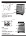
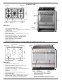
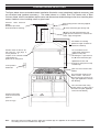
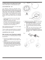
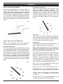
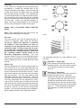
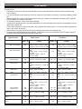
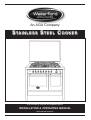
An AGA Company
S TAINLESS S TEEL C OOKER
To be installed by a trained and competent person
INSTALLATION & OPERATING MANUAL
To be left with end user
TABLE OF CONTENTS
PAGE NO.
1. Introduction . . . . . . . . . . . . . . . . . . . . . . . . . . . . . . . . . . . . . . . . . . . . . . . . . . . . . . . . . . . . . .3
2. Notes on Safety . . . . . . . . . . . . . . . . . . . . . . . . . . . . . . . . . . . . . . . . . . . . . . . . . . . . . . . . . . .3
3. Product Features . . . . . . . . . . . . . . . . . . . . . . . . . . . . . . . . . . . . . . . . . . . . . . . . . . . . . . . . . .4
4. Technical Information . . . . . . . . . . . . . . . . . . . . . . . . . . . . . . . . . . . . . . . . . . . . . . . . . . . . . . .7
5. Standard Cooker Installation . . . . . . . . . . . . . . . . . . . . . . . . . . . . . . . . . . . . . . . . . . . . . . . . .9
6. Installation Instructions (Applicable to all models) . . . . . . . . . . . . . . . . . . . . . . . . . . . . . . . . .10
Pre-Installation . . . . . . . . . . . . . . . . . . . . . . . . . . . . . . . . . . . . . . . . . . . . . . . . . . . . . . . . .10
Positioning The Appliance . . . . . . . . . . . . . . . . . . . . . . . . . . . . . . . . . . . . . . . . . . . . . . . .10
Adjusting The Cooker Height . . . . . . . . . . . . . . . . . . . . . . . . . . . . . . . . . . . . . . . . . . . . . .10
Plinth Installation . . . . . . . . . . . . . . . . . . . . . . . . . . . . . . . . . . . . . . . . . . . . . . . . . . . . . . .10
Electrical Connection . . . . . . . . . . . . . . . . . . . . . . . . . . . . . . . . . . . . . . . . . . . . . . . . . . . .11
7. Additional Installation Instructions For Dual Fuel Appliances . . . . . . . . . . . . . . . . . . . . . . . .11
Ventilation . . . . . . . . . . . . . . . . . . . . . . . . . . . . . . . . . . . . . . . . . . . . . . . . . . . . . . . . . . . . .11
Gas Connection - Natural Gas . . . . . . . . . . . . . . . . . . . . . . . . . . . . . . . . . . . . . . . . . . . . .11
Gas Connection - LPG . . . . . . . . . . . . . . . . . . . . . . . . . . . . . . . . . . . . . . . . . . . . . . . . . . .12
Converting For LPG Use . . . . . . . . . . . . . . . . . . . . . . . . . . . . . . . . . . . . . . . . . . . . . . . . .12
8. Control Panel Layout . . . . . . . . . . . . . . . . . . . . . . . . . . . . . . . . . . . . . . . . . . . . . . . . . . . . . . .13
9. Operation . . . . . . . . . . . . . . . . . . . . . . . . . . . . . . . . . . . . . . . . . . . . . . . . . . . . . . . . . . . . . . . .14
Using The Gas Hob Rings . . . . . . . . . . . . . . . . . . . . . . . . . . . . . . . . . . . . . . . . . . . . . . . .14
Using The Electric Hob Rings . . . . . . . . . . . . . . . . . . . . . . . . . . . . . . . . . . . . . . . . . . . . .14
Using The 8 Function Main Electric Oven . . . . . . . . . . . . . . . . . . . . . . . . . . . . . . . . . . . .15
Main Oven Programmer . . . . . . . . . . . . . . . . . . . . . . . . . . . . . . . . . . . . . . . . . . . . . . . . . .17
Using The Secondary Electric Oven . . . . . . . . . . . . . . . . . . . . . . . . . . . . . . . . . . . . . . . .17
Using The Rotisserie . . . . . . . . . . . . . . . . . . . . . . . . . . . . . . . . . . . . . . . . . . . . . . . . . . . .18
10. Cooking Guidelines . . . . . . . . . . . . . . . . . . . . . . . . . . . . . . . . . . . . . . . . . . . . . . . . . . . . . . . .19
11. Oven Cooking . . . . . . . . . . . . . . . . . . . . . . . . . . . . . . . . . . . . . . . . . . . . . . . . . . . . . . . . . . . .20
12. Do’s & Don’ts . . . . . . . . . . . . . . . . . . . . . . . . . . . . . . . . . . . . . . . . . . . . . . . . . . . . . . . . . . . . .22
13. Cleaning . . . . . . . . . . . . . . . . . . . . . . . . . . . . . . . . . . . . . . . . . . . . . . . . . . . . . . . . . . . . . . . . .22
14. Maintenance . . . . . . . . . . . . . . . . . . . . . . . . . . . . . . . . . . . . . . . . . . . . . . . . . . . . . . . . . . . . . .23
Greasing Taps or Thermostats . . . . . . . . . . . . . . . . . . . . . . . . . . . . . . . . . . . . . . . . . . . . .23
Changing The Oven Lamp . . . . . . . . . . . . . . . . . . . . . . . . . . . . . . . . . . . . . . . . . . . . . . . .23
Removing The Oven Door . . . . . . . . . . . . . . . . . . . . . . . . . . . . . . . . . . . . . . . . . . . . . . . .23
Other Maintenance . . . . . . . . . . . . . . . . . . . . . . . . . . . . . . . . . . . . . . . . . . . . . . . . . . . . . .23
15. Warranty . . . . . . . . . . . . . . . . . . . . . . . . . . . . . . . . . . . . . . . . . . . . . . . . . . . . . . . . . . . . . . . . .24
2
INTRODUCTION
Please read this manual carefully; it provides important information about the safety, installation, use and
maintenance of the appliance. This appliance must only be used for the purpose for which it is designed:
household cooking. Any other use must be considered improper and thus dangerous. The manufacturer cannot be considered responsible for any damage caused by improper, incorrect or unreasonable use.
CAUTION: For Dual Fuel Models, if the appliance breaks down and/or malfunctions, turn off the gas
tap, disconnect it from the electrical mains and do not tamper with it.
For any repairs, contact an authorised service agent and use original spare parts. The manufacturer
declines all responsibility in case of failure to comply with the instructions in this user manual.
The manufacturers reserve the right to make alterations to design, materials or construction for manufacturing or other reason subsequent to publication.
NOTES ON SAFETY
This cooker must always be installed by a qualified person as described in the Installation Section of this
manual.
ALL DUAL FUEL MODELS ARE CONFIGURED FOR USE ON NATURAL GAS AND IT IS THE RESPONSIBILITY OF THE INSTALLER TO CONVERT THIS APPLIANCE FOR USE WITH LPG (SEE SECTION ON
‘CONVERTING APPLIANCE TO LPG’).
a. Oven Door
Keep children away from the glass door of the oven when in use as it may cause burns when touched.
b. First Use of Electric Ovens
Operate the oven(s) empty for at least 30 minutes to eliminate any greases, fumes or impurities left by
the production cycle.
c. Warming Compartment
Never place flammable materials in the compartment under the oven.
d. Main Gas Tap (Dual Fuel Models Only)
The mains gas tap should be turned off if the cooker is not being used for an extended period of time and
the gas connection hose should be checked periodically for damage.
e. Flame Cap Covers (Dual Fuel Models Only)
The flame cap covers are purely decorative and their use does not impair the operation of the appliance.
IMPORTANT: Please retain receipt of
purchase and quote serial number for all
warranty issues.
This electrical appliance has components classified as EEEW (electrical and electronic equipment waste)
requiring selective treatment for correct ecological disposal. EEEW includes; condensers, switches, printed
circuits, electrical cables.
THIS ELECTRICAL APPLIANCE MUST NOT BE DISPOSED OF IN MIXED URBAN WASTE BUT MUST
BE SENT TO SEPARATE COLLECTION:
The purposes of Directive 2002/96/EC for differentiated treatment of EEEW are, in
particular: protecting , safeguarding & improving the environment, the protection of human
health and the expedient and rational use of natural resources.
When a new appliance is supplied, the distributor undertakes to collect this electrical
appliance and have it sent to authorised treatment centres for the disposal of EEEW.
The producer of this electrical appliance meets the requirements of Directive 2002/96/EC
by promoting and supporting the recovery, reuse and recycling of EEEW.
3
PRODUCT FEATURES
60CM ELECTRIC
Oval Extendible
Ring
600mm
Regular
Ring
Control
Panel
900
Electric
Oven
600mm
Circle Extendible
Ring
Regular Ring
FEATURES
Storage
*
*
*
*
*
*
*
*
*
Compartment
8 way function Electric Oven.
Oven capacity - 56.8 Litres [402mm (W) x 325mm (H)
x 435mm (D)]
Digital programmer & timer.
600
Internal oven light.
Control panel cooling fan - operates when oven
or ceramic rings are used.
Maximum power rating - 8,995 W or 39.1 Amps.
Height adjustable to max of 910mm.
Stainless steel finish.
Storage Compartment Capacity - 15.1 Litres [420mm (W) x 100mm (H) x 360mm (D)]
60CM GAS
Semi Rapid
Burner
60mm
600mm
Semi-Rapid
Burner
Triple Flame
Burner
Auxilary
Burner
Control
Panel
600mm
FEATURES
900mm
*
*
*
*
*
*
*
*
*
*
8 way function Electric Oven.
Oven Capacity - 56.8 Litres [402mm (W) x
325mm (H) x 435mm (D)]
Digital programmer & timer.
Internal oven light.
Control panel cooling fan - operates when oven is used.
Maximum power rating - 2,295 W or 10 Amps.
Natural Gas Configuration as standard (Refer
to section on converting for LPG use)
Height adjustable to max of 910mm.
Stainless steel finish.
Storage Compartment Capacity - 15.1 Litres. [420mm (W)
x 100mm (H) x 360mm (D)]
4
Electric
Oven
Storage
Compartment
600mm
70CM DUAL FUEL
Semi-Rapid
Burner
Semi-Rapid
Burner
600mm
60mm
Control
Panel
700mm
Rapid Burner
Triple Flame
Burner
900mm
Auxilary
Burner
Electric
Oven
FEATURES
*
*
*
*
*
*
*
*
*
*
Storage
8 way function electric oven.
Compartment
Oven Capacity - 56.8 Litres [402mm (W) x 325mm (H)
x 435mm (D)]
Digital programmer & timer.
Internal oven light.
Control panel cooling - operates when oven is used.
Maximum power rating - 2,295 W or 10 Amps.
Natural Gas Configuration as standard (Refer
to Section on converting for LPG use)
Height adjustable to max of 910mm
Stainless steel finish.
Storage Compartment Capacity - 15.1 Litres. [420mm (W) x 100mm (H) x 360mm (D)]
700mm
90CM DOUBLE OVEN ELECTRIC
Oval Extensible
Ring
Regular Ring
60mm
Control
Panel
900mm
600mm
Regular Ring
900mm
Circle Extensible Ring
Regular Ring
FEATURES
*
*
*
*
*
*
*
*
*
*
8 Function Main Electric Oven.
Main Oven Capacity - 56.8 Litres [402mm (W)
x 335mm (H) x 435mm (D)]
4 Function Secondary Electric oven
Secondary Oven Capacity - 34 Litres [220mm (W) x
325mm (H) x 475mm (D)]
Rotisserie
Digital Programmer & Timer For Main Oven
Internal Oven Light.
Control Panel Cooling - Operates when oven is used.
Maximum power rating - 12486 W or 54.3 Amps.
Natural Gas Configuration as standard (Refer
900mm
Main
Oven
*
*
*
5
Storage
Compartment
Secondary
Oven
to section on converting for LPG use)
Height adjustable to max of 920mm.
Stainless steel finish.
Storage Compartment Capacity - 30.1 Litres
[670mm (W) x 100mm (H) x 450mm (D)]
90CM DUAL FUEL
O 130mm Double
Flame Burner
Semi-Rapid
Burner
60mm
Control
Panel
900
600mm
Semi-Rapid
Burner
900mm
Auxilary Burner
Rapid Burner
FEATURES
*
*
*
*
*
*
*
*
*
*
8 Function Main Electric Oven.
Main Oven Capacity - 56.8 Litres [402mm (W)
x 335mm (H) x 435mm (D)]
4 Function Secondary Electric oven
Secondary Oven Capacity - 34 Litres [220mm (W) x
325mm (H) x 475mm (D)]
Rotisserie
Digital Programmer & Timer For Main Oven
Internal Oven Light.
Control Panel Cooling - Operates when oven is used.
Maximum power rating - 3,564 W or 15.5 Amps.
Natural Gas Configuration as standard (Refer
900
Main Oven
*
*
*
Storage
Compartment
Secondary
Oven
to section on converting for LPG use)
Height adjustable to max of 920mm.
Stainless steel or black finish.
Storage Compartment Capacity - 30.1 Litres
[670mm (W) x 100mm (H) x 450mm (D)]
100CM DUAL FUEL
O 130mm Triple
Flame Burner
Semi-Rapid
Burner
60mm
Control
Panel
900mm
600mm
Semi-Rapid
Burner
1000mm
Rapid Burner
Auxilary Burner
FEATURES
*
*
8 Function Main Electric Oven.
Main Oven Capacity - 56.8 Litres [402mm (W)
x 335mm (H) x 435mm (D)]
* 4 function Secondary Electric Oven
* Secondary Oven Capacity - 34 Litres [220mm (W) x
325mm (H) x 475mm (D)]
* Rotisserie
* Digital Programmer & Timer For Main Oven.
* Internal oven light.
* Control Panel Cooling - Operates when oven is used.
* Maximum power rating - 3,564 W or 15.5 Amps.
* Natural Gas Configuration as standard (Refer
1000mm
Main Oven
*
*
*
6
Storage
Compartment
Secondary
Oven
to Section on converting for LPG use)
Height adjustable to max of 910mm
Stainless steel, matt black or cream finish.
Storage Compartment Capacity - 18.9 Litres
[420mm (W) x 100mm (H) x 450mm (D)]
120CM DUAL FUEL
Semi-Rapid
Burner
Semi-Rapid
Burner
Semi-Rapid
Burner
Control
Panel
60mm
900mm
600mm
Semi-Rapid
Burner
1200mm
Triple Burner
Triple Burner
Auxilary Burner
Auxilary Burner
FEATURES
*
*
*
*
*
*
*
*
*
*
1200mm
8 function Main (left hand) Electric Oven.
Main Oven Capacity - 56.8 Litres [402mm (W)
x 335mm (H) x 435mm (D)]
4 Function Secondary (right hand) Electric Oven
Secondary Oven Capacity - 62.1 Litres [402mm (W) x
325mm (H) x 475mm (D)]
Rotisserie
Digital programmer & timer for main oven.
Internal oven light.
Control panel cooling - operates when oven is used.
Maximum power rating - 4,545 W or 19.8 Amps.
Natural Gas Configuration as standard (Refer to
Section on converting for LPG use)
Main Oven
*
*
*
Storage
Compartment
Secondary
Oven
Height adjustable to max of 910mm
Stainless steel finish.
Storage compartment split in two sections, each
section with a capacity of 18.9 Litres [420mm (W) x
100mm (H) x 450mm (D)]
TECHNICAL INFORMATION
BURNER
AUXILARY
SEMI-RAPID
RAPID
TRIPLE
GAS
Liquid Gas
G30
G31
PRESSURE
(mbar)
INJECTOR DIA
1/100 mm
GAS
CONSUMPTION
28..30
37
52
73 gr/h
20/25
72X
95 dm /h
Liquid Gas
28..30
37
68
127 gr/h
20/25
98
167 dm /h
Liquid Gas
G30
G31
Nat Gas G20/G25
28..30
37
20/25
88
218 gr/h
116
286 dm /h
Liquid Gas
28..30
37
96
262 gr/h
Nat Gas G20/G25
20/25
135
7
0,3000
1,750
0,440
3,000
0,750
3,600
1,500
3
Nat Gas G20/G25
G30
G31
1,000
3
Nat Gas G20/G25
G30
G31
POWER
KW
MAX
MIN
3
3
343 dm /h
TABLE OF ELECTRICAL POWERS
MULTIFUNCTION OVEN
MAIN OVEN
Waterford 60cm Dual Fuel
15 W
45 W
2265 W
2245 W
1415 W
2265 W 2295 W 1445 W
Waterford 60cm Electric
15 W
45 W
2265 W
2245 W
1415 W
2265 W 2295 W 1445 W
Waterford 70cm Dual Fuel
Waterford 90cm Dual Fuel Double Oven
15 W
15 W
45 W
45 W
2265 W
1815 W
2245 W
2245 W
1415 W
1415 W
2265 W 2295 W 1445 W
2115 W 2145 W 1145 W
Waterford 90cm Electric Double Oven
15 W
45 W
1815 W
2245 W
1415 W
2115 W
2145 W 1145 W
Waterford 100cm Dual Fuel Double Oven
15 W
45 W
1815 W
2245 W
1415 W
2115 W
2145 W 1145 W
Waterford 120cm Dual Fuel Double Oven
15 W
45 W
2265 W
2245 W
1415 W
2265 W 2295 W 1445 W
SECONDARY OVEN
Waterford 90cm Dual Fuel Double Oven
1300 W
500 W
800 W
1200 W
15 W
Waterford 90cm Electric Double Oven
1300 W 500 W
800 W
1200 W
15 W
Waterford 100cm Dual Fuel Double Oven
1300 W
800 W
1200 W
15 W
Waterford 120cm Dual Fuel Double Oven
2250 W 850 W 1400 W 1400 W
15 W
500 W
MAXIMUM ELECTRICAL POWER USAGE
COOKER MODEL
Waterford 60cm Dual Fuel
W
2295
A
10.0
Waterford 60cm Electric
8995
39.1
Waterford 70cm Dual Fuel
2295
10.0
Waterford 90cm Dual Fuel Double Oven
3564
15.5
Waterford 90cm Electric Double Oven
12486
54.3
Waterford 100cm Dual Fuel Double Oven
3564
15.5
Waterford 120cm Dual Fuel Double Oven
4545
19.8
8
STANDARD COOKER INSTALLATION
The figure below shows a standard cooker installation fitted with a steel splashback (optional accessory) and
an extraction hood (optional accessory). The model shown is a 100cm Dual Fuel Cooker with a 90cm
Chimney Hood, with the installation requirements and dimensions detailed being similar when installing other
cooker models or when installing a box or glass hood.
Extractor Hood Electrical
Supply:
Standard 3 pin socket
located behind steel ducting.
Steel Ducting fixed to wall using supplied
bracket
O 125mm Extraction pipe through wall.
200 700
O 125mm Flexible Extraction Pipe (not
supplied) connected between extractor flue
outlet & pipe through wall.
300 700
260- 280
750
Extractor Hood is fitted to the
wall using the rawl plugs &
screws provided. A
template on the extractor hood
carton details the
position of the fixing holes.
Extendable steel ducting
[Minimum height of 450mm to
maximum of 860mm]
The metal filters can be
replaced with carbon filters
(optional extras) thus
eliminating the requirement for
the O 125mm Extraction pipe.
Splashback fixed to wall
through two fixing holes on top
& bottom lips.
32 Amp Cooker
Switch Box.
Back Trim not on Electric Hob
Models.
Gas connection made on top
RHS of cooker. This can be
moved to the top LHS (Refer to
Fig.5) [Not applicable to Electric
Hob Models]
Gas connection made using
flexible gas line to allow ease of
removal of unit [Not applicable
to Electric Hob Models]
Electrical Connection
made on back LHS of
appliance.
(Refer to Fig.4)
Note:
Dimension ranges for position of power supply and extraction pipe are applicable for all extractor hood models
when fitting the unit in a standard 8 foot high room.
9
INSTALLATION INSTRUCTIONS (APPLICABLE TO ALL MODELS)
The appliance must be installed in accordance with
the regulations in force. All installation and adjustment operations must be carried out by a suitable
qualified person with the relevant national accreditation (i.e. CORGI in UK & Bord Gas in ROI).
Fig.1
The manufacturer declines all liability for any direct
or indirect damage if these regulations are not
complied with.
PRE-INSTALLATION
Prior to installing the product, the protective film
should be removed from the appliance and any
sticky residues removed using soapy warm water.
The appliance should then be checked and any
apparent defects reported to the Waterford Stanley
Service Department (051 302333 For ROI or 02887722193 for Northern Ireland)
ALL OTHER MODELS
The four adjustable feet are fixed in the four corners on the base of the appliance and can be
adjusted by screwing them clockwise or anti-clockwise (See Fig. 2). The height of the appliance is
set to the minimum of 890mm during shipping and
can be adjusted to a maximum of 910mm.
POSITIONING THE APPLIANCE
This appliance is in class 1 & class 2/1, so therefore it can stand alone or be fitted between kitchen
units, provided the following minimum distances
are adhered to:
Fig.2
* 630mm between the top surface of the appliance and horizontal surfaces above it.
* If an extraction hood is installed above the appliance, a minimum distance of 750mm must be
maintained between the top surface of the appliance and bottom surface of the hood.
* 30mm between the side of the appliance and
higher sided units. When installing the appliances between kitchen units, the units must be
able to withstand a temperature of at least
65oC and allow ease of removal of the appliance.
PLINTH INSTALLATION
(90cm Models only)
With the legs fitted, the plastic film is removed from
the plinth. The plinth brackets (stored in the oven)
are fixed to the back of the plinth and the plinth is
clipped onto the front adjustable legs.
ADJUSTING THE COOKER HEIGHT
90cm Models Only
On the 90cm Model, the four adjustable legs are
packed in the oven. On installing the cooker, the
four legs are screwed onto the base plate on each
of the four corners (see Fig.1). The height of the
appliance is then raised by turning the bottom section of the leg clockwise, whilst holding the top section. The height of the appliance can be adjusted
to a maximum of 920mm.
Fig.3
10
ELECTRICAL CONNECTION
The power cable supplied with the cooker can be
removed. Accessing the terminal block (See Fig
4), to disconnect the power cable, by removing the
back panel (i.e. remove the four self tapping
screws on each side of the panel). When connecting the new cable, ensure that it is connected to
correct terminals and fixed with the cable clamp.
Note: When carrying out any work on this
appliance, the electrical supply to it must be
isolated.
The appliance requires a 230 volt, 50Hz A.C. supply and the electrical installation must be carried
out by a qualified electrician in compliance with the
current regulations. The appliance must be connected to a cooker box control unit with a sufficient
amperage rating with maximum possible load (as
specified in the Maximum Electrical Power Table)
using an adequately sized cooker cable. The
power lead must not reach a temperature in excess
of 50oC.
Fig.4
MAXIMUM ELECTRICAL POWER USAGE
COOKER MODEL
W
A
Waterford 60cm Dual Fuel
2295
10.0
Waterford 60cm Electric
8995
39.1
Waterford 70cm Dual Fuel
2295
10.0
Waterford 90cm Dual Fuel Double Oven
3564
15.5
Waterford 90cm Electric Double Oven
12486
54.3
Waterford 100cm Dual Fuel Double Oven
3564
15.5
Waterford 120cm Dual Fuel Double Oven
4545
19.8
ADDITIONAL INSTALLATION INSTRUCTIONS FOR DUAL FUEL APPLIANCES
NOTE: ALL DUAL FUEL MODELS ARE CONFIGURED FOR NATURAL GAS AS STANDARD. IT IS THE
INSTALLER’S RESPONSIBILITY TO MAKE THE NECESSARY MODIFICATIONS (AS OUTLINED IN THE SECTION
ON CONVERTING FOR LPG) TO ENSURE THE APPLIANCE IS CORRECTLY CONFIGURED FOR USE ON LPG.
VENTILATION
GAS CONNECTION - NATURAL GAS
The room where the gas appliance is installed
must be well ventilated to allow proper gas combustion and correct ventilation during operation of
the appliance. The air flow necessary for proper
combustion must be no less than 2m3/h for each
kW of the appliance’s maximum rated power. The
maximum rated power and corresponding air flow
requirement are detailed in the table below.
This appliance should be connected using a
O12mm metal hose that complies with the National
Regulations with the connection made to the gas
connection pipe either on the left or right side of the
appliance (See Fig. 5) using an appropriate seal
between the pipe and hose. The hose must never
be more than 1.5 meters long and should not pass
behind the appliance.
Product
60cm Dual Fuel
Max Power Rating Min Air Flow
(kW)
Requirement
(m3/h)
8.1
16.2
70cm Dual Fuel
11.1
22.2
90cm Dual Fuel
11.1
22.2
100cm Dual Fuel
11.1
22.2
120cm Dual Fuel
16.2
32.4
Fig.5
When fitting an extraction hood over the appliance,
ensure that there is a permanent air vent to the
room that allows adequate ventilation for both the
hood and cooker.
11
A stability bracket must be fitted behind the appliance and connected to the stability chain connected to the back panel, as demonstrated in Fig. 5.
Fig.6
Burner Flame
Cap Cover
GAS CONNECTION - LPG
This appliance should be connected using a
O8mm metal hose that complies with IS 813 and
the connection made to the gas connection pipe
either on the left or right side of the appliance,
using clamps. When connecting to an LPG cylinder, the cylinder must be equipped with a pressure
reducer capable of supplying gas at the specified
pressure and should always follow the following
rules:
Burner Cap
* The gas connection hose must not be longer
than 1 meter.
* The pressure reducer connection must face
towards the outside of the cooker.
* The hose must not touch any hot surfaces on
the cooker or be routed behind the appliance.
* The location of the gas cylinder should be in
accordance with IS 813 & EN30-1-1.
Injector
3. Regulate the low flame setting for each burner
using the following procedure:
a. Ignite the burner and leave it in operation
on the high flame setting for one minute.
b. Turn the knob to the low flame setting.
c. Remove the knob by pulling it off the tap
shaft.
d. Using a No.2 flat-head screwdriver, adjust
the low flame setting (anticlockwise to
reduce the rate and clockwise to increase)
as shown in Fig.7. Replace the knob on the
tap shaft.
When replacing empty cylinders, the hose should
not be pulled out of position.
The gas cylinder tap should always be turned off
after use and the gas hose inspected periodically.
CONVERTING FOR LPG USE
Fig 7
Note: A complete set of LPG injectors are supplied
in the main oven. When configuring the appliance
for use with LPG, the following procedure should
be carried out:
1. Disconnect the appliance from the electrical
supply and shut off the mains gas supply to the
appliance.
2. Replace the burner injectors by removing the
burner flame cap cover, the burner cap and
unscrewing the injector using a suitable spanner. Refer to the Technical Section & Features
section to ascertain the relevant injector sizes
for each burner. (See Fig.6)
12
CONTROL PANEL LAYOUT
Main Oven
Power Light
Back Left
Ring Control
Front Right
Control Ring
Front Left
Control Ring
Digital
Programmer
Models: 60cm Dual Fuel
60cm Electric
Main Oven
Run Light
Main Oven
Thermostat
Digital
Programmer
Main Oven
Function Selector
Back Right
Control Ring
Main Oven
Function Selector
Back Left
Ring Control
Right Back
Control Ring
Main Oven
Power Light
Main Oven
Run Light
Main Oven
Thermostat
Front Left
Ring Control
Front Right
Ring Control
Models: 70cm Dual Fuel
Centre Ring
Control
Model:
90cm Electric
Main Oven
Function Selector
Main Oven
Power Light
Main Oven
Run Light
Main Oven
Power Light
Main Oven
Run Light
Main Oven
Thermostat
Back Left
Ring Control
Rotisserie
Button
Front Left
Ring Control
Front Right
Secondary
Ring Control Oven Control
Back Left
Centre
Ring Control Ring Control
Main Oven
Function Selector
Main Oven Front Right
Thermostat Ring Control
Back Right
Ring Control
Digital
Programmer
Back Right
Centre Ring
Back Left
Centre Ring
Front Left
Centre Ring
Secondary Oven
Power Light
Digital
Programmer
Secondary
Oven Run
Light
Rotisserie
Button
Secondary
Oven Control
Front Right
Centre Ring
Models:
90cm Dual Fuel SS
90cm Dual Fuel - Black
100cm Dual Fuel SS
100cm Dual Fuel Black
100cm Dual Fuel Cream
Back Right
Control Ring
Front Right
Control Ring
Secondary
Oven Run
Light
Secondary
Oven Power
Light
Models: 120cm Dual Fuel
13
OPERATION
USING THE GAS HOB RINGS
Extendible Hob Rings:
Some of the hob rings have an extendible section
(Refer to Product Features Section).
The
extendible section is operated by turning the corresponding knob to setting 9 and then rotating the
knob past setting 9 (See Fig.10). The knob is then
set to the required setting (i.e between 1 & 9). To
turn off the extendible section, return the knob to 0.
Press the corresponding gas ring knob (refer to
control panel layout) and turn it to the maximum
setting. The burner will spark and ignite. Keep the
knob pressed in for approximately 15 seconds. If
the burner fails to ignite or extinguish, wait at least
1 minute before repeating the lighting procedure.
Once the burner has remained lighting, the control
knob can be adjusted to the required setting (See
Fig.8).
Fig.10
Fig.8
High Flame
Low Flame
First Use:
When using the electric hob rings for the first time,
or if they have not been used for an extended period of time, operate them without a pan on setting 1
for 15 minutes to eliminate any moisture.
USING THE ELECTRIC HOB RINGS
During Use:
Never drag pans across the surface and always lift
pans gently onto and off the ceramic top.
Note: When operating any of the electric hob
rings, the control panel cooling fan will operate.
Standard Hob Rings:
The electric hob rings are switched on by turning
the corresponding knob to the desired setting (refer
to Control Panel Layout). The hotplate knob has
nine settings with 1 as the minimum setting and 9,
the maximum setting (see Figure 9). When a hob
ring is hot (i.e. to touch), the respective residual
heat indicator (situated on the centre of the ceramic top) will illuminate and will remain illuminated
even after being turned off until the ring has cooled
down.
Note: Spills of food that have a high content of
sugar (jam, chocolate etc) must be removed immediately as they can damage the glass. Any other
types of spills should be removed after use.
For efficient cooking, the base of the pan should be
totally flat and should be of the same size as the
hob ring diameter (refer to Product Features
Section). Pans with bowed or ridged bases or
those with an outer rim are not suitable for use on
ceramic hotplates. The following guidelines should
be used when selecting suitable pans to use:
Fig.9
Woks - Only use a flat bottomed wok and not the
conventional round bottomed type.
Pressure Cookers - Ensure that the base is flat.
Preserving Pans - Use a good quality pan with a
flat base with a diameter not greater than 250mm.
Griddles - Ensure that the base is flat and smooth
so that there is no danger the hob will be
scratched.
Frying & Grill Pans - Use a good quality pan with a
flat base and always use the larger rings.
14
Cleaning:
In the event of a spillage not being wiped clean
immediately, it should be cleaned prior to the
ceramic top being used again. Allow the hob ring
to cool and remove any debris that have burned
onto the glass using a scraper. Use a good quality ceramic hob cleaner on a damp cloth to remove
any remaining marks and wipe off any residual
cleaner with a soft damp cloth and polish with a soft
lint free cloth. Never use scouring powders or
paste, steel wool scouring pads or oven cleaners
as they may damage the surface of the glass.
Fig.11a
Fig.11b
USING THE 8 FUNCTION MAIN ELECTRIC
OVEN
Note: When operating the main electric oven, the
control panel cooling fan will operate
Fig.12
First Use:
The main electric oven can be operated either in
manual or automatic mode using the electronic
programmer. [When the appliance is powered
up initially or when the power has been reinstated to it, the programmer will be set in the
automatic mode. In order to operate the oven,
the programmer should be set to manual mode
by pressing the “cooking duration” button and
the “cooking endtime” button (Refer to the
Electronic Programmer Section]. The oven
selector switch is then set to the desired function
and the oven thermostat set to the desired temperature to operate the oven, as described in the next
section.
The following describe the eight different oven
functions:
Function 1: Oven Light
This operates the oven light only with no
cooking function. Set the function selector
to “oven light” and leave the thermostat
set to “0”.
Normal Use:
With the programmer set to the manual mode, the
oven can be set to any of the eight different functions using the oven function selector (see Fig. 11a
& refer to section on Control Panel Layout). When
one of the functions are selected, the oven power
light will illuminate. The oven heat output is then
controlled using the oven thermostat. (See Fig.
11b and refer to Section on Control Panel Layout).
The oven thermostat can be adjusted to a maximum of 270oC and the oven run light will illuminate
until the oven has reached the preset temperature.
After oven has reached temperature, the oven light
will go on and off, as the oven set temperature
requires. The oven door should remain closed during all cooking modes unless otherwise stated.
Function 2: Defrosting
This operates the oven fan with no heat circulated around the oven. Using this
method will decrease the thawing process
by roughly a third of the time but it is not
suitable for defrosting whole chickens or
large joints of meat. Set the function selector to “defrosting” and leave the thermostat
set to “0”. The food should be placed on
shelf position 3 for best results. (See
Fig.12).
15
Function 3: Static Oven
This operates the elements located on the
top and bottom surfaces of the oven. This
is suitable for baking or roasting on one
shelf only. Set the function selector to
“static oven” and set the thermostat to the
desired temperature. The food should be
placed on shelf position 3 for best results.
Fig. 14
Function 4: Fan Oven
This operates the oven fan and the oven
fan heating element in order to supply an
even spread of heat around the oven. It is
suitable for cooking cakes, large quantities
of food or to cook various dishes simultaneously. Set the function selector to
“Fan Oven” and set the thermostat to the
desired temperature. The food should be
placed on shelf position 3 when one dish is
being cooked or shelf positions 2 & 4 when
various dishes are being cooked simultaneously.
Function 6: Double Grill
This operates both the centre & outer elements of the top grill element and it is suitable for grilling underneath the entire area
of the grill (See Fig.13). The oven shelf
should be placed on the shelf position 1
with the food placed over the entire area
of the grill pan. Set the function selector
to “Double Grill” and set the thermostat to
250oC. The oven door should be kept
closed unless high water content foods are
being grilled.
Fig.13
Central Grill Area
Double Grill Area
Function 7: Double Grill with Fan
This operates both the centre and outer
elements of the top grill element and the
oven fan, thus providing heat all around
the food. This is suitable for steaks, mixed
grills or chops with the food placed on the
grill pan on shelf position 1 or 2 in the
oven. Set the function selector to “Double
Grill with Fan” and set the thermostat to
250oC.
Function 5: Central Grill
This operates the centre element of the top
grill element and it is suitable for grilling
small amounts of food. The oven shelf
should be placed on the shelf position 1
with the food placed on the centre of the
grill pan (see Fig.13). Set the function
selector to “Central Grill” and set the thermostat to 250oC. The oven door should be
kept closed unless high water content
foods such as bacon, chicken or sausages
are being grilled.
Function 8: Bottom Element with Fan
This operates the bottom element & oven
fan thus allowing for slow cooking which is
suitable for the cooking of stews and
casseroles. Set the function selector to
“Bottom Element with Fan” and set the
thermostat to the desired temperature.
The food should be placed on shelf position 3 for best results.
Note: The detachable grill handle should be used
to remove the grill pan when using any of the grill
functions. (See Fig.14).
16
MAIN OVEN PROGRAMMER
End Time” button and set the desired cooking end
time using the “-” and “+” buttons. The cook pot
symbol
is switched off. Set the function selector to the desired oven function and the oven thermostat to the desired temperature. The symbol will
appear when the programme starts and an audible
signal will sound when the programme ends.
Press the “minute minder” button to cancel the
audible signal.
Automatic Use:
Semi-Automatic Operation
This mode should be used when the oven is in
operation or if it is desired to programme its use
from the time of setting the programme. Set the
function selector to the desired oven function and
the oven thermostat to the desired temperature.
Press and hold the “Cooking Duration” time using
the “-” and “+” buttons. The “A” and the
symbols will appear on the display. An audible
signal will sound when the programme ends and
pressing the “Minute Minder” button will cancel this
sound. In order to cancel a programme, set the
programmer for manual operation by pressing the
“Cooking Duration” and “Cooking End Time” buttons. In the event of a programme being set up
incorrectly (i.e. the time of day is in between the
calculated cooking start and end times), the audible signal will sound and the symbol “A” will flash.
Minute Minder
Cooking Duration
Function Button
Cooking End Time
Decrease Set Time
Increase Set Time
Prior to using the automatic function with the main
oven, the time must be set on the digital programmer. Press and hold the “Cooking Duration” button
and the “Cooking End Time” button simultaneously, and adjust the time using “-” and “+” buttons.
The main oven can then be operated in the two different automatic modes:
Minute Minder:
The digital programmer also has a timer feature
incorporated in it. Press and hold the “Minute
Minder” button and set the desired time period
using the “-” and “+” buttons. When the time has
elapsed “ ” is displayed and an audible signal
sounds. Press the “Minute Minder” button to cancel.
Fully Automatic Operation
Press & hold the “Cooking Duration” button and set
the desired cooking duration time using the “-” and
“+” buttons. The “A” and the
symbols will appear on the display. Press and hold the “Cooking
USING THE SECONDARY ELECTRIC OVEN
(Applicable to 90, 100, & 120cm Models)
Fig. 16
The secondary electric oven is controlled using the
secondary oven control knob (Refer to section on
Control Panel Layout). This oven has five different
functions which are operated as follows:
Fig. 15
Function 1: Static Oven (Temperature Settings)
This operates the top and bottom elements in the
oven with the heat output controlled by the oven
17
Fig.18
thermostat. This method of cooking is suitable for
roasting or baking on shelf position 3 (Refer to
Fig.16). Set the control knob to the desired temperature.
Function 2: Top Element Only
This operates the top element at the maximum setting only, and is suitable for the browning of dishes.
Set the control knob to the “top element only” symbol and place the food in a suitable tray or grill pan
on shelf positioned or two.
A
B
C
Function 3: Bottom Element Only
This operates the bottom element at the maximum
setting only and is suitable for the slow cooking of
casseroles, pizzas & stews and also plate warming. Set the control knob to the “bottom element
only” symbol and place the food in a suitable tray
or grill pan on shelf position 3.
USING THE ROTISSERIE
Remove the oven shelves from the oven. Skewer
the chicken or meat with the rotisserie spit, A,
ensuring that the food is well balanced on the spit.
Place the pointed end of the spit into the rotisserie
motor coupling B situated at the back of the oven
and hook it into the rotisserie support hook, C,
located at the front of the oven. Place the oven
tray on the bottom shelf runner to catch the juices
& fats and the rotisserie rotates when the rotisserie
button is pressed. Put approx 2mm dept of water
into the oven tray to prevent fat from burning onto
it and leave the door slightly ajar. For overall cooking use function 1 with the desired temperature
selected and for overall browning select function 2.
For easy removal of the spit, screw the black plastic handle onto the end of the spit. When not using
the rotisserie, the spit can be removed from the
oven and the support hook can be stored away as
shown in Fig.19.
Function 4: Grill Element
This operates the top grill element at the maximum
setting only and is used for grilling. Set the control
knob to the “Grill Element” symbol and place the
food on the grill pan on shelf position one. the
oven door should be kept closed unless grilling
foods with a high water content. When keeping the
door open during grilling, the grill heat deflector
should be fitted into the two slots on the front to
protect the control knobs as shown in Fig. 17.
Fig.17
Fig.19
The detachable grill handle should be used to
remove the hot grill pan when finished. (See Fig.
14).
Function 5: Oven Light
This operates the oven light only and does not start
any of the cooking functions. Set the control knob
to the “Oven Light” symbol.
18
COOKING GUIDELINES
GRILLING
For fastest grilling results, the grill pan is placed on shelf position 1 and if you wish to slow down the grilling
process, position the pan on a lower shelf position. The grill pan handle should be used to move the grill pan
at all times and the oven door should be kept closed unless grilling foods with a high water content.
The following table outlines guide temperatures and times for grilling various types of food and applies to
grilling using the main oven (i.e. central grill or double grill only). The guideline times and temperatures will
vary when grilling with the small oven as it only operates at maximum setting.
Food
Pre-Heat Grill
for 5 Mins on Setting
Setting
Approximate
Cooking Time
Toasting of
Bread Products
Max
Max
3 - 10 mins
Small Cuts of Meat:Sausages, Bacon
Max
Max For 4 mins,
then reduce to 140oC
15 - 20 mins
Chops, Gammon,
Steaks etc.
Max
Max For 6-8 mins then
reduce to 100o - 140o
25 - 30 mins
Fish: Whole, Fillet,
Fingers
Max
Max
10 - 30 mins
Pre-Cooked Potatoes
Max
140o
10 - 20 mins
Pizzas
Max
140o
8 - 15 mins
19
OVEN COOKING
Cooking Hints
* Put dishes in the centre of the shelf and allow room around the dish for effective heat circulation and
even cooking.
* It is only necessary to pre-heat the ovens for food such as scones, puff pastry, Yorkshire pudding, bread
etc.
* When cooking any recipes not designed for a fan oven, reduce the temperature by about 25oC and the
time by about 10 minutes in the hour.
* To avoid fat splashes, cover meat when cooking.
* To reduce fat splashing when you add vegetables to hot fat around a roast, dry them thoroughly or brush
lightly with cooking oil.
* If you want to brown the base of a pastry dish, preheat the baking tray for 15 minutes before placing the
dish in the centre of the tray.
* When dishes may boil and spill over during cooking, place them on a baking tray.
* If experiencing condensation during cooking, preheat the oven to a temperature 20-30o higher than the
desired temperature before placing food in the oven.
Type of Food
Beef
- on the bone
(high heat roasting)
- off the bone
(high heat roasting)
Static Oven
Fan Oven
Temp (oC)
Timing
Temp (oC)
Timing
220
Rare: 10min + 15min per 500g
Medium: 10min + 18min per 500g
Well Done: 10min + 25min per 500g
180
Rare: 10min + 15min per 500g
Medium: 10min + 18min per 500g
Well Done: 10min + 25min per 500g
180
Rare: 10min + 12min at 150oC per
500g
o
Medium: 10min + 15min at 150 C
per 500g
Well Done: 10min + 20min at
150oC per 500g
o
220
Rare: 10min + 12min at 180 C per
500g
o
Medium: 10min + 15min at 180 C
per 500g
Well Done: 10min + 20min at
o
180 C per 500g
- on or off the bone
(Slow Roasting)
160
- Stuffed Joints
160
- Whole Fillet
230
- Roast
190
- Stuffed Joints
190
- High Heat Roasting
230
- Slow Roasting
- Stuffed Joints
160
160
Rare: 10min + 10min at 180oC per
500g
Medium: 10min + 15min at 180oC
per 500g
Well Done: 10min + 20min at
180oC per 500g
25min + 25min per 500g
25min + 25min per 500g
Pork
Stuffed Joints
190
190
Chicken
Duck
Goose
Veal
Lamb
Medium: 20-25min per 500g
Well Done: 30-35min per 500g
Medium: 20-25min + 5-10min per
500g
Well Done: 30-35min + 5-10min per
500g
Rare: 8min per 500g
Medium: 10min per 500g
15min + 25 - 30min at 180oC per
500g
15min + 30 - 35 min at 180oC per
500g
130 - 140
130 - 140
180 - 190
160
160
Medium: 20 - 25 min per 500g
Well Done: 30 - 35min per 500g
Medium: 20-25min + 5-10mins per
300g
Well Done: 30-35 min + 5-10min
per 500g
Rare: 8min per 500g
Medium: 10min per 500g
15min + 25 - 30min at 150oC per
500g
15min + 30 - 35min at 150oC per
500g
130 - 140
130 - 140
Rare: 10min + 10min at 150oC per
500g
Medium: 10min + 15 min at 150oC
per 500g
Well Done: 10min + 20min at
150oC per 500g
25min + 25min per 500g
25min + 25min per 500g
30min + 30min per 500g
30min + 35-40min per 500g
150 - 160
150 - 160
30min + 30min per 500g
30min + 35-40min per 500g
180
20min + 15-20min per 450g
150 - 160
20min + 15-20min per 450g
190
190
20min + 20min per 450g
15min + 15min per 450g
20
180 - 190
160
160
20min + 20min per 450g
15min + 15min per 450g
Type of Food
Static Oven
Temp (oC)
Turkey - 2.7 - 4.5 kg Birds
Timing
Fan Oven
Temp (oC)
Timing
190
20min + 20min per 450g
150 - 160
20min + 20min per 450g
190
15min + 15min per 450g
150 - 160
15min + 15min per 450g
Rabbit (up to 1 kg)
200
45-60 min
170
45-60 min
Pheasant - Hen Birds
190
45-60 min
160
45-60 min
- Cock Birds
190
60-90 min
Grouse
190
30-40 min
160
30 - 40 min
Partridge
190
30-45 min
160
30 - 45 min
Baked Fish
200
20 - 25 min
160 - 170
20 - 25 min
- 4.5 - 8 kg Birds
60-90 min
Please Note: All temperatures and times given are intended as a guide and may need to be attended to suit
the cooking requirements.
Pastries
Short Crust
Static
Oven
Fan
Oven
Bread, Scones, Cakes etc
190-200 160-170 Bread, Scones, Cakes etc
Static
Oven
Fan
Oven
230
200
Sweet Short
180
150
Sweet Bread Dough
220
190
Puff Pastry
230
200
Victoria Sandwich Cake
180
150
Rough Puff
220
190
Swiss Roll
200
170
150
135
230
200
Strudel
Flaky
Choux
180-200 150-170 Gingerbread
220
190
Scones
180-220 150-190 Rich Fruit Cake
Dundee
Meringues
Note: These are general temperature guidelines only.
21
150-170 130-150
170
140-150
120-130 100-110
DO’S & DON’TS
DO’S
*
*
*
*
*
*
*
*
*
*
DON’TS
Read the Installation & Operating Manual prior to
use.
Do operate oven(s) empty for at least 30 minutes
when using for the first time.
Do turn off the gas or electrical supply to the
cooker if it is not being used for an extended
period of time.
Do ensure that adequate ventilation is provided to
the room where the appliance is situated
(Dual Fuel Models only).
Do ensure that the appliance is correctly configured
for use with either Natural Gas or LPG
(Dual Fuel Models Only).
Do quote the product serial number when reporting
any fault with the appliance.
Do operate the hob rings on setting 1 without a pan
for 15 minutes when using for the first time.
(Electric Hob Models Only).
Do remove any spills as they occur.
Do use pans with totally flat bases and of the same
diameter as the hob ring.
Do clean the gas burner rings on a regular basis.
*
*
*
*
*
*
*
Do not place flammable materials in the storage
compartment.
Do not use scouring powders or paste, steel
scouring pads or oven cleaners when cleaning the
ceramic hob (Electric Hob Model only).
Do not remove the grill pan without the grill handle.
Do not operate the grill with the oven door open
unless grilling foods with a high water content.
Do not allow excessive condensation to build
up in the oven. In the event of condensation
being created, ensure that any condensation is
completely dried up after use.
Do not use any detergents, sponges or abrasive
cloths that may damage the coloured surfaces.
Do not use sharp items to remove stains from the
oven door glass.
CLEANING
E. Oven Door Glass
The oven door can be removed for ease of
cleaning if required. (See Maintenance
Section). The oven door exterior or interior
should be cleaned using hot water and washing
up detergent. With burned on stains on the
glass, a mild paste or cream cleaner should be
used with a soft cloth. Never use sharp items to
remove stains as they may scratch the glass.
F. Oven
For ease of cleaning, the oven shelves should
be removed from the oven. This will allow for
the two shelf runners to be removed by loosen
ing the runner fixing screw located on the bottom of the runner (See Fig.20). The bottom tray
of the oven can also be removed up through the
oven door opening.
Note: Always disconnect the electrical supply to
the cooker before cleaning.
In order to maintain the appearance of this appliance, periodical cleaning is recommended. Wipe
away any spills when they occur in order to prevent
burnt on deposits which can be difficult to remove.
A. Stainless Steel Surface
Use hot water and soap or non-chlorate
detergent, applied with a soft cloth to remove
most soiling and polish dry to avoid streaking.
For stubborn stains, use a recognised stainless
steel cleaner or stainless steel soft wool.
B. Coloured Surfaces
Use hot water applied with a soft cloth. Do not
use any detergents, sponges or abrasive cloths
that may damage the coloured surface.
C. Ceramic Hob
Refer to Page 16 - Cleaning Section.
D. Gas Hob
The pan supports can be removed and cleaned
separately using warm water. The burner flame
cap cover and the burner cap on each burner,
can also be easily removed and cleaned separately. The hob is then cleaned as outlined in the
paragraph on cleaning stainless steel surfaces
above. Ensure that all the parts are thoroughly
dried before using the hob.
Fig.20
Runner Fixing Screw
All the oven components and oven interior can
be cleaned using a recognised oven cleaner or
using a well moistened soap-impregnated steel
wool pad.
Note: The burner flame cap covers should be
cleaned after use in the event of a spillage and on
a regular basis to prevent stain build up.
22
MAINTENANCE
GREASING GAS TAPS
normal position, Fig.23b shows the hook rotated
for removing the oven door. Partially close the
door and pull away from the cooker. To reassemble follow the same procedure in the reverse order.
If a tap or thermostat becomes stiff to operate, it
must be greased as follows:
Fig.23a
- Shut off the mains gas tap;
- Remove the burners fixing screws which fix
each burner to the hob. Remove the gas tap
control knob.
- undo the two screws at the side to free the hob
and lift it.
- undo the two screws which fix the tap body C;
- remove the pin and the spring D and extract the
cone E with the aid of a pair of pliers;
- clean the cone and its seat thoroughly with a rag
soaked in solvent.
- grease the cone slightly with the appropriate
grease, put it back in place and turn it a few
times;
- remove the cone again and wipe off any excess
grease, checking that the gas passage holes
are not blocked;
- reassemble all parts carefully (See Fig.21).
Fig.23b
Fig.21
CHANGING THE OVEN LAMP
- disconnect the appliance from the electrical
mains;
- unscrew the protective cap which projects into
the oven;
- unscrew the lamp and replace it with another of
the same power and resistant to high temperatures (300oC);
- replace the cap, fitting the notches in the tangs
N, and screw down (See Fig.22).
OTHER MAINTENANCE
For any other maintenance or repair issues contact
Waterford Stanley Service Department on 051302333 for customers in the Republic of Ireland or
028-87722195 for customers in Northern Ireland.
When contacting the Service Department, please
quote your cookers individual serial number. The
serial number is located on the identification plate
which is fixed to the left hand side of the back panel
on the storage compartment door. (See Fig.24)
Fig.22
Fig.24
REMOVING THE OVEN DOOR
Open the oven door. On the hinge there is a
hook,and rotate this hook towards the cooker as
much as possible. Fig.23a shows the hook in the
23
WARRANTY
We undertake to repair or replace, free of charge to you any part found to be faulty within the 2 year
period from the date of purchase provided that:*
The fault is, in our opinion, caused by defective workmanship, or material and not by accident,
misuse, neglect or normal wear and tear.
*
Any manufacturing defect is reported to the stockist from whom you bought the appliance or
directly to Waterford Stanley Service Department within 2 years of the date of purchase.
*
The Waterford appliance is installed to the Manufacturer’s recommendations and by a suitably
qualified person.
*
The guarantee registration form is completed fully and returned to us within 30 days of the
purchase date, or proof of purchase is provided detailing the date of purchase.
IMPORTANT NOTICE: Any alteration to this appliance that is not approved in writing by Waterford
Stanley will render the guarantee void.
Manufactured by
Waterford Stanley Ltd.,
Unit 210, IDA Industrial Estate, Cork Road,
Waterford, Ireland.
Tel: (051) 302300 Fax (051) 302315
24
01Y710