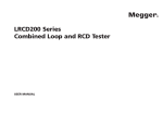
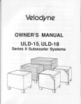
1
"If you know sub woo fers, y ou know about Velody ne." "... it's safe to say that when it comes to woofin ' done right , Velodyne's bigger models are probably the safest bet there is." n• • • we just sat there marvelling at the sheer power and majesty of this ju nior vars ity Velodyne. n -Corey Gr eenberg Hom e Theater Techn ology/February 1995 Face Off: Compa riso n of five sub woofers Model Tested: VA - 10 12X ~1 21 5xn Owner's Man ual "... Velodyn es VA- 12 15X is a great subwoofer. It combines deep , loud, high -quality outp ut with a slick styling, a fairly small cabinet, full flexibility, it's sure to stand tall next to the very best of its peers." -Tom Nousain e Video/O ctober1995 Model Tested: VA- 12 15X Velodyn e Acoustics, Inc. 1070 Com mercial St. Suite # 101 San Jose, CA 95 112 ~ @ 408.4 36.7270 voice 408.4 36. 72 76 fax Web Site: http//www.velodyne.com E-ma il: velo dyne @earthlink.net Printed on recycle d pap er. Velodyne Aud iolVideo Su bwoofer Sys tem A~A .... ~ ~ C aution To redocethe risk of electric shock,00 not rermv e cover (or back). No user-serviceable partsinside. Refer servicing to qualified service personnel. Th e lighting flash with arrowhead symbol is intended to alert the user to the presence of uninsulated ' dangerous voltage' within the prcducl's enclosurethatmay be of sufficient magnitude to ccnstitule a risk of electricshock to persons. The exclamation point symbol is intended to alert the user to the preserce of important operating ard rnalntsnarce (servicing)instn.x::tions in the Irterature accompanying the subwoofer. Read Instructions - All safety and operating instructionsshould be read be fore the subwoofer is operated. Relain Inslructions - The safely and operating instructions should be retained for future reference. Heed Warnings - All warnings on ltle subwooler and in the operating instructions should be adhered to. 4 . Follow Instructions - All operating am use instructions should be followed. 5. Water am rvIoisture - The subwoofer should not be used near water - for example, near a bathtub, washbowl, kitellen sink, laundry tub, in a wet basement, near a swimming pool or the like. 6 . Carts and Slands - The subwooter shou ld be used only with a cart or stand recommended by the manufacturer. 7 . Wall or Ceiling Mounting - The subwoofer should be mounted to a wall or ceiling only as recommended by the manufacturer. 8. Ventilation - The subwoofer should be situated so that its location or position does not interfere wiltl its proper ventilation.For exarrole , the subwoofershouldnot be situatedon a bed, sofa, rug. orsimilarsu rfacethai may block the ventilalion openings; or placed in a m ill·ininslallation such as a bookcase or cabinet that may impede the flow of air ltIrough the ventilation opening>. 9. Heat- The subwoofer should be situatedawaytromheatsourcessudl as radiators, heat registers,stoves,orother subwoorers that prodoce heal. 10_ Power Sources - The subwootershould beconnectedto apowersupplyonlyollhe typedescnbed in theope rating instructions or as marked on the subwoorer. 11_ Pow er-Cord Proteclion- Power-supplycordsshould be routedsothat ltIey arenot likelyto be walkedon or pinched by items placed upon or against them,paying particularattention to cords at plugs, convenience receptades, and the point at whidl ltl ey exit from Ule subwoofer. 12. "caution: To prevent electrical shock , match wide blade ot plug to wide slot, fully inserted.' "Attention: pou r eviler les chocs electriques,inlroduire lame Ia plus largede la fichedans Iaborne corresooooante de la prtseet pousser iUsQu' au ford." 13. Cleaning - The subwoofer should be dea ned only as recommeroed by ltIe manufacturer. 14_ Nonuse Periods - The power cord of the subwoofer should be unplugged from the outlet wtlen left unused for a long period of time. 15. Object and Liquid Entry - care should be taken so thai objects do rot fall ard liquids are not spilled onto the enclosure., 16. Damage Requirtng Service - The subwoofer should be serviced by qualified service personnel when: a. The power·supply cord or plug has been damaged. b. Objects have fallen or fiquid has been spilled into the subwoofer. c. The subwoofer has been exposed to rain. d. The subwooler docs not appear to operate normally or exhibits a marked change in performance. e. TIle subwooler has been drcpped or damaged. 17_ ServO ng - The user sboud not atterrot 10 service the sLtlwoofer beyond what is descriJed in the operating instructions. Congratulations! Congratulations on your purc hase of a Velodyne VA-121 5XII sub woofer system. T his system represents the state of the a rt in accurate low frequency reproduction. Read and follow the instr uc ·tions below to insure safe and prop er system operat ion. Warning! To prevent fire or sh ock hazard, do not exp ose this eq uip ment to rain or mois ture. To avoid ele ctrica l sh ock, do not open sp eaker enclosure or amp chassis cover. Please obs erve all warnings on the equipment itse lf. There are no user se rviceable parts inside. Please refer all se rvice questi ons to yo ur authorized Velodyne dea ler. 1. 2. 3. All other servicing should be refened to qualifiedservice personnel. Prior to installation Please unpack the system carefully . Remove all staples used to seal the carton as they can scratc h the cabinet. Please save the carton and all packaging mate rials fo r future use. Record the ser ial number in the space provided on the warrant y card fo r future referen ce . Product Features & Controls • 12" forward firing woofer with 2" voice coil & 55 oz. magnet • 15" downward firing passive radiator • Built-in 250 watt (RMS) power amplifier • Adjusta ble (40 to 120hz) low-pass cross over with bypas s option • Selectable (80 or 100hz) high-pas s crossover • Line-level inputs & outputs • Speaker-level inputs & outputs with 5 way binding post connec tions • Signal sensing auto turn on/off with bypass option • Variable volume control • Variable phase contro l (0 to 180 degrees) • Two position audio/video listening selection switch (+3dB, vide o) • Response, 22 hz to 120 hz, +/- 3dB • Detachable power cord (avai labl e on some versions) • Magnetically shielded for video use • Dual staggered low-pass crossover; 12dB/octave initial, 24dB/ octave ultimate • Gain com pression circuit to protect woofer from over excursion • Input ov erload protection • Th erm al power sensing to protect woofer's voice coil from burnout • Power on LED (green) You should set the crossover frequency to obtain a smo oth a nd sea mless transition from the subwoofer to the main speakers in yo ur system. If your main speakers are small er units with limited low frequency output, you may wish to choose a higherf requency (such as 100-120hz) than you would with larger speakers which have greater low frequency output. With larger speakers, you might start with this con trol set lower, such as 80hz. Installation A bypass switch is also provided if you wish to use an external crossover. If you are not using an externa l crossover, we recom mend that you use the one provided with in the unit for optimum performance. Your new VA-1215XII subwoofer system provides for a number of installation options. Read all the installation information below in order to dete rmine which installation option is best for your system. Rem em ber to perform all in stall at io n procedures with system power turned off. Inp uts Your new VA-1215XI I subwoofer is equ ipped with both speaker level and line-leve l inputs. Use the LINE -IN jacks when connecting your subwoofer to a pre- amp, signal processor, or line-level cross over. The FRO M AMPLI FIER jacks connect directly to the speaker outputs of a integrated amplifier or receiver. Your amplifier section will notice no additional loading effects when you use these inputs because of their high impedance. Note 0 0 n ot use bo th LIN E-IN and FROM AMPLIFIER inp uts simuue neously . Volume control This co ntro l allows you to bala nce the output from the subwoo fer to the mai n speakers in you r system. Th is control should be set to achieve simila r volume level from both the main speakers and subwoofer. Low-pass crossover Both sets of inputs sum the left and right channels toge ther and the resulting signal is passed through an adjustable low-pass crossove r before being amplified . Th e crossover control allows you to adjust the upp er limit of the subwoofer's frequency response from 40 to 120 hz. Th e subwoofer's 'response will begin rolling off above the frequency you set this control to. Phase adjustment This control allows you the ability to compensate for having the subwoofer in a different location than the main speak ers. Ideally, you will have the sound from the subwoofer reach the listening position the same time as the sound from the main speake rs. However, if the distance from the listening position to the subwoofer and the distance from listening position to the main speakers diffe rs, the sound from each will reach your ears at adltterent time . This control allows the signal to be delayed up to 180 degrees so th e output of the subwoofer will blend in to that of your main speakers without any canc ellation. Vi deo/Audio swit ch Many listeners prefer an "emphasized" low end on mo v ie soundtracks. This switch sets the VA-1215XII for an additional 3dB of output when in video mode . Auto t urn on switc h The auto turn on switch allows the user to bypass the auto turn o n function if desired. Wh en set in the "auto" mode with main power o n, the VA-1215XII will turn itself on when an input signal is present. If no signal is present, after several minutes the unit will shut itself off. Whe n set in the "on" mode, the auto turn on/off function is byp assed and the unit will be on wheneve r the main power switch is on. Hi g h pass crossover switch This switch selects the frequency for the high pass crossove r. This cross over is functional on both line and speaker-level outputs. Smaller speakers with limited low frequency output may prefer the cca tiaued.. . . higher 100hz setting which will reduc e the low frequencies sent to them . Larger speakers wit h greater low frequency output may be able to handle the 80hz selli ng witho ut strain. A word about subwoofer outputs The Velodyne subwoo fer is designed to operate using the full range audio signal for input when using the built-in crossover. Some surro und sound processors/receivers, including the Dolby AC3 sys tem with there .1 channel outputs, have a "subwoofer out" jack that is already crossed over and designed to be used with a conve ntional amplifier and speaker. Combining both an external crossover and the one internal to the subwoofe r may result in low output and increased noise . In these cases, to optimize your subwoofer pe rformance you should bypass the intern al cross over in your Velodyne subwoofer. Power switch Th e ma ster power switch is located on the right half of the unit. This rocker style switch is the mai n on/off for the unit. This switch should be set to position 1 for on (up) , 0 for off (down). Det achable power cord (available on some versions) Allows for easy replacement should the original be damaged. ~ Line-level connection Figure 1 shows connection to a pre-amplifier's main outputs and returning them to your amplifier inputs. Note If not using an external crossover, you should use the built-in crossover for optimal performance. W ~ e n installed in this fashion, your satellite speakers will be crossed over at 80/1OOhz which remove s the lower bass from your amplifier and speakers, enab ling them to do a better job reproduc ing high frequencies. By utilizing this method, you will have a bi amplified system, gaining improved power and headroom for your syste m. Subwoofer out from AN Processor From the low pass output of your signal processor Install into right or left RCA line in connector in the back of the subwoofer or use a "Y!' connector adapter into both right and left RCA line in connectors in the back of the subwoofer. Figure 1: Installation using lin e-l evel (line in) inputs / .-0_ .. . " ~~_ ....- "'Co....-. II c.'J1C:.tJ:l. J_::._9~ _~O~~ O _ F'OHl" ••• ,.. ttl). ~ 1 '@'@r@-@ ,.. -, Velodyn e ... =@ @J r=-'_on- - = @@@@ ~ « To bypass the crossover within the subwoofer, simp ly locate the switch marked "normal/bypass" on the back panel of the subwoofer and set to the "bypass" position . This will eliminate the internal crossover function. "" ~=::~ .;~ft --- Speaker-level connectio ( _n_ ) @ ) ~....:::-: :-.:-- \ ~. " Figure 2 shows an easy way to connect your VA-1215XII subwoofer directly to your receiver or integrated amplifier. ./ AMPLIFIER PRE-AMP MAIN OUTPUTS LEFT RIGHT MAIN IN PUTS RIGHT LEFT <f ~ "" TO MAIN OUTPUTS RIGHT LEFT ~!> ~!> ~ ~ ~~ a.TELLITE SPEAKERS When connected in this fashion, your satellite speakers will be crossed over at 80/1OOhz, which removes the lower bass from your speakers thus, enabling them to do a better job reproduc ing high frequencies. You may also conn ect your satellites directly to your receiver or amplifier along with the subwoofer if you wish to bypass the internal high-pass crossove r. continued. . Figu re 2: Installation using speaker-level (from amplifier) inputs -_. / N~ ~"oo. ~ _A" II .'oGr&:t. ~.~lliJt._o: ~: G'==~ G.__ ., Velodyne ~Ei=r ~;t11 0;ft 10_ ....... EI ION"" •• •• 0 ~_ .. I - ,,- I 'f,j-~!i·~1i·W [~~rn!r ® @ system condi tions often dictate otherwise. See your dealer for he lp in placement. --=_ C;:~. :'" ~ \.. When using a pair of VA-1215XII subwoofers in stereo, it is prefe rable to place each subwoofer adjacent to the satellite of the same channel. Keep in mind that freq uency response and output level can be drastically influenced by plac ement dep ending on the acoustic propert ies of the listening room. Typically the VA-121 5XII will sound louder when placed next to a wall or in a corn er. L. L-.., ~ @ ~~ ~ ~ MA IN O UTPUTS (sp eak er -l ev el) INT EGR ATE D AMP I RECE IVER ~~ (~ ~~ @ S A T E L LI T E SPEAKERS Cau t ion ! To a void damage to your main amplifier, be sure to maintain correct pola rity when ma king a/l conn ections . Red (pos itive) to red, and black (negative) to black. Be sure that a/l connections are tight, and that there are no loose strands or frayed wires. Caution! The VA series subwoofers have amp lifiers built int o the cab ine t. 0 0 not place the cabinet next to sources of heat such as furnace registers , radiators, etc. The p ower cord should be routed in such a way that it will not be walked. on, pinched, or comp ressed in any way. Regardless of where you install your VA-1215XII subwo ofer, it mus t remai n in an upright positi on (passive rad iator fa cing downward) . Using, shipping , or oth erw ise storing the VA-1215X II subwoofer in any other position for an extended period of tim e may result in damage to the unit not covered by warranty. When install ing your VA-121 5XII using the lin e-level inputs/outputs, you shou ld use standard shielded phono ca bles. Always keep th e lines as short as practical to minimize noise. The VA-121 5XII Subwoofer is magnetica lly shie lded to reduce magnetic emission from its cab inet to increase the number of possible locat ions ava ilab le for placement. However, this shiel ding may not be adequate for all installations. Certain typ es of te levisions are particularly sensitive to stray magnetic fields. If your television produces disto rted colors after installation of your VA-12 15XII . subwoofer , simp ly increase the distance between you r television and the VA-1215XII until nor mal color and operatio n is returned. Whef)..us ing the speaker-level inputs/outputs, use the same quality speak er cable to your subwoofer as you run to your satellites. Care 0 Placement Do not use any harsh detergents or chemicals to clean the ca binet. Abrasives, dete rgents, or clean ing solutions may damage the finish on the cabinet. We recommend using a damp cloth to cle an the cabinet. The VA-1215XII operates at very low frequencies which are prima rily non-directional. While it is recom mended th at the subwoofer be placed on the sam e plan e as the satellit e speakers, room and During normal conditions. the VA-1215XII subwoofermay be lett on Interconnect cables our subwoofe continued. . . continuou sly with out any problem s. T he unit is equ ipp ed w ith a signal-sensing turn on/o ff th at wi ll au tomatically tu rn on the unit when a signal is present at the inputs and turn off the unit after several mi nutes wh en there is no lon ger any signal at the inputs. If you plan to leave th e VA -1215XII unused for an extended period of time, w e reco mmend that yo u turn off th e unit by the master power switc h on the rear panel. SPECIFICATIONS VA-1215XII Cabinet (inc!. legs) 18" x 19-1/8" x 20" (W,H,O) Frequency Response 22hz - 120hz +/- 3 dB High Pass Crossover 80hz or 100hz (6 dB/octave) Low Pass Crossover 40hz - 120hz (6 dB/octave, 24 dB ultimate) Troubleshooting & Service Amplifier Before seeking service for your VA-1215XII subwoofer, please re check all systems. Following is a simple troubleshooting guide to assist you. 1. 2. 3. 4 . 5. Ve rify unit is plugged in and power outlet used is active . Is pow er switch on? Is auto turn on/off set properly? Is unit receiVing an input signal from your source? Have all controls on subwoofer (volume, crossover, phase , etc .) been properly set? 6. If un it has been running at high levels, one of the protection c ircuits ma y be engaged. Has the b uilt-in amplifier overheated? Has the speaker's voice-coil started to heat up? If the p rotection circuitry is active, the unit may cycle on and off until op eratin g para meters return to normal. Under more serious condi tions , th e unit may shut off completel y. Normal operation will return upon cooling, but you may be require d to turn the power off and then on a gain to reset the unit. The fo) low ing condit ions require service by a qualified technician : peak Woofer 12" forward firing Magnet 55 oz. Voice Coil 2" Passive Radiator 15" downward firing Inputs Line-level & speaker-level Outputs Line-level & speaker-level Warranty One year (parts & labor) Weight 67 Ibs. (approx.) Specifica tions are subje ct to change without notice. FOR YOUR RECORDS. . . DATE PURCHASED 1. T he pow e r cor d has bec ome damaged. 2. The un it does not appear to operate norma lly or exhibits a marked change in performance. 3. The unit has bee n exp osed to water. 4 . Some part of the cabinet or ci rcuitry is physically damaged. Thank you for purchasing a Velodyne! Class AlB, 250 watts, 500 walts _ DEALER SERIAL # _ _ 'N OTE: Please comp lete and return your warranty card within ten ( 10) days.