1
SNMP Solo
™
Owner’s Manual
for:
SNMP Solo™
by:
MT-SE-37/02
12-DEC-99
Copyright © 1999
93-1469 (9909097) 12/99
Limited Warranty
Tripp Lite warrants that each product sold by Tripp Lite is compatible with existing
commercially available computer operating environments and is free from defects in
materials and workmanship under normal use. This warranty is applicable only to
the initial end user (END USER), and is not transferable. The duration of this
warranty is one (1) year from the date of the first retail sale or the date of delivery to
the PURCHASER, whichever occurs first, subject to the following conditions.
If the PURCHASER discovers within the duration of this warranty a failure of the
product to perform compatibly with presently existing computer equipment or a
defect in material or workmanship, the PURCHASER must promptly notify Tripp Lite
in writing within the duration of the warranty. Tripp Lite’s obligation under this
warranty is limited to the replacement or repair, subject to the conditions specified
below, of such product returned intact to Tripp Lite which shall appear to Tripp Lite,
upon inspection, to have been either incompatible or defective. Replacement or
repair will be made at Tripp Lite’s Technical Support Center. Such repair or
replacement shall be at Tripp Lite’s expense. This warranty does not cover any
taxes which may be due in connection with replacement or repair, nor any
installation, removal, transportation or postage costs. These expenses will be paid
by PURCHASER. If Tripp Lite is unable to repair or replace the product to conform
to this warranty after a reasonable number of attempts, Tripp Lite will refund the
purchase price to the purchaser or dealer product was sold through. Remedies
under this warranty are expressly limited to those specified above.
TO THE EXTENT ALLOWED BY LAW, TRIPP LITE DISCLAIMS ALL OTHER
WARRANTIES, EXPRESS OR IMPLIED, INCLUDING, BUT NOT LIMITED TO,
ANY IMPLIED WARRANTIES OF MERCHANTABILITY OR FITNESS FOR A
PARTICULAR PURPOSE, AND ANY IMPLIED WARRANTY OF MERCHANTABILITY OR FITNESS FOR A PARTICULAR PURPOSE ON THIS PRODUCT IS
LIMITED IN DURATION TO THE DURATION OF THIS WARRANTY. TO THE
EXTENT ALLOWED BY LAW, TRIPP LITE SHALL NOT BE LIABLE FOR ANY
SPECIAL, INCIDENTAL, OR CONSEQUENTIAL DAMAGES INCLUDING, BUT
NOT LIMITED TO, LOSS OF PROFITS, INJURIES TO PROPERTY, LOSS OF
USE OF THE PRODUCT OR ANY ASSOCIATED EQUIPMENT.
Some states do not allow limitations on how long an implied warranty lasts, so that
the above limitation on duration of implied warranties may not apply to you. Some
states do not allow the exclusion or limitation of incidental or consequential
damages, so the above limitation or exclusion may not apply to you. This warranty
gives you specific legal rights, and you may also have other rights which vary from
state to state. You are advised to consult applicable state laws.
No warranty is made with respect to other products sold by Tripp Lite which do not
bear the name Tripp Lite, and no recommendation of such other product shall imply
or constitute any warranty with respect to them. The warranty does not apply to
products which have been abused, mishandled, modified, damaged, by act of God
or a source external to the product; repaired by others; or which have their serial
numbers removed or altered.
Please register your unit by completing the Warranty Registration Card enclosed
with your product. Should you need to make a claim, please contact your dealer or
Tripp Lite; giving the serial number, date of purchase and details of the fault.
Governing Law
This statement shall be construed, interpreted, and governed by the laws of the
State of Illinois.
YOU ACKNOWLEDGE THAT YOU HAVE READ THIS AGREEMENT,
UNDERSTAND IT AND AGREE TO BE BOUND BY ITS TERMS AND
CONDITIONS. YOU FURTHER AGREE THAT THIS IS THE SOLE AGREEMENT
BETWEEN US AND SUPERSEDES ANY PROPOSAL OR AGREEMENT ORAL
OR WRITTEN BETWEEN US RELATING TO THE SUBJECT MATTER.
(Some states do not allow the exclusion or limitation of liability for consequential or
incidental damages, so the above limitations may not apply to you.)
FCC Compliance
SNMP Solo has been tested and found to comply with the limits for a Class A digital device,
pursuant to Part 15 of the FCC Rules. These limits are designed to provide reasonable
protection against harmful interference when the equipment is operated in a commercial
environment.
This equipment generates, uses, and can radiate radio frequency energy; and, if not installed
and used in accordance with the instructions, may cause harmful interference to radio
communications. Operation of this equipment in a residential area is likely to cause harmful
interference in which case users will be required to correct the interference at their own
expense.
CHANGES OR MODIFICATIONS TO THIS EQUIPMENT NOT EXPRESSLY
APPROVED BY THE MANUFACTURER COULD VOID YOUR AUTHORITY TO
OPERATE THE EQUIPMENT.
Copyright 1999 by:
Tripp Lite
Printed in USA
Unauthorized reproduction prohibited.
Trademarks
SNMP Solo is a trademark of Tripp Lite.
IBM, IBM NetView/6000 are trademarks or registered
trademarks of International Business Machines Corp.
Hewlett-Packard, HP, HP Open View are trademarks or
registered trademarks of Hewlett-Packard Company.
Microsoft, MS, MS-DOS, XENIX are registered trademarks and
Windows, Windows NT, LAN Manager, and Win32 are
trademarks of Microsoft Corporation.
NT is a trademark of Northern Telecom Limited.
Novell and NetWare are registered trademarks, and NLM is a
trademark of Novell, Inc.
SunConnect SunNet is a trademark or registered trademark of
Sun Microsystems Computer Corporation.
Xerox is a registered trademark of the Xerox Corporation.
Conventions Used In This Guide
This guide uses these conventions:
Bold italic print, as shown in this example, indicates field
names, menu items, or values in the SNMP Solo software
agent.
Bold print, as shown in this example, indicates filenames,
directories, or items that you must type exactly as they appear.
Italic print words or letters in braces { }
indicate values that you must supply. For example:
{drive}:\setup
Italic print words or letters in brackets < > indicate keys to
press. If two keys are separated by a + plus symbol, then the
first key should be pressed and held down while pressing the
second key. For example: <alt+enter>.
Note:
Warning:
Notes contrast from the text to emphasize their importance.
These messages alert you to specific procedures or practices;
serious consequences may result including injury if you disregard
them.
Tripp Lite
Table of Contents
Introduction ............................ 1
SNMP Solo Features ............................ 1
Example Network With SNMP Solo............... 2
SNMP Solo Package ....................... 3
SNMP Solo Package Contents ....................
The SNMP Solo Unit...........................
Status LEDs ................................
DIP Switches ...............................
Serial Port ................................
Two 3.5” Diskettes ..........................
Configuration Cable..........................
Power Supply.................................
UPS Interface Cable..........................
3
3
4
4
5
5
5
5
6
System Requirements ..................... 7
Initial Installation .................... 9
Verify The SNMP Solo Operation.............. 10
Configuration .......................... 11
Set IP And Gateway Addresses
And MIB System Group ......................
Set Access Controls ..........................
Set Trap Receivers ...........................
Additional Setup Screen ......................
Display Settings .............................
Reset Configuration to Default ...............
To Save and Exit .............................
Telnet Options ...............................
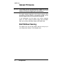
Upload Firmware ..............................
Exit Without Saving ..........................
12
15
16
18
18
20
20
21
22
22
Final Installation ..................... 23
Verify The SNMP Solo Operation ............... 23
Establish Network Communications ............. 24
Configuring the NMS .................... 25
General Network Management Stations .......... 25
HP OpenView Network Node Manager for HP-UX.. 25
Table of Contents
i
SNMP Solo
Compile the Device MIB ....................
Add SNMP Solo Object to the Management Map..
Poll the Device OIDs ......................
Set the Device OIDs .......................
Ping the SNMP Solo ........................
Novell’s NetWare Management Station v.2.0...
Compile the Device MIB ....................
Add SNMP Solo Object to the Management Map
Poll the Device OIDs ......................
Set the Device OIDs .......................
Ping the SNMP Solo ........................
SunConnect SunNet Manager...................
Compile the Device MIB ....................
Add SNMP Solo Object to the Management Map
Poll the Device OIDs ......................
Set the device OIDs .......................
Ping the SNMP Solo ........................
25
25
26
26
26
26
26
27
27
27
27
28
28
28
29
29
29
Appendix ............................... 30
Reference ....................................
Communities.................................
IP Addresses................................
Subnetting and Subnet Masks.................
Gateways....................................
Glossary .....................................
Troubleshooting ..............................
Placing a Technical Support Call .............
30
30
30
31
32
33
35
36
Reference Worksheet .................... 38
TABLE OF FIGURES
Figure 1 SNMP Solo Monitoring a UPS on EtherNet ................. 2
Figure 2 SNMP Solo Network Connection Panel....................... 3
Figure 3 SNMP Solo Serial Port Panel....................................... 4
Figure 4 Communication Screen (Windows)............................. 10
Figure 5 Main Menu.................................................................. 11
Figure 6 IP Address for the SNMP Solo and More .................. 12
Figure 7 Access Controls ......................................................... 15
Figure 8 Trap Receivers ........................................................... 17
Figure 9 Additional Setup Screen............................................. 18
Figure 10 Display All Current Settings ..................................... 19
Figure 11 Reset Values To Default ........................................... 20
Figure 12 Save and Exit Messages For Configuration.............. 20
Figure 13 Telnet Options ........................................................... 21
ii
Introduction
Tripp Lite
Introduction
Your SNMP Solo monitors one UPS attached to an EtherNet
network using a Network Management Station. The complete
SNMP Solo package includes hardware and software, a UPS
cable, a power supply, a UPS Management Information Base
(MIB), and a manual.
SNMP Solo Features
The SNMP Solo hardware adapter runs an embedded Simple
Network Management Protocol (SNMP) software agent. This
agent responds to SNMP GETS and SETS and, also, forwards
traps to designated recipients when critical conditions occur to
the UPS—such as going on battery backup.
The SNMP Solo features:
• Compact Size—A small unit that takes less space on your
work area. Dimensions are 4¾”x3½”(12 x 8½ cm).
• One Serial Port—A DIP switch changes the adapter’s
single serial port to a configuration port for installation or to
a communication port for normal operations.
• Remote monitoring—Monitors utility power and low
battery status for one UPS from a remote workstation
(NMS).
• Remote Control—Turns the UPS inverter off when the
NMS sends the proper command.
• NMSs To Receive UPS Alarms—These traps (unsolicited
messages) inform you about the power condition of your
UPS.
• Works with all major NMSs on EtherNet—SNMP Solo
works with the most widely used Network Management
Systems: HP Open View, Novell NMS, Sun NetManager,
IBM NetView, and many more.
Introduction
1
SNMP Solo
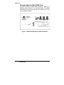
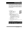
Example Network With SNMP Solo
A typical installation of SNMP Solo monitoring a UPS on an
EtherNet network follows in the illustration below. The SNMP
Solo adapter communicates with the UPS to inform you of your
system’s power condition.
SNMP Solo
Figure 1 SNMP Solo Monitoring a UPS on EtherNet
2
Introduction
Tripp Lite
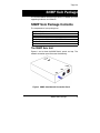
SNMP Solo Package
The standard SNMP Solo package contains a NetMon Unit with
supporting hardware and software.
SNMP Solo Package Contents
The components of your package are:
!
!
!
!
!
!
!
SNMP Solo Unit
Two 3.5“ Diskettes
Power Supply
SNMP Solo Manual
Configuration Cable labeled SM-SER-117A
UPS Interface cable
Worksheet included in the Manual
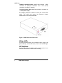
The SNMP Solo Unit
Figures 2 and 3 show the SNMP Solo’s panels and top. The
network connection panel illustrates the following:
Figure 2 SNMP Solo Network Connection Panel
SNMP Solo Package
3
SNMP Solo
Network connection ports—SNMP Solo provides a BNC
connector for 10Base-2 connection and a UTP (RJ-45)
connector for 10Base-T networks.
Power connection port–SNMP Solo provides a connector for
a 9VDC power supply.
The following illustration shows the serial port and the DIP
switch. The serial port serves two purposes—adapter
configuration and UPS communication.
Figure 3 SNMP Solo Serial Port Panel
Status LEDs
The LED indicators inform you of network activity, which is the
green LNK light, and the UPS status, which is the red ERR light.
DIP Switches
Use the DIP switch to configure with a dumb terminal or to
communicate with the UPS for status monitoring.
4
SNMP Solo Package
Tripp Lite
Serial Port
The SNMP Solo uses this port for configuration during
installation or for communications during normal operations.
Two 3.5” Diskettes
Your package contains two 3.5” MIB diskettes—one in DOS
format and one in TAR format. These diskettes contain the UPS
MIB file. Copy the MIB file to the appropriate NMS MIB
directory for the UPS connected to your SNMP Solo.
The DOS disk also contains a copy of the programmed image
file and the downloaded .exe program. See the Upload
Firmware section for further explanation of these files.
Configuration Cable
Your package contains a cable labeled SM-SER-117A, femaleto-female. Use this cable to connect the SNMP Solo serial port
and a dumb terminal or PC for configuration. When you
configure the SNMP Solo, be sure to set the DIP switch to the
proper setting. Any dumb terminal or terminal emulation
package, such as Microsoft Windows’ Terminal will work fine.
Power Supply
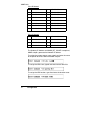
The two types of power supplies offered are:
Power Supply Type
Wall Cube
Universal
Input
120 VAC, 60 Hz
230 VAC, 50 Hz
Output
9 VDC, 1 amp
9 VDC, 1 amp
WARNING: If you are using a power supply other than the one supplied
with the SNMP Solo, be sure that the polarity of the new
power supply is correct. If the polarity of the new power
supply is incorrect, you may run the risk of damaging the
adapter.
SNMP Solo Package
5
SNMP Solo
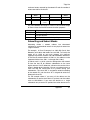
UPS Interface Cable
The manufacture-specific interface cable connects the UPS to
the SNMP Solo unit. The table below defines the basic UPS
device port configuration:
1
2
3
4
5
6
Low Battery
Not Connected
Set to Voltage Low (-12 V)
Inverter Shutoff
Ground
SNMP Solo Package
6
7
8
9
Not connected
Set to Voltage High (+12V)
Power Fail
Not connected
Tripp Lite
System Requirements
SNMP Solo requires a terminal for configuration and a network
connection with an NMS for operation. The following is a
description of all required components and a list of the most
widely used NMSs.
• The components of your standard SNMP Solo package
• Connection to an EtherNet network
• An SNMP-based management station
Some NMSs that support the SNMP Solo are:
•
•
•
•
HP OpenView for UNIX
HP OpenView for Microsoft Windows
Novell NMS
SunConnect SunNet Manager
IBM NetView/6000
A dumb terminal or a PC with an emulation package to
configure the SNMP Solo SNMP Agent
An RS232 communication port on your PC or terminal
A UPS—any UPS type
You can interface any contact closure UPS with SNMP Solo
if you have the manufacture’s specific cable supplied with
your kit.
Network identification values for the SNMP Solo:
IP Address
Net Mask
IP Addresses for the NMS
Definitions of Communities
IP Address of the Gateway/Router
System Requirements
7
SNMP Solo
8
System Requirements
Tripp Lite
Initial Installation
This section describes the installation of the SNMP Solo
adapter when you connect it to the UPS and the network. (Refer
to the Configuration section for network communications’
setup.) For configuration, connect the SNMP Solo temporarily to
a PC with a terminal emulation package or to a dumb terminal.
The following steps guide you in connecting the SNMP Solo to
the network and UPS.
1. Install the UPS.
2. Adjust the DIP switches on
the
SNMP
Solo
for
Configuration. Switch 1 is
ON when down; switch 2 is
OFF when up.
3. Temporarily, connect the SNMP Solo
adapter to a dumb terminal or to a PC with
the terminal emulation package.
a) Using the configuration cable, connect the
end of the cabled labeled “SM-SER-117A”
into a dedicated RS-232 serial port on the
configuration PC.
b) Connect the other end into the SNMP
Solo’s serial port.
4. Configure the communications settings.
a) Use the following settings to configure the dumb
terminal or PC.
Baud rate ! 9600
Data bits ! 8
Stop bit ! 1
! None
Parity
Flow Control Xon/XOFF
Handshaking ! None
Terminal Type:! ANSI (VT100)
! Off
Local Echo
Initial Installation
9
SNMP Solo
b) A Windows’s communication screen with the typical
SNMP Solo setting:
Figure 4 Communication Screen (Windows)
5. Press OK if you have the Windows Communications
screen or accept your communication settings in the
terminal emulation package. The terminal is now
configured to communicate with the SNMP Solo
adapter.
6. Connect the power supply with the 9VDC connector to
the SNMP Solo adapter’s power input. Connect the
other end of the power supply with a standard plug into
the UPS. Approximately five seconds after you supply
power, the adapter displays the introductory screen on
your terminal. Press <enter> to get to the main menu.
7. You are now ready to configure the SNMP Solo
adapter. Refer to the Configuration section for a
detailed discussion.
10
Initial Installation
Tripp Lite
Configuration
You have previously installed the UPS, and you are ready to
configure the SNMP Solo to work on your network. SNMP Solo
is temporarily connected to a PC with a terminal emulation
package or to a dumb terminal.
NOTE:
Refer to the Installation section for the proper setting of the
hardware adapter prior to configuring the device.
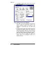
Press any key to display the Main Menu. From this menu you
can select to enter the IP address, Gateway address, and MIB
system group; you can set the access controls of SNMP
communities; set traps, display settings; reset the settings to
default values; save the new values and exit the program, and
upgrade Firmware (See caution in the Upgrade Firmware
section); and exit without saving.
Figure 5 Main Menu
To select any option on the Main Menu, enter the number of the
option you want at the Choose a Number=> prompt. The
program displays the desired screen.
Configuration
11
SNMP Solo
Set IP And Gateway Addresses
And MIB System Group
To set the IP address, Gateway address, MIB system group,
and other system configurations, type 1 at the prompt. The
following screen displays:
Figure 6 IP Address for the SNMP Solo and More
NOTE:
The minimum requirement to operate SNMP Solo is to set
the IP address.
To enter values, enter the number of the option, type a
<space>, and enter the name. Press <enter>. Your new value
displays next to the field heading on the top of the screen.
If you want to return to the Main Menu, press 0 (zero) and press
<enter>.
For more information on IP addresses and net masks, see the
Reference section of the Appendix in this manual.
12
Configuration
Tripp Lite
To assign the IP address of SNMP Solo, the gateway, and the
network, type at the prompt:
1, <space>, the IP address of the SNMP Solo, <space>,
MASK_BIT_COUNT, <space>, the IP address of the gateway.
The MASK_BIT_COUNT is used to indicate a mask for your
gateway.
The meaning of the numbers used in the
MASK_BIT_COUNT will change based on the class of network
you have. A Class A network has 24 options, a class B network
has 16 options and a Class C has 8 options. The SNMP Solo
automatically discovers the type of network in use from the first
three digits of the IP address. The MASK_BIT_COUNT and the
corresponding mask for each type of network is shown below.
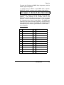
Class A Network
0
255.000.000.000
12
255.255.240.000
1
255.128.000.000
13
255.255.248.000
2
255.192.000.000
14
255.255.252.000
3
255.224.000.000
15
255.255.254.000
4
255.240.000.000
16
255.255.255.000
5
255.248.000.000
17
255.255.255.128
6
255.252.000.000
18
255.255.255.192
7
255.254.000.000
19
255.255.255.224
8
255.255.000.000
20
255.255.255.240
9
255.255.128.000
21
255.255.255.248
10
255.255.192.000
22
255.255.255.252
11
255.255.224.000
23
255.255.255.254
Configuration
13
SNMP Solo
Class B Network
0
255.255.000.000
8
255.255.255.000
1
255.255.128.000
9
255.255.255.128
2
255.255.192.000
10
255.255.255.192
3
255.255.224.000
11
255.255.255.224
4
255.255.240.000
12
255.255.255.240
5
255.255.248.000
13
255.255.255.248
6
255.255.252.000
14
255.255.255.252
7
255.255.254.000
15
255.255.255.254
Class C Network
0
255.255.255.0
4
255.255.255.240
1
255.255.255.128
5
255.255.255.248
2
255.255.255.192
6
255.255.255.252
3
255.255.255.224
7
255.255.255.254
The Gateway IP Address and MASK_BIT_COUNT are optional;
SNMP adapter generates the Network IP address.
To assign the system contact name, type 2 and enter the name
of the person to contact about the SNMP adapter:
To assign the UPS name, type 3 and enter name of the UPS:
To assign the UPS location, type 4 and enter the location name:
14
Configuration
Tripp Lite
The top of the screen displays your new values:
Record the definitions on your Worksheet for reference. To
return to the Main Menu, type 0 and press <enter>.
Set Access Controls
To set access controls of SNMP communities from the Main
Menu, type 2 at the Choose a Number => prompt. The following
screen displays a column of four Manager IP addresses with
their access permission, the commands, and an example to
guide you. Use this screen to specify which managers have
access to the SNMP Solo agent, the community names, and
what type of access the IP managers have–read only or read
and write.
Figure 7 Access Controls
Configuration
15
SNMP Solo
To set an access control, at the prompt type:
Set, <space>, enter the number of the column from 1 through 4,
<space>, enter the IP address, <space>, name of the
community string, <space>, and access code—r for read only
or w for read and write. Press <enter>. For example:
The new values display on the top of the screen:
To clear access controls of any manager IP address, type
clear, <space>, and the desired list number at the prompt.
Press <enter>.
The top of the screen reflects your changes:
To return to the Main Menu, type 0 and press <enter>.
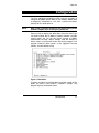
Set Trap Receivers
Use this screen to determine which IP managers receive traps
(messages) from your SNMP Solo. This screen permits you to
send traps about your UPS to four IP addresses (managers).
Also, you may determine the severity levels to assign to a
particular manager. To access the trap setting screen, type 3
from the Main Menu. The following screen displays:
16
Configuration
Tripp Lite
Figure 8 Trap Receivers
To set traps, at the prompt type:
Set, <space>, enter the number of the column from 1 through 4,
<space>, enter the IP address, <space>, severity code–1,2, or
3, and name of the community string. Press <enter>. The
severity level codes for messages are:
•
1
Informational
•
2
Warning
•
3
Severe
The trap receiver receives all assigned severity level messages
and the ones rated above. If you assign severity code 2, the
manager receives warning and severe levels.
A set trap example.
The top of the screen reflects your changes:
Configuration
17
SNMP Solo
To remove a trap receiver from the list, type clear, <space>,
and the desired list number at the prompt. Press <enter>.
The top of the screen reflects your changes:
To return to the Main Menu, type 0 at the prompt and press
<enter>.
Additional Setup Screen
To set your UPS address, type 4 and press Enter. This will
bring up the menu shown in Figure 9.
Figure 9 Additional Setup Screen
You need to set the UPS address. This address should match
the address you assigned to the UPS when you installed the
UPS. This address will determine which UPS the SNMP
adapter communicates with. You can set the address by typing
2 <0-127> and pressing Enter. Choose the number 0-127
that corresponds to the UPS address.
18
Configuration
Tripp Lite
After you have set the UPS address, you can return to the main
setup screen by typing 0 and pressing Enter.
NOTE:
The UPS address you set must correspond to the address
of the UPS you want the SNMP adapter to communicate
with.
Display Settings
This screen displays all of SNMP Solo’s current settings. To
access this screen, type 5 at the prompt from the Main Menu.
The current settings display:
Figure 10 Display All Current Settings
The settings are the following fields:
•
Local, SNMP Solo’s, Address and serial number (physical
address)
•
Gateway and Network address
•
System Contact Name (Your system administrator’s or a
contact’s name)
•
System Name
Configuration
19
SNMP Solo
•
Location (location of your UPS and SNMP Solo)
•
List of the current communities with their access control
code
•
List of the current trap receivers with their severity level
codes
Reset Configuration to Default
If you press <6>, the program resets all fields to default. To
display the results, press <5> for Display Settings. Most fields
have no values.
Figure 11 Reset Values To Default
To Save and Exit
If you are satisfied with your configurations, save them and exit.
To save, press <7>. The screen displays the following
message:
Figure 12 Save and Exit Messages For Configuration
20
Configuration
Tripp Lite
This messages informs or directs you:
1. The Setup program has ended.
2. Turn off the DIP switch (switch 1 UP).
3. Disconnect the power supply from the SNMP Solo.
4. Re-connect the power supply to the SNMP Solo.
TelNet Options
You can also TelNet to the IP address of the SNMP Solo after it
has been installed on your network. Once you have
successfully established a TelNet connection with the adapter
you may access the configuration menu as if you were directly
attached to it via the configuration port.
Figure 13 Telnet options
The TelNet options menu gives some additional features that
you can use after you have established a TelNet connection.
Configuration
21
SNMP Solo
Upload Firmware
CAUTION: The firmware upload has already been accomplished at the
factory. Before you proceed with this option, you must
contact our technical support team for assistance.
This option supports upgrades to the firmware program when
they become available. Should an upgrade be available, call our
technical support team for assistance with the upgrade.
If you inadvertently use this option, your system suspends
(locks). To restart, unplug the power supply from the SNMP
Solo, and re-connect the power supply to the SNMP Solo.
Exit Without Saving
This options lets you quit the program without saving any of
your configuration settings. To exit, type 0 (zero).
22
Configuration
Tripp Lite
Final Installation
Now that you have completed Configuration you are ready to
connect the SNMP Solo to your UPS and to the network. Follow
these steps to complete the installation:
1.
2.
3.
4.
5.
6.
7.
Turn DIP switch 1 on the SNMP Solo from the DOWN
(ON) position to the UP (OFF) position.
Disconnect the configuration cable from the SNMP Solo
adapter and the terminal or PC. Store this cable for
future use.
Disconnect the SNMP Solo from the power supply.
Locate the cable labled “73743”. This is the UPS
interface cable. Place the SNMP Solo close enough to
the UPS so the UPS interface cable can connect the
SNMP Solo’s serial port and the UPS’s serial port.
Connect the labelled end of the UPS interface cable to
the SNMP Solo’s serial port. Connect the other end to
the UPS’s serial port.
Connect the SNMP Solo to the Ethernet cable—either
UTP or BNC.
Reconnect the SNMP Solo to the power supply.
Verify the SNMP Solo Operation
After you complete all configuration settings and connect the
SNMP Solo to the network, check the LINK status.
LED Status After Power Up
At first, green and red LEDs do not light.
Green LED begins to pulse randomly, showing
network activity.
Five to ten seconds after power up, the red
LED flashes rapidly; this indicates that the
SNMP Solo is determining which UPS model is
connected to your system.
After SNMP Solo determines your UPS model,
the red LED turns off.
The red LED pulses once whenever the SNMP
Solo detects a communication failure.
Final Installation
23
SNMP Solo
If the SNMP Solo detects three communication
failures in a row, the red LED turns on and
stays on until the SNMP Solo receives a
successful communication from the UPS.
Establish Network Communications
1. PING SNMP Solo.
Issue a PING command from the NMS. If you do not get a
response, check the SNMP Solo’s network connection and
IP address.
2. Test the adapter with an NMS.
Perform a “get” command and a “set” command. If either
command fails, check the SNMP Solo access controls. The
manager must have read permission to execute a get
command successfully and read/write permission to
execute a set command successfully.
(See the Configuring the NMS section for a detailed
discussion.)
Your SNMP Solo SNMP adapter is now
installed and completely functional.
24
Final Installation
Tripp Lite
Configuring the NMS
To complete the SNMP Solo installation and configuration
process, you must compile the necessary MIBs to configure the
NMS.
Any NMS with a MIB compiler can manage the SNMP Solo
adapter. For instructions on how to compile MIBs for the most
popular NMSs—Novell’s NetWare Management Station,
Hewlett-Packard’s OpenView Network Node Manager, and
SunConnect’s SunNet Manager; see the corresponding heading
below.
General Network Management
Stations
Follow these general procedures to configure an NMS:
•
•
•
Compile the device MIBs.
Add SNMP Solo object to the Management Map.
Ping the SNMP Solo.
HP OpenView Network Node Manager for HPUX
Compile the Device MIB
8.
9.
10.
11.
12.
13.
Copy the UPS MIB file from the TAR formatted diskette
into the subdirectory /usr/OV/snmp_mibs.
From the main menu, select Options
Load/Unload MIBs: SNMP...
Select Load.
Select the MIB file copied earlier.
Select OK.
Add SNMP Solo Object to the Management Map
1.
2.
3.
Select the submap then Edit: Add Object.
Select the group computer.
With the middle (or opposite) mouse button, drag the
generic symbol subclass device to the submap.
Configuring the NMS
25
SNMP Solo
4.
5.
6.
7.
8.
9.
10.
Enter a name for the object in the Selection and Label
fields of the Add Object box.
Highlight IP Map from Object Attributes group.
Select Set Object Attributes button.
Enter Host name and IP address of SNMP Solo
adapter.
Enter OK.
Enter OK at Add Object menu.
Enter OK at Add Object:palette.
Poll the Device OIDs
1.
2.
From the main menu, select Monitor: MIB values then
Browse MIB: SNMP.
Move around the MIBs to view the UPS device
information.
Set the Device OIDs
From the main menu, select Monitor: MIB values then Browse
MIB: SNMP.
1.
2.
3.
Select a MIB variable you want to alter; click on it.
Enter the new value then click on Set.
Click on Start Query to view the changes.
Ping the SNMP Solo
1.
2.
Change active Window to Shell.
Type ping <IP address> and press <enter>.
Novell’s NetWare Management Station v.2.0
Compile the Device MIB
1.
Copy the UPS MIB file from the DOS formatted diskette
into the subdirectory
\nms\snmpmibs\current.
2.
From the main menu, select Tools then SNMP MIB
Compiler.
3.
From the SNMP MIB Compiler box, select Compile.
26
Configuring the NMS
Tripp Lite
Add SNMP Solo Object to the Management Map
The NMS will discover the NetMon and add it to the
Management map during its discovery pass.
Poll the Device OIDs
1.
2.
From the main menu, select Tools then the SNMP MIB
Browser.
From the SNMP MIB Browser box, select the IP
protocol and then enter the IP Address.
a)
select the profile to read.
b)
select OK.
Set the Device OIDs
1.
2.
3.
From the main menu, select Tools then SNMP MIB
Browser.
From the SNMP MIB Browser box, select Add.
From the SNMP Profile Editor box,
a)
assign the profile a name, a community, and a
poll interval.
b)
select the OID groups from the Group Choice
then select Add to transfer them to the Group
Selection(s).
c)
Save the profile.
Ping the SNMP Solo
1.
2.
From the main menu, first select Fault, second Test
Connectivity, and third Once.
From the Test Connectivity box,
a)
type in the IP address.
b)
select Test.
Configuring the NMS
27
SNMP Solo
SunConnect SunNet Manager
Compile the Device MIB
1. Copy the UPS MIB file from the TAR formatted diskette into
the subdirectory specified by na.snmp.schemas keyword
in $SNMHOME/snm.conf.
2. Execute mib2schema on the MIBs. This creates respective *.mib.oid and *.mib.schema and *.mib.traps
files.
3. In the SNM console window, select File|Load.
4. Select Management Database.
5. Click on *.mib schema, where *= the name of each MIB
copied in step 1 and select Load.
6. Start a new shell window; change to the subdirectory
$SNMHOME/agent and execute build_oid. This creates an
oid database using all compiled MIBs.
7. Append *.mib.traps to the file specified by na.snmptrap.default keyword in $SNMHOME/snm.conf.
Add SNMP Solo Object to the Management Map
1.
2.
3.
4.
5.
6.
7.
8.
9.
28
Enter the submap where the managed device will be
placed.
Select Edit, Create, Component, lanbox with the right
(opposite) mouse button. Select Create.
The Properties box displays.
Enter the SNMP Solo ’s name as it appears in
etc/hosts or in the name server.
Enter the SNMP WrCommunity.
Select the desired MIBs.
Choose a color for the device.
Select Apply. This adds the device to the submap.
Create a managed device view with the following steps:
a)
Select the relevant submap .
b)
Select Edit, Create, View, subnet with the right
(opposite) mouse button.
c)
Select Create and press <enter>.
d)
Enter the view name.
e)
Copy and paste the glyph into the managed
device view.
Configuring the NMS
Tripp Lite
Poll the Device OIDs
1.
2.
Select the device glyph with the right mouse button.
Select Quick Dum, *-MIB then one of the MIB groups.
A window appears displaying a snapshot of the group.
Set the device OIDs
1.
2.
3.
Select the device glyph with the right mouse button.
Select Set Request, *-MIB, {OID name}.
When the Set Tool application displays,
a)
Click on Get to receive the current values.
b)
Select a new value by clicking on New Value
then by clicking Set.
c)
Click on Get again to view the changes.
Ping the SNMP Solo
1.
2.
Change active Window to Shell.
Type ping <IP address> and press <enter>.
Configuring the NMS
29
SNMP Solo
Appendix
This appendix
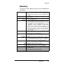
Troubleshooting.
has
three
sections:
Reference,
Glossary,
and
Reference
This section discusses Communities, IP Addresses, Sub net
masking, and routers/gateways.
Communities
A community is a string of printable ASCII characters that
identifies a user group with the same access privileges. For
example, a common community name is “public.”
For security purposes, the SNMP agent validates requests
before responding. The agent can be configured so that only
trap managers that are members of a community can send
requests and receive responses from a particular community.
This prevents unauthorized managers from viewing or changing
the configuration of a device.
IP Addresses
Every device on an internetwork must be assigned a unique IP
(Internet Protocol) address. An IP address is a 32-bit value
comprised of a network ID and a host ID. The network ID
identifies the logical network to which a particular device
belongs. The host ID identifies the particular device within the
logical network. IP addresses distinguish devices on an
internetwork from one another so that IP packets are properly
transmitted.
IP addresses appear in dotted decimal (rather than in binary)
notation. Dotted decimal notation divides the 32-bit value into
four 8-bit groups, or octets, and separates each octet with a
period. For example, 199.217.132.1 is an IP address in dotted
decimal notation.
To accommodate networks of different sizes, the IP address
has three divisions—Classes A for large, B for medium, and C
for small. The difference among the network classes is the
30
Appendix
Tripp Lite
number of octets reserved for the network ID and the number of
octets reserved for the host ID.
Class
A
B
C
Value of First Network ID
Host ID
Octet
1-126
first octet
last three octets
128-191
first two octets last two octets
192-223
first three
last octet
octets
Number of
Hosts
16,387,064
64,516
254
Any value between 0 and 255 is valid as a host ID octet except
for those values the InterNIC reserves for other purposes.
Value
0, 255
127
224-254
Purpose
Subnet masking
Loopback testing and interprocess communication
on local devices
IGMP multicast and other special protocols
Subnetting and Subnet Masks
Subnetting divides a network address into subnetwork
addresses to accommodate more than one physical network on
a logical network.
For example: A Class B company has 100 LANs (Local Area
Networks) with 100 to 200 nodes on each LAN. To classify the
nodes by its LANs on one main network, this company
segments the network address into 100 subnetwork addresses.
(If the Class B network address is 150.1.x.x, the address can be
segmented further from 150.1.1.x through 150.1.100.x.)
A subnet mask is a 32-bit value that distinguishes the network
ID from the host ID for different subnetworks on the same
logical network. Like IP addresses, subnet masks consist of four
octets in dotted decimal notation. You can use subnet masks to
route and filter the transmission of IP packets among your
subnetworks. The value “255” is assigned to octets that belong
to the network ID, and the value “0” is assigned to octets that
belong to the host ID.
For the example above, if you want all the devices on the
subnetworks to receive each other’s IP packets, set the subnet
mask to 255.255.0.0. If you want the devices on a single
subnetwork only to receive IP packets from other devices on its
Appendix
31
SNMP Solo
own subnetwork, set the subnet mask to 255.255.255.0 for the
devices on that subnetwork.
Subnet Mask
0.0.0.0
255.0.0.0
255.255.0.0
255.255.255.0
Routing and Filtering
IP packets are transmitted to all devices.
IP packets are only transmitted to
devices whose IP address’s first octet
matches the sender’s IP address’s first
octet.
IP packets are only transmitted to
devices whose IP address’s first two
octets match the sender’s IP address’s
first two octets.
IP packets are only transmitted to
devices whose IP address’s first three
octets match the sender’s IP address’s
first three octets.
Gateways
Gateway, also referred to as a router, is any computer with two
or more network adapters connecting to different physical
networks. Gateways allow for transmission of IP packets among
networks on an internetwork.
32
Appendix
Tripp Lite
Glossary
The Glossary section defines the terms used in the SNMP Solo
environment.
Agent
Dry Closure Input
Dry Closure Output
EtherNet
Gateway
IP
IP Address
MAC
MIB
NC
NIC
NMS
Implemented SNMP applications in network elements
(hosts). Agents perform the network management’s
functions as requested by the network administrator from
an NMS.
Non-powered contact type inputs—switch, relay contact,
open-collector.
Form C dry-contact outputs which are common, normally
open, or normally closed.
Local Area Network technology, originally developed by the
Xerox Corporation, can link up to 1,024 nodes in a bus
network. EtherNet provides raw data transfer in a rate of
10 megabits/sec. with actual throughputs in 2 to 3
megabits/sec. using a baseband (single-channel)
communication technique. EtherNet uses carrier sense
multiple access collision detection (CSMA/CD) that
prevents network failures when two devices attempt to
access the network at the same time. LAN hardware
manufactures use EtherNet protocol; their products may
not be compatible.
A computer that attaches to a number of networks and
routes packets between them. The packets can be
different protocols at the higher levels.
Internet Protocol—The TCP/IP standard protocol defines
the IP datagram as the unit of information passed across
a network.
Internet Protocol Address—A 32-bit address assigned to
hosts participating in a TCP/IP network. The IP address
consists of network and host portions. It is assigned to
an interconnection of a host to a physical network.
Medium Access Control—The network layer between the
physical and the datalink layers. Specifically, the physical
(hardware) address exists in this layer.
Management Information Base—The database, i.e., set of
variables maintained by a gateway running SNMP.
Normally Closed —Refers to a contact switch that is
normally closed.
Network Interface Controller—The hardware interface to
the physical connection to the network.
Network Management Station
Appendix
33
SNMP Solo
NO
OID
Personality
Router
RS-232
SNMP
Sub-Agent
TCP/IP
TES
TFTP Server
UDP/IP
UPS
34
Appendix
Normally Open—Refers to a contact switch that is normally
open.
Object Identifier—The variables defined in a MIB.
The current device specific software uploaded to the SNMP
Solo.
A computer that manages traffic between different network
segments or different network topologies. It directs the
destination IP address. The network media can be
different, but the higher level protocols must be the
same.
A specification for serial communication between data
communication equipment and computers.
Simple Network Management Protocol—A standard
protocol used to monitor IP hosts, networks, and
gateways. SNMP defines a set of simple operations that
can be performed on the OIDs of the MIBs managed by
the monitored Agents. It employs the UDP/IP transport
layer to move its object between the Agents and the
NMS.
A software module that manages specific MIB sub-groups
for an Agent. They communicate with the Agent using a
SMUX (multiplexer).
Transmission
Control
Protocol/Internet
Protocol—A
protocol suite used by more than 15 million users with a
UNIX association and widely used to link computers of
different kinds.
Terminal Emulation Software—Communications program to
transform a personal computer into a terminal for the
purpose of data communications.
Trivial File Transfer Protocol Server—A host to provide
services according to TFTP; a TCP/IP standard protocol
for file transfer with minimal capability and overhead
depending on UDP for its datagram delivery service.
User Datagram Protocol/Internet Protocol—A TCP/IP
standard protocol. It enables transfer of information
between applications running on different host. It is
referred to as an unreliable, connectionless datagram
delivery service.
Uninterruptible Power Supply—A device that supplies
power to your system with rechargeable batteries if there
is an AC power failure.
Tripp Lite
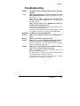
Troubleshooting
Problem:
The TES (Terminal Emulation Software) does not display
anything.
Solution:
Make sure the Dip switch is set correctly. Switch 1 is ON
when DOWN and Switch 2 is UP. This applies only when
you power up.
Make sure the TES’s communication parameters are
correct. They should be 9600 baud rate, no parity, 8-data
bits, and 1 stop bit.
Make sure the ends of the SM-SER-117A cable are
plugged into their respective ports.
PROBLEM:
The ends of the cable indicate which belongs to the CPU and
which belongs to the SNMP Solo.
The end of the hooded cable nearest the label belongs to the
CPU, and the end farthest away belongs to the SNMP Solo.
The NMS cannot ping the SNMP Solo.
Solution:
Make sure the network connection to the SNMP Solo is
good.
Solution:
Make sure the cable is in good condition.
Solution:
Make sure to set the Community String [Set Access
Controls, Type 2, Set 1 through 4]. Follow these steps:
Solution
Name the community with any lowercase name. (A UPS
monitors a designated community.)
Make sure to set the Manager Table. Set Access Controls,
Type 3, Set 1 through 4]. Follow these steps:
Define the Manager IP Address, Community string, and
Access Permission together.
The trap manager’s community should be the same number
as the number of the community it monitors.
The trap manager’s status is set to Accept YES to enable
sending traps or to Accept to No to disable.
Appendix
35
SNMP Solo
Placing a Technical Support Call
In order to diagnose the problem you are having, our technicians need
the following information from you:
Installation Site:
Company Name:
Address:
City:
State:
ZIP code:
Installation Site Contact:
Full Name:
Phone Number:
Fax Number:
If you are a consultant,
Consultant Name:
Phone Number:
Fax Number:
Computer System:
Operating System and version:
System Manufacturer:
System Model Number:
NMS name and revision number:
UPS:
Manufacturer:
Model Name/Number:
Type of Port Connector (How many pins, male or female.):
What are the symptoms?
36
Appendix
Tripp Lite
" Technical Support "
If you have any questions about your SNMP Solo or
about any Tripp Lite product, you can contact us at:
(773) 869-1234
Appendix
37
SNMP Solo
Reference Worksheet
Local Address: ___.___.___.___
Gateway Address: ___.___.___.___
Network ID: ___.___.___.___
System’s Contact Name:
System’s Name:
System’s Location:
Serial No:
__:__:__:__:__:__
Current access controls of SNMP communities:
Manager IP Address
Community String
Access Permission
Current trap receivers:
Receiver IP Address
38
Severity
Reference Worksheet
Community
Accept