1
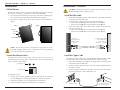
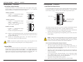
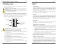
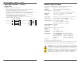
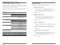
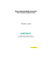
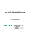
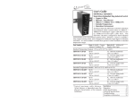
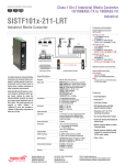
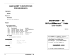
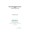
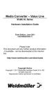
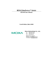
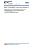
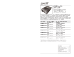
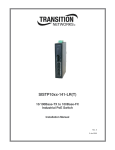
User’s Guide
SISTF10xx-140-LR(T)
SISTF10xx-160-LR(T)
SISTF10xx-170-LR(T)
Stand-Alone Ethernet Switch
• 10Base-T / 100Base-TX to 100Base-FX
• Extended Temperature
• Hazardous Environment
SISTF10xx-140-LR(T)
Transition Networks industrial Ethernet switch
connects 10Base-T / 100Base-TX twisted-pair
copper cable to 100Base-FX fiber-optic cable. It is
designed for harsh industrial environments and is
also available in models that operate in either
standard or extended temperature ranges.
The SISTF10xx-140-LR(T) model includes four (4) copper RJ-45 ports and one (1)
duplex fiber-optic port.
Part Number
Ports 1 - 4: Copper
10Base-T/100Base-TX
Port 5: Duplex Fiber-Optic
100Base-FX Duplex
Standard Temperature Models: 0°C to 60°C (32°F to 140°F):
SISTF1011-140-LR
SISTF1012-140-LR
SISTF1013-140-LR
SISTF1014-140-LR
RJ-45
100 m (328 ft)*
RJ-45
100 m (328 ft)*
RJ-45
100 m (328 ft)*
RJ-45
100 m (328 ft)*
ST, 1300 nm multimode
2 km (1.2 miles)*
ST, 1310 nm single mode
15 km (9.3 miles)*
SC, 1300 nm multimode
2 km (1.2 miles)*
SC, 1310 nm single mode
15 km (9.3 miles)*
Extended Temperature Models: -40°C to 75°C (-40°F to 167°F):
SISTF1011-140-LRT
RJ-45
ST, 1300 nm multimode
100 m (328 ft)*
2 km (1.2 miles)*
SISTF1012-140-LRT
RJ-45
ST, 1310 nm single mode
100 m (328 ft)*
15 km (9.3 miles)*
SISTF1013-140-LRT
RJ-45
SC, 1300 nm multimode
100 m (328 ft)*
2 km (1.2 miles)*
SISTF1014-140-LRT
RJ-45
SC, 1310 nm single mode
100 m (328 ft)*
15 km (9.3 miles)*
* Typical maximum cable distance.
Actual distance is dependent upon the
physical characteristics of the network
installation.
Installation . . . . . . . . . . . . . . . . . .4
Operation . . . . . . . . . . . . . . . . . . .5
Cable Specifications . . . . . . . . . .12
Technical Specifications . . . . . . .15
Troubleshooting . . . . . . . . . . . . .17
Compliance Information . . . . . . .20
SISTF10xx-140-LR(T) / -160-LR(T) / -170-LR(T)
SISTF10xx-160-LR(T)
SISTF10xx-170-LR(T)
The SISTF10xx-160-LR(T) model includes six (6) copper RJ-45 ports and two (2)
duplex fiber-optic ports.
The SISTF10xx-170-LR(T) model includes seven (7) copper RJ-45 ports and one (1)
duplex fiber-optic port.
Part Number
Part Number
Ports 1 - 6: Copper
10Base-T/100Base-TX
Ports 7 & 8: Duplex Fiber-Optic
100Base-FX Duplex
Ports 1 - 7: Copper
10Base-T/100Base-TX
Port 8: Duplex Fiber-Optic
100Base-FX Duplex
Standard Temperature Models: 0°C to 60°C (32°F to 140°F):
Standard Temperature Models: 0°C to 60°C (32°F to 140°F):
SISTF1011-160-LR
SISTF1011-170-LR
SISTF1012-160-LR
SISTF1013-160-LR
SISTF1014-160-LR
RJ-45
100 m (328 ft)*
RJ-45
100 m (328 ft)*
RJ-45
100 m (328 ft)*
RJ-45
100 m (328 ft)*
ST, 1300 nm multimode
2 km (1.2 miles)*
ST, 1310 nm single mode
15 km (9.3 miles)*
SC, 1300 nm multimode
2 km (1.2 miles)*
SC, 1310 nm single mode
15 km (9.3 miles)*
SISTF1012-170-LR
SISTF1013-170-LR
SISTF1014-170-LR
RJ-45
100 m (328 ft)*
RJ-45
100 m (328 ft)*
RJ-45
100 m (328 ft)*
RJ-45
100 m (328 ft)*
ST, 1300 nm multimode
2 km (1.2 miles)*
ST, 1310 nm single mode
15 km (9.3 miles)*
SC, 1300 nm multimode
2 km (1.2 miles)*
SC, 1310 nm single mode
15 km (9.3 miles)*
Extended Temperature Models: -40°C to 75°C (-40°F to 167°F):
SISTF1011-160-LRT
RJ-45
ST, 1300 nm multimode
100 m (328 ft)*
2 km (1.2 miles)*
SISTF1012-160-LRT
RJ-45
ST, 1310 nm single mode
100 m (328 ft)*
15 km (9.3 miles)*
SISTF1013-160-LRT
RJ-45
SC, 1300 nm multimode
100 m (328 ft)*
2 km (1.2 miles)*
SISTF1014-160-LRT
RJ-45
SC, 1310 nm single mode
100 m (328 ft)*
15 km (9.3 miles)*
Extended Temperature Models: -40°C to 75°C (-40°F to 167°F):
SISTF1011-170-LRT
RJ-45
ST, 1300 nm multimode
100 m (328 ft)*
2 km (1.2 miles)*
SISTF1012-170-LRT
RJ-45
ST, 1310 nm single mode
100 m (328 ft)*
15 km (9.3 miles)*
SISTF1013-170-LRT
RJ-45
SC, 1300 nm multimode
100 m (328 ft)*
2 km (1.2 miles)*
SISTF1014-170-LRT
RJ-45
SC, 1310 nm single mode
100 m (328 ft)*
15 km (9.3 miles)*
* Typical maximum cable distance. Actual distance is dependent upon the
physical characteristics of the network installation.
* Typical maximum cable distance. Actual distance is dependent upon the
physical characteristics of the network installation.
2
24-hour Technical Support: 1-800-260-1312 -- International: 00-1-952-941-7600
[email protected] -- Click the “Transition Now” link for a live Web chat.
3
SISTF10xx-140-LR(T) / -160-LR(T) / -170-LR(T)
Installation
Installation -- Continued
DIN-Rail Mount
The Ethernet switch includes an aluminum DIN-Rail mounting plate attached
to the device’s back panel. To mount the device onto a DIN-Rail:
1.
2.
Insert the top of the DIN-Rail into the upper slot of the mounting plate.
The stiff metal spring should be positioned behind the DIN-Rail.
Push down and rotate the device to snap it into place on the DIN-Rail as
shown.
Step 2:
Step 1:
CAUTION: Disconnect the Ethernet switch from the DC power source
BEFORE installing and/or wiring the device.
Install the Fiber Cable
1.
Locate or build 100Base-FX fiber cable with male, two-stranded TX to RX
connectors installed at both ends.
2.
Connect the fiber cables to the Ethernet switch as described:
• Connect the male TX cable connector to the female TX port.
• Connect the male RX cable connector to the female RX port.
3.
Connect the fiber cables to the other device (another media converter,
hub, etc.) as described:
• Connect the male TX cable connector to the female RX port.
• Connect the male RX cable connector to the female TX port.
mounting
plate
spring
DIN-Rail
Connect the
fiber cable to the
Ethernet switch
as shown.
NOTE: The Ethernet switch is intended to be grounded to a wellgrounded mounting surface such as a metal plate. Install the grounding
wire prior to connecting any other device.
Ground the Ethernet Switch
Grounding the Ethernet switch helps limit the effects of noise due to
electromagnetic interference (EMI). The grounding screw is located on the top
panel next to the terminal block.
RX
RX
TX
TX
Install the Copper Cable
The AutoCross feature allows either straight-through (MDI) or crossover (MDIX) copper cable to be used when connecting devices via the RJ-45 port.
1.
Locate or build 10Base-T or 100Base-TX copper cables with male, RJ-45
connectors installed at both ends.
2.
Connect the RJ-45 connector at one end of the cable to the RJ-45 port on
the Ethernet switch.
3.
Connect the RJ-45 connector at the other end of the cable to the RJ-45
port on the other device (PLC, workstation, etc.).
grounding screw
terminal block
Connect the fiber cable
to the other device
(media converter,
switch, etc.) as shown
To ground the device:
4
1.
Connect one end of the grounding wire (not included) to the grounding
screw by looping one end of the grounding wire under the star washer.
2.
Tighten the grounding screw with a phillips-head screwdriver.
3.
Connect the other end of the grounding wire to earth ground.
24-hour Technical Support: 1-800-260-1312 -- International: 00-1-952-941-7600
RJ-45 ports on the
Ethernet switch
RJ-45 port
on the other device
(PLC, work station, etc.)
[email protected] -- Click the “Transition Now” link for a live Web chat.
5
SISTF10xx-140-LR(T) / -160-LR(T) / -170-LR(T)
Installation -- Continued
Installation -- Continued
Set the Port Alarm Switches
Install the Port Alarm Device
The port alarm feature is used to determine faults at the copper or fiber ports.
The dip switches are located on the top panel of the device. Use a small flat
blade screwdriver or a similar device to set the switches.
SISTF10xx-140-LR(T)
6-contact terminal block
V2+
PORT
ALARM
fault contacts
FAULT
SISTF10xx-160-LR(T)
SISTF10xx-170-LR(T)
OFF
V1+
PORT
ALARM
V1-
The contacts for the fault alarm are on the 6-contact terminal block, located
on the top panel of the Ethernet switch. To install a port alarm device:
1.
Insert the two wires from the user-supplied port alarm device into the two
terminals marked “FAULT” on the 6-contact terminal block.
2.
Secure the wire by tightening the corresponding screw on the side of the
terminal block.
ON
on = Enables the corresponding port alarm. If the link for that port fails (or if
a power supply input fails), the internal relay forms an open circuit and
the FAULT LED lights up.
off = Disables the corresponding port alarm. The internal relay forms a
closed circuit and the FAULT LED remains off.
NOTE: To activate the updated switch setting, cycle the power to the
Ethernet switch by turning off the power, then turning it back on.
Internal Relay
The internal relay that activates the alarm feature is connected to the two
middle contacts on the 6-contact terminal block. A user-supplied fault alarm
device can be connected to these fault contacts. An example would be to
connect the fault circuit to a warning light located in the control room. The
light can be set up to turn on when a fault is detected. (See page 7.)
6
PWR1
The screws to secure
the wires are located
on the side of the
terminal block.
V1, V2 INPUTS
12-48 VDC
DIP
P1
P2
P3
P4
P5
P6
P7
P8
PWR2
V2-
ON
ON
• Switches 1 - 7 correspond to copper
ports 1 - 7, respectively.
• Switch 8 corresponds to fiber port 8.
DIP
SISTF10xx-170-LR(T)
OFF
1 2 3 4 5 6 7 8
• Switches 1 - 6 correspond to copper
ports 1 - 6, respectively.
• Switches 7 and 8 correspond to fiber
ports 7 and 8, respectively.
P1
P2
P3
P4
P5
ON
SISTF10xx-160-LR(T)
SISTF10xx-140-LR(T)
1 2 3 4 5
• Switches 1 - 4 correspond to copper
ports 1 - 4, respectively.
• Switch 5 corresponds to fiber port 5.
A user-supplied port alarm device can be connected to the Ethernet switch to
alert the user whenever a power fault or a port fault occurs. At least one port
alarm switch (see page 6) must be “ON” to enable the port alarm feature.
24-hour Technical Support: 1-800-260-1312 -- International: 00-1-952-941-7600
NOTE: Calculate the maximum possible current in each power wire and
signal wire. Observe all electrical codes for maximum current allowed.
If the current goes above the maximum ratings, the wiring would
overheat, causing serious damage to the network equipment.
Please note the following when wiring the network:
• Signal lines must not be directly connected to outdoor wiring.
•
Use separate paths to route the power wiring and the signal wiring. If
power wiring and signal wiring paths must cross, make sure the wires are
perpendicular at the intersection point.
•
Do not run signal wiring and power wiring in the same wire conduit. To
avoid interference, wires with different signal characteristics should also
be routed separately.
•
Use the type of signal transmitted through a wire to determine which
wires should be kept separate. The rule of thumb is that wiring with
similar electrical characteristics can be bundled together.
•
Keep input wiring and output wiring separate.
•
Where necessary, label the wiring to all devices in the network.
[email protected] -- Click the “Transition Now” link for a live Web chat.
7
SISTF10xx-140-LR(T) / -160-LR(T) / -170-LR(T)
Installation -- Continued
Operation
Power the Ethernet switch
Features
This device is suitable for use in Class I, Division 2, Groups A, B, C and D or
non-hazardous locations only.
WARNING: EXPLOSION HAZARD - Do not disconnect equipment
unless power has been removed or the area is known to be nonhazardous.
WARNING: EXPLOSION HAZARD - Substitution of components may
impair suitability for Class I, Division 2.
The Ethernet switch is designed for both a primary and a backup power
supply via the 6-contact terminal block, located on the top panel of the
device. Both power inputs can be connected simultaneously to live DC
power sources. If one power source fails, the other live source acts as a
backup, and automatically supplies the Ethernet switch with power.
6-contact terminal block
backup power
contacts
primary power
contacts
With the Auto-Negotiation feature, the Ethernet switch automatically
configures itself to achieve the best possible mode of operation over the
copper link. The device broadcasts its speed (10 Mb/s or 100 Mb/s) and
duplex capabilities (either full- or half-duplex) and negotiates the best mode of
operation between the two linked devices.
If the device is connected to a non-negotiating device over the copper link, it
will default to 10 Mb/s speed, half-duplex mode.
AutoCross
The AutoCross feature allows either straight-through (MDI) or crossover (MDIX) cables to be used when connecting the Ethernet switch to devices such as
PLCs or workstations. AutoCross determines the characteristics of the cable
connection and automatically configures the unit to link up, regardless of the
cable configuration. (Requires no operator intervention.)
V2+
V2-
V1+
PWR2
Plug-and-Play
FAULT
The Ethernet switch models are plug-and-play devices, so that software
configuration is not required at installation or during maintenance.
PWR1
The screws to secure
the wire are located
on the side of the
terminal block.
V1V1, V2 INPUTS
12-48 VDC
CAUTION: Before connecting the Ethernet switch to the 12-48 VDC
power source, ensure the power source voltage is stable.
To provide PRIMARY (PWR1) power to the Ethernet switch:
8
Auto-Negotiation
1.
Insert the positive (+) DC wire from the 12-48VDC power source into the
terminal marked “V1+”.
2.
Insert the negative (-) DC wire into the terminal marked “V1-”.
3.
Secure the wires by tightening the corresponding screws on the side of
the terminal block.
Switching, Filtering, and Forwarding
Packets are either filtered or forwarded when they arrive at one of the
switched ports.
• Packets with source and destination addresses belonging to the same port
segment are filtered and constrained to one port (relieving the rest of the
network from the need to process them).
• Packets with a destination address to another port segment are forwarded
to the appropriate port, and are not sent to the other ports where it is not
needed.
• Packets that are used in maintaining the operation of the network (such as
the occasional multi-cast packet) are forwarded to all ports.
The Ethernet switch operates in the store-and-forward switching mode, which
eliminates bad packets and enables peak performance to be achieved when
there is heavy traffic on the network.
To provide BACKUP (PWR2) power to the Ethernet switch:
Switching and Address Learning
1.
Insert the positive (+) DC wire from the 12-48VDC power source into the
terminal marked “V2+”.
2.
Insert the negative (-) DC wire into the terminal marked “V2-”.
3.
Secure the wires by tightening the corresponding screws on the side of
the terminal block.
The Ethernet switch address table holds up to 1K node addresses, making it
suitable for use with large networks. The address tables are self-learning, so
that as nodes are added, removed, or moved from one segment to another, the
Ethernet switch automatically keeps up with new node locations. An addressaging algorithm deletes the least-used addresses in favor of newer, more
frequently used addresses. To reset the address buffer, power down the unit
and then power it back up.
24-hour Technical Support: 1-800-260-1312 -- International: 00-1-952-941-7600
[email protected] -- Click the “Transition Now” link for a live Web chat.
9
SISTF10xx-140-LR(T) / -160-LR(T) / -170-LR(T)
Operation -- Continued
Operation -- Continued
Status LEDs
Use the status LEDs to monitor the Ethernet switch operation in the network.
(amber)
on = Primary power is connected to device.
PWR2
(amber)
on = Backup power is connected to the device.
PWR 1
PWR 2
FAULT
FAULT (red)
on = If any of the five (5) port alarm switches are “on“
and the link on the corresponding port is inactive (ex:
switch 3 is “on” and port 3 is inactive); or there is a loss
of either the primary power or backup power.
100BASE-FX
TX
The “100M” LEDs indicate the link status of the corresponding fiber port
(100Base-FX):
(green)
SISTF10xx-170-LR(T)
100BASE-FX
100BASE-FX
TX
PWR 1
PWR 2
8
FAULT
RX
100M
RX
TX
PWR 1
PWR 2
8
FAULT
RX
100M
TX
7
7
Fiber Port LEDs
100M
Industrial Switch
PWR1
SISTF10xx-160-LR(T)
Industrial Switch
SISTF10xx-140-LR(T)
The three LEDs near the top indicate the power and fault status:
Industrial Switch
Power and Fault LEDs
RX
100M
10/100BASE-TX
100M
on = Fiber link is active.
5
flashing = Data is being transmitted over the fiber link.
6
5
6
10/100BASE-TX
Copper Port LEDs
The LEDs embedded in each of the RJ-45 port indicate the status of the
corresponding copper link (10/100Base-T/TX):
10M
(green)
on = Copper link is active at 10 Mb/s.
flashing = Data is being transmitted over the copper link
at 10 Mb/s.
100M
(green)
on = Copper link is active at 100 Mb/s.
flashing = Data is being transmitted over the copper link
at 100 Mb/s.
10
24-hour Technical Support: 1-800-260-1312 -- International: 00-1-952-941-7600
[email protected] -- Click the “Transition Now” link for a live Web chat.
11
SISTF10xx-140-LR(T) / -160-LR(T) / -170-LR(T)
Cable Specifications
Cable Specifications -- Continued
The physical characteristics must meet or exceed IEEE 802.3™ specifications.
Fiber Cable
Extended Temperature Models
SISTF1011-140-LRT
SISTF1011-160-LRT
SISTF1011-170-LRT
Fiber Optic Transmitter Power:
Fiber Optic Receiver Sensitivity:
Link Budget:
1300 nm multimode
min: -20.0 dBm max: -14.0 dBm
min: -36.0 dBm max: -32.0 dBm
16.0 dB
1300 nm multimode
min: -20.0 dBm max: -14.0 dBm
min: -36.0 dBm max: -32.0 dBm
16.0 dB
SISTF1012-140-LRT
SISTF1012-160-LRT
SISTF1012-170-LRT
Fiber Optic Transmitter Power:
Fiber Optic Receiver Sensitivity:
Link Budget:
1310 nm single mode
min: -15.0 dBm max: -6.0 dBm
min: -34.0 dBm max: -32.0 dBm
19.0 dB
1310 nm single mode
min: -15.0 dBm max: -6.0 dBm
min: -34.0 dBm max: -32.0 dBm
19.0 dB
SISTF1013-140-LRT
SISTF1013-160-LRT
SISTF1013-170-LRT
Fiber Optic Transmitter Power:
Fiber Optic Receiver Sensitivity:
Link Budget:
1300 nm multimode
min: -20.0 dBm max: -14.0 dBm
min: -36.0 dBm max: -32.0 dBm
16.0 dB
SISTF1013-140-LR
SISTF1013-160-LR
SISTF1013-170-LR
Fiber Optic Transmitter Power:
Fiber Optic Receiver Sensitivity:
Link Budget:
1300 nm multimode
min: -20.0 dBm max: -14.0 dBm
min: -36.0 dBm max: -32.0 dBm
16.0 dB
SISTF1014-140-LRT
SISTF1014-160-LRT
SISTF1014-170-LRT
Fiber Optic Transmitter Power:
Fiber Optic Receiver Sensitivity:
Link Budget:
1310 nm single mode
min: -15.0 dBm max: -6.0 dBm
min: -34.0 dBm max: -32.0 dBm
19.0 dB
SISTF1014-140-LR
SISTF1014-160-LR
SISTF1014-170-LR
Fiber Optic Transmitter Power:
Fiber Optic Receiver Sensitivity:
Link Budget:
1310 nm single mode
min: -15.0 dBm max: -6.0 dBm
min: -34.0 dBm max: -32.0 dBm
19.0 dB
Bit Error Rate:
Single mode fiber (recommended):
Multimode fiber (recommended):
Multimode fiber (optional):
<10-9
9 µm
62.5/125 µm
100/140, 85/140, 50/125 µm
Standard Models
SISTF1011-140-LR
SISTF1011-160-LR
SISTF1011-170-LR
Fiber Optic Transmitter Power:
Fiber Optic Receiver Sensitivity:
Link Budget:
SISTF1012-140-LR
SISTF1012-160-LR
SISTF1012-170-LR
Fiber Optic Transmitter Power:
Fiber Optic Receiver Sensitivity:
Link Budget:
This device is certified by the manufacturer to comply with DHHS Rule
21/CFR, Subchapter J applicable at the date of manufacture.
The fiber optic transmitters on this device meet Class I Laser safety
requirements per IEC-825/CDRH standards and comply with 21
CFR1040.10 and 21CFR1040.11.
CAUTION: Visible and invisible laser radiation when open. Do not
stare into beam or view directly with optical instruments.
CAUTION: Use of controls, adjustments or the performance of
procedures other than those specified herein may result in hazardous
radiation exposure.
12
24-hour Technical Support: 1-800-260-1312 -- International: 00-1-952-941-7600
[email protected] -- Click the “Transition Now” link for a live Web chat.
13
SISTF10xx-140-LR(T) / -160-LR(T) / -170-LR(T)
Cable Specifications -- Continued
Technical Specifications
Copper Cable
For use with Transition Networks Model Ethernet switch or equivalent
Category 5: (minimum requirement)
Gauge / Attenuation: 24 to 22 AWG / 22.0 dB per 100m @ 100 MHz
Standards:
IEEE 802.3™, 802.3u™; 802.3x™
Data Rate:
10 Mb/s, 100 Mb/s (copper); 100 Mb/s (fiber)
• Straight-through OR crossover cable may be used.
• Shielded twisted-pair (STP) OR unshielded twisted-pair (UTP) may be used
• Pins 1&2 and 3&6 are the two active pairs in an Ethernet network .
• RJ-45 Pin-out: Pin 1 = TD+, Pin 2 = TD-, Pin 3 = RD+, Pin 6 = RD• Use only dedicated wire pairs for the active pins:
(e.g., blue/white & white/blue, orange/white & white/orange, etc.)
• Do not use flat or silver satin wire.
Processing Type:
Store and Forward
w/ IEEE802.3x™ full-duplex, non-blocking flow control
Dimensions:
1.8" x 5.3" x 4.1" (46 mm x 135 mm x 105 mm)
Weight:
1.4 lb. (0.63 kg) (approximate)
Input Voltage:
12-48VDC, 0.2-0.7A, 2.4W (minimum), (redundant inputs)
Input Current:
0.25 A @ 24 VDC (SISTF10xx-140-LR(T))
0.35 A @ 24 VDC (SISTF10xx-160-LR(T) / -170-LR(T))
Overload Current:
1.1 A (SISTF10xx-140-LR(T))
1.6 A (SISTF10xx-160-LR(T) / -170-LR(T))
reverse polarity protection on all models
Straight-Through Cable
Crossover Cable
Twisted Pair #1
1
2
1
2
Twisted Pair #1
1
2
1
2
Twisted Pair #2
3
6
3
6
Twisted Pair #2
3
6
3
6
Forward & Filtering: 148810 pps
Packet Buffer:
256 KB
Address Table Size: 1000 Unicast MAC addresses
Latency:
< 5 µs
Alarm Relay:
1.0 A @ 24 VDC
Mechanical:
Ingress Protection: IP30
Environment:
Tmra* (standard temp): 0 to 60°C (32 to 140°F)
Tmra* (extended temp): -40 to 75°C (-40 to 167°F)
Warranty:
Storage Temperature:
-40 to 85°C (-40 to 185°F)
Humidity:
5 to 95%, non condensing
Lifetime
*Manufacturer’s rated ambient temperature.
The information contained in this user’s guide is subject to change. For the most
up-to-date information see the user’s guide on line at: www.transition.com.
CAUTION: This device is intended to be supplied by a listed power unit
marked LPS or Limited Power Source, provided with a connector for field
wiring terminal, and output rated 12-48VDC, 0.2-0.7 A, 24 W minimum.
CAUTION: This device is designed for operation with a safety extra-low
voltage (SELV) in compliance with IEC950 / EN60950 / VDE0805 and in
compliance with the low voltage directive 73/23/EEC and 93/68/EEC.
14
24-hour Technical Support: 1-800-260-1312 -- International: 00-1-952-941-7600
[email protected] -- Click the “Transition Now” link for a live Web chat.
15
SISTF10xx-140-LR(T) / -160-LR(T) / -170-LR(T)
Technical Specification -- Continued
Troubleshooting
This device has been evaluated as EEx nC IIC T4 equipment under DEMKO
Certificate No. 03 ATEX 0324537U. Each module is suitable for use in Zone 2
Explosive Atmospheres. The device must be installed in a minimum IP 54
enclosure as defined in IEC 60529 and EN 60529.
If the device fails, isolate and correct the fault by determining the answers to the
following questions and then taking the indicated action:
1.
This device is a building-in type. The installation into a certain end equipment
shall comply with fire enclosure request of IEC 60950/EN60950 or similar
sentence.
•
•
•
EMS Type Tests
Test
Is the PWR1 LED illuminated?
NO
YES
Description
IEC61000-4-2 ESD
IEC61000-4-3 Radiated RFI
IEC61000-4-4 Burst
(Fast Transient)
IEC61000-4-5 Surge
Test Levels
Air discharge
Contact discharge
ESD contact discharge
Housing
Power supply lines
Communication lines
Relay
Power supply lines
Relay
IEC61000-4-6 Induced
Power supply lines
(Conducted RFI)
Communication lines
Relay
Severity
+/- 8 KV
+/- 6 KV
+/- 6 KV
10V/m, 80 MHz - 1 GHz
AM 1 KHz, 80% mod
10 V/m, 0.9 - 1.8 GHz
FM 200 Hz 50% square
+/- 2 KV
+/- 1 KV
+/- 1 KV
+/- 2 KV, 12 Ω, CM
+/- 1 KV, 2 Ω, DM
+/- 2 KV, 12 Ω, CM
+/- 1 KV, 2 Ω, DM
10 Vrms, 150-80 MHz
AM 1 KHz, 80% mod
10 Vrms, 150-80 MHz
AM 1 KHz, 80% mod
10 Vrms, 150-80 MHz
AM 1 KHz, 80% mod
3
3
3
3
•
2.
•
•
Description
Test Levels
IEC 60068-2-6
IEC 60068-2-27
IEC 60068-2-32
Vibration
Shock
Free fall
10 - 500 - 10 Hz, 0.5 oct./min, 4g, X, Y, Z (3 axes)
50 g, 11 ms, +/-X, +/-Y, +/- Z (6 direction)
75 cm, 1 corner, 3 edges, 6 faces (total 10 drops)
•
3.
3
•
•
•
3
Proceed to step 3.
Is the FAULT LED illuminated?
YES
3
If one or more port alarm switches (1 - 5) is ON, the device lost the
corresponding fiber or copper link, or the primary power or backup
power.
Ensure the problem copper or fiber link is properly connected.
Contact Tech Support: 800-260-1312, Int’l: 00-1-952-941-7600.
NO
3
•
Proceed to step 4.
Is a 100M LED (near a fiber link) illuminated?
NO
•
•
•
Check the corresponding fiber cables for proper connection.
Verify that the TX and RX cables on the device are connected to the
RX and TX ports, respectively, on the other device.
Contact Tech Support: 800-260-1312, Int’l: 00-1-952-941-7600.
YES
•
24-hour Technical Support: 1-800-260-1312 -- International: 00-1-952-941-7600
Ensure the power source is the proper voltage (12 - 48 VDC).
Ensure the (+) and (-) wires from the power source are inserted
properly in the terminal block contacts labeled “PWR2”.
Contact Tech Support: 800-260-1312, Int’l: 00-1-952-941-7600.
YES
4.
Test
Proceed to step 2.
Is the PWR2 LED illuminated?
NO
•
3
3
3
3
Environmental Type Tests
16
Ensure the power source is the proper voltage (12 - 48 VDC).
Ensure the (+) and (-) wires from the power source are inserted
properly in the terminal block contacts labeled “PWR1”.
Contact Tech Support: 800-260-1312, Int’l: 00-1-952-941-7600.
Proceed to step 5.
[email protected] -- Click the “Transition Now” link for a live Web chat.
17
SISTF10xx-140-LR(T) / -160-LR(T) / -170-LR(T)
Troubleshooting -- Continued
5.
Is a 100M LED (near the fiber links) flashing?
NO
•
If there is activity on the corresponding fiber port, disconnect and
reconnect the fiber cable to restart the initialization process.
If there is no activity on the corresponding fiber port, contact Tech
Support: 800-260-1312, Int’l: 00-1-952-941-7600.
•
YES
•
6.
Proceed to step 6.
Are any of the 10M LEDs (on the RJ-45 port) illuminated?
YES
•
•
The device has selected 10 Mb/s for the twisted-pair link.
If the speed is not correct, disconnect and reconnect the twisted-pair
cable to restart the initialization process.
Proceed to step 7.
•
NO
•
7.
Proceed to step 7.
Are any of the 100M LEDs (on the RJ-45 port) illuminated?
YES
•
•
The device has selected 100 Mb/s for the twisted-pair link.
If the speed is not correct, disconnect and reconnect the twisted-pair
cable to restart the initialization process.
Contact Tech Support: 800-260-1312, Int’l: 00-1-952-941-7600.
•
NO
•
•
Check the twisted-pair cables for proper connection.
Contact Tech Support: 800-260-1312, Int’l: 00-1-952-941-7600.
Contact Us
Technical Support
Technical support is available 24 hours a day
US and Canada:
1-800-260-1312
International:
00-1-952-941-7600
Transition Now
Chat live via the Web with Transition Networks Technical Support.
Log onto www.transition.com and click the Transition Now link.
Web-Based Seminars
Transition Networks provides seminars via live web-based training.
Log onto www.transition.com and click the Learning Center link.
E-Mail
Ask a question anytime by sending an e-mail to our technical support staff.
[email protected]
Address
Transition Networks, 6475 City West Parkway, Minneapolis, MN 55344, USA
telephone: 952-941-7600, toll free: 800-526-9267, fax: 952-941-2322
Declaration of Conformity
Name of Mfg:
Transition Networks
6475 City West Parkway, Minneapolis MN 55344, USA
Model:
Ethernet Switch Series Redundant Ring Industrial Switches
Part Number(s):
SISTF1011-140-LR, SISTF1012-140-LR, SISTF1013-140-LR,
SISTF1014-140-LR, SISTF1011-140-LRT, SISTF1012-140-LRT,
SISTF1013-140-LRT, SISTF1014-140-LRT
SISTF1011-160-LR, SISTF1012-160-LR, SISTF1013-160-LR,
SISTF1014-160-LR, SISTF1011-160-LRT, SISTF1012-160-LRT,
SISTF1013-160-LRT, SISTF1014-160-LRT
SISTF1011-170-LR, SISTF1012-170-LR, SISTF1013-170-LR,
SISTF1014-170-LR, SISTF1011-170-LRT, SISTF1012-170-LRT,
SISTF1013-170-LRT, SISTF1014-170-LRT
Regulation:
EMC Directive 89/336/EEC
Purpose: To declare that the Ethernet Switch to which this declaration refers is in
conformity with the following standards.
EN 55022:1998 Class A; FCC Part 15 Subpart B; 21CFR subpart J;
UL 60950; UL 508; CSA C22.2 no 60950; EN 60950;
UL/cUL Class 1, Div 2, Groups A, B, C, D; ATEX Class 1, Zone 2, EExnC IIC;
EN61000-4-2, -4-3, -4-4, -4-5, -4-6; IEC 60068-2-6, -2-27, -2-32
I, the undersigned, hereby declare that the equipment specified above conforms to the above
Directive(s) and Standard(s).
Stephen Anderson, Vice-President of Engineering
December 3, 2004_____
Date
NOTE: The following part numbers are UL listed: SISTF1013-140-LR, SISTF1013-140LRT, SISTF1014-140-LR, SISTF1014-140-LRT, SISTF1013-160-LR, SISTF1013-160-LRT,
SISTF1014-160-LR, SISTF1014-160-LRT, SISTF1013-170-LR, SISTF1013-170-LRT,
SISTF1014-170-LR, SISTF1014-170-LRT,
18
24-hour Technical Support: 1-800-260-1312 -- International: 00-1-952-941-7600
[email protected] -- Click the “Transition Now” link for a live Web chat.
19
Compliance Information
UL Listed; C-UL Listed (Canada)
NOTE: The following part numbers are UL listed: SISTF1013-140-LR, SISTF1013-140-LRT,
SISTF1014-140-LR, SISTF1014-140-LRT, SISTF1013-160-LR, SISTF1013-160-LRT, SISTF1014160-LR, SISTF1014-160-LRT, SISTF1013-170-LR, SISTF1013-170-LRT, SISTF1014-170-LR,
SISTF1014-170-LRT.
CISPR22/EN55022 Class A; CE Mark
FCC Regulations
This equipment has been tested and found to comply with the limits for a Class A digital
device, pursuant to part 15 of the FCC rules. These limits are designed to provide reasonable
protection against harmful interference when the equipment is operated in a commercial
environment. This equipment generates, uses, and can radiate radio frequency energy and, if
not installed and used in accordance with the instruction manual, may cause harmful
interference to radio communications. Operation of this equipment in a residential area is
likely to cause harmful interference, in which case the user will be required to correct the
interference at the user's own expense.
Canadian Regulations
This digital apparatus does not exceed the Class A limits for radio noise for digital apparatus
set out on the radio interference regulations of the Canadian Department of Communications.
Le présent appareil numérique n'émet pas de bruits radioélectriques dépassant les limites
applicables aux appareils numériques de la Class A prescrites dans le Règlement sur le
brouillage radioélectrique édicté par le ministère des Communications du Canada.
European Regulations
Warning
This is a Class A product. In a domestic environment this product may cause radio
interference in which case the user may be required to take adequate measures.
Achtung !
Dieses ist ein Gerät der Funkstörgrenzwertklasse A. In Wohnbereichen können bei Betrieb
dieses Gerätes Rundfunkstörungen auftreten. In diesem Fäll ist der Benutzer für
Gegenmaßnahmen verantwortlich.
Attention !
Ceci est un produit de Classe A. Dans un environment domestique, ce produit risque de créer
des interférences radioélectriques, il appartiendra alors à l'utilsateur de prende les measures
spécifiques appropriées.
CAUTION: RJ connectors are NOT INTENDED FOR CONNECTION TO THE
PUBLIC TELEPHONE NETWORK. Failure to observe this caution could result in
damage to the public telephone network.
Der Anschluss dieses Gerätes an ein öffentlickes Telekommunikationsnetz in den EGMitgliedstaaten verstösst gegen die jeweligen einzelstaatlichen Gesetze zur Anwendung der
Richtlinie 91/263/EWG zur Angleichung der Rechtsvorschriften der Mitgliedstaaten über
Telekommunikationsendeinrichtungen einschliesslich der gegenseitigen Anerkennung ihrer
Konformität.
Trademark Notice
All trademarks and registered trademarks are the property of their respective owners.
Copyright Restrictions
© 2004 Transition Networks.
All rights reserved. No part of this work may be reproduced or used in any form or by any
means - graphic, electronic, or mechanical - without written permission from Transition
Networks.
Printed in the U.S.A.
33311.A