1
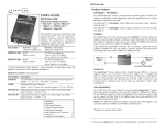
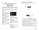
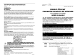
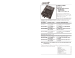
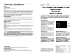
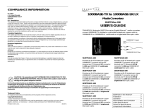
Minneapolis, MN 55344 USA
100BASE-TX/100BASE-FX
Multi-Port Media Converter
E-TX-FX-1200, E-TEL-1200, E-TX-FX-0600
COMPLIANCE INFORMATION
UL Listed
C-UL Listed (Canada)
CISPR/EN55022 Class A
FCC Regulations
This equipment has been tested and found to comply with the limits for a class A digital device, pursuant
to part 15 of the FCC rules. These limits are designed to provide reasonable protection against harmful
interference when the equipment is operated in a commercial environment. This equipment generates,
uses, and can radiate radio frequency energy and, if not installed and used in accordance with the
instruction manual, may cause harmful interference to radio communications. Operation of this
equipment in a residential area is likely to cause harmful interference, in which case the user will be
required to correct the interference at the user’s own expense.
Canadian Regulations
This digital apparatus does not exceed the Class A limits for radio noise for digital apparatus set out on
the radio interference regulations of the Canadian Department of Communications.
Le présent appareil numérique n'émet pas de bruits radioélectriques dépassant les limites applicables
aux appareils numériques de la class A prescrites dans le Règlement sur le brouillage radioélectrique
édicté par le ministère des Communications du Canada.
European Regulations
Warning
This is a Class A product. In a domestic environment this product may cause radio interference in which
case the user may be required to take adequate measures.
Achtung !
Dieses ist ein Gerät der Funkstörgrenzwertklasse A. In Wohnbereichen können bei Betrieb dieses Gerätes
Rundfunkstörungen auftreten, in weichen Fällen der Benutzer für entsprechende Gegenmaßnahmen
werantwortlich ist.
Attention !
Ceci est un produit de Classe A. Dans un environment domestique, ce produit risque de créer des
interférences radioélectriques, il appartiendra alors à l’utilsateur de prende les measures spécifiques
appropriées
CAUTION: RJ connectors are NOT INTENDED FOR CONNECTION TO THE
PUBLIC TELEPHONE NETWORK. Failure to observe this caution could result in
damage to the public telephone network.
Der Anschluss dieses Gerätes an ein öffentlickes Telekommunikationsnetz in den EG-Mitgliedstaaten
verstösst gegen die jeweligen einzelstaatlichen Gesetze zur Anwendung der Richtlinie 91/263/EWG zur
Angleichung der Rechtsvorschriften der Mitgliedstaaten über Telekommunikationsendeinrichtungen
einschliesslich der gegenseitigen Anerkennung ihrer Konformität.
Trademark Notice
All registered trademarks and trademarks are the property of their respective owners.
Copyright Restrictions
© 1999 TRANSITION Networks.
All rights reserved. No part of this work may be reproduced or used in any form or by any means –
graphic, electronic, or mechanical – without written permission from TRANSITION Networks.
Printed in the U.S.A.
33134.B
USER’S GUIDE
The rack-mountable E-TX-FX-1200, E-TEL-1200, and E-TX-FX-0600 series
multi-port media converters with LinkAlert™* allow the network
administrator of a large and complex network to extend the distances
between multiple sets of 100BASE-TX and 100BASE-FX devices.
TP LINK
FBR LINK
TP LINK
FBR LINK
1
TP LINK
FBR LINK
2
3
TP LINK
FBR LINK
4
TP LINK
FBR LINK
TP LINK
FBR LINK
5
6
TP LINK
FBR LINK
TP LINK
FBR LINK
7
TP LINK
FBR LINK
8
9
TP LINK
FBR LINK
10
TP LINK
FBR LINK
TP LINK
FBR LINK
11
12
POWER
ACT
ACT
ACT
ACT
ACT
ACT
ACT
ACT
ACT
ACT
ACT
ACT
E-TX-FX-1200 (shown) Provides twelve (12) independent media converter
connections between Fast Ethernet™ over twisted-pair copper (twelve RJ-45
connectors) and Fast Ethernet™ over singlemode or multimode fiber (twelve
fiber connectors, selected as a set according to network requirements).
E-TEL-1200 (not shown) Provides twelve (12) independent media converter
connections between Fast Ethernet™ over twisted-pair copper (one 50-pin Telco
connector) and Fast Ethernet™ over singlemode or multimode fiber (twelve fiber
connectors, selected as a set according to network requirements).
E-TX-FX-0600 (not shown) Provides six (6) independent media converter
connections between Fast Ethernet™ over twisted-pair copper (six RJ-45
connectors) and Fast Ethernet™ over singlemode or multimode fiber (six fiber
connectors, selected as a set according to network requirements).
Fiber Cable/Connector Options* by Model:
E-TX-FX-xx00/E-TEL-1200: multimode fiber, ST connectors
E-TX-FX-xx00(SC)/E-TEL-1200(SC): multimode fiber, SC connectors
E-TX-FX-xx00(MT)/E-TEL-1200(MT): multimode fiber, MT-RJ connectors
E-TX-FX-xx00(SM)/E-TEL-1200(SM): singlemode fiber, SC connectors
E-TX-FX-xx00(LH)/E-TEL-1200(LH): singlemode fiber, SC connectors
*See page 9 for detailed specifications.
*The LinkAlert™ feature allows each
media converter port to pass link faults
between connected 100BASE-TX and
100BASE-FX devices.
E-TX-FX-xx00 in the Network . . . . . .2
Installation . . . . . . . . . . . . . . . . . . . .4
Operation . . . . . . . . . . . . . . . . . . . . .6
Fault Isolation and Correction . . . . .8
Cable Specifications . . . . . . . . . . . . .9
Technical Specifications . . . . . . . . .11
Compliance Information . . . . . . . . .12
RJ-45 CONNECTOR
E-TX-FX-XX00 IN THE NETWORK
Twisted pair connection requires two active pairs configured as straight
through and/or crossover. The two active pairs in an Ethernet™ network are
pins 1 & 2 and pins 3 & 6. Use only dedicated wire pairs (such as blue/white
& white/blue, orange/white & white/orange) for the active pins.
Crossover
Straight Through
Twisted Pair #1
1
2
1
2
Twisted Pair #2
3
6
3
6
Server
Switch
TP LINK
FBR LINK
TP LINK
FBR LINK
1
Full-Duplex
Full-Duplex
Half-Duplex
ACT
TP LINK
FBR LINK
2
ACT
3
TP LINK
FBR LINK
ACT
4
TP LINK
FBR LINK
ACT
TP LINK
FBR LINK
5
6
ACT
TP LINK
FBR LINK
Full-Duplex
ACT
TP LINK
FBR LINK
7
ACT
TP LINK
FBR LINK
8
ACT
9
TP LINK
FBR LINK
10
ACT
TP LINK
FBR LINK
Full-Duplex
ACT
TP LINK
FBR LINK
11
Twisted Pair #2
3
6
3
6
TECHNICAL SPECIFICATIONS
Half-Duplex
12
POWER
ACT
1
2
NOTE: The multi-port media converter AutoCross™ feature allows either straightthrough or crossover twisted-pair copper cable to be used when connecting to
10BASE-T devices. AutoCross™ determines the characteristics of cable
connections to the media converter port and then automatically configures the
port to link up.
H
Half-Duplex
Twisted Pair #1
1
2
Standards
IEEE 802.3 1998 Edition
Case Dimensions
19.0" x 8.5" x 1.5"
(483 mm x 216 mm x 38 mm)
Environment
Temperature:
0-50°C (32° to 122° F )
ACT
Half-Duplex
Hub
Humidity
10-95%, non condensing
Altitude
0-10,000 feet
Power
100-240 VAC, 50/60 Hz., 1 Amp (maximum)
Warranty
Lifetime
DECLARATION OF CONFORMITY
Hub
Name of Mfg:
H
Server
Each media converter port in the multi-port media converter operates
independently over one isolated twisted-pair copper/fiber-optic cable
link. The media converter port receives and transmits network signals in
either full-duplex or half-duplex, depending upon the network devices
to which the media converter port is attached.
NOTE: In Telco option (not shown), the 50-pin Telco connector
concentrates up to 12 UTP connections onto one connector. This
concentration of UTP ports is then broken out for connection to fiber.
Transition Networks
6475 City West Parkway, Minneapolis MN 55344 USA
Model:
E-TX-FX-xx00, E-TEL-xx00 Series Multi-Port Media Converter
Part Number(s):
E-TX-FX-0600, E-TX-FX-0600(SC), E-TX-FX-0600(SM), E-TX-FX-0600(LH),
E-TX-FX-0600(MT), E-TX-FX-1200, E-TX-FX-1200(SC), E-TX-FX-1200(SM),
E-TX-FX-1200(LH), E-TX-FX-1200(MT), E-TEL-1200, E-TEL-1200(SC),
E-TEL1200(SM), E-TEL-1200(LH), E-TEL-1200(MT)
Regulation:
EMC Directive 89/336/EEC
Purpose: To declare that the E-TX-FX-0600, E-TX-FX-1200 or E-TEL-1200 to
which this declaration refers is in conformity with the following standards.
EMC-CISPR 22: 1985 Class A; EN 55022: 1988 Class A; EN 50082-1:1992;
EN 60950 A4:1997; IEC 801.2, IE C 801.3, and IEC 801.4; IEC 950
I, the undersigned, hereby declare that the equipment specified above conforms to the
above Directive(s) and Standard(s).
_September 3, 1999_____
Stephen Anderson, Vice-President of Engineering
Date
Media Converter Port in Full-Duplex Network
CABLE SPECIFICATIONS (continued)
In a full-duplex network, maximum cable lengths are determined by the
cables used. See page 10 for cable specifications.
COPPER CABLE
Each RJ-45 connector requires 2 pairs of Category 5 rated cable.
The 50-pin Telco connector requires 24 pairs of Category 5 rated
cable.
Either shielded twisted-pair (STP) or unshielded twisted-pair (UTP) can
be used. DO NOT USE FLAT OR SILVER SATIN WIRE.
CATEGORY 5:
Gauge
Attenuation
Maximum Cable Distance:
24 to 22 AWG
22.0 dB /100m @ 100 MHz
Telco
75 meters
RJ-45
100 meters
TELCO CONNECTOR
1
25
26
50
TELCO SIGNALS
Pin # Signal
1
Port 1 Transmit 2
Port 1 Receive 3
Port 2 Transmit 4
Port 2 Receive 5
Port 3 Transmit 6
Port 3 Receive 7
Port 4 Transmit 8
Port 4 Receive 9
Port 5 Transmit 10 Port 5 Receive 11 Port 6 Transmit 12 Port 6 Receive 13 Port 7 Transmit 14 Port 7 Receive 15 Port 8 Transmit 16 Port 8 Receive 17 Port 9 Transmit 18 Port 9 Receive 19 Port 10 Transmit 20 Port 10 Receive 21 Port 11 Transmit 22 Port 11 Receive 23 Port 12 Transmit 24 Port 12 Receive 25 N.C.
Pin #
26
27
28
29
30
31
32
33
34
35
36
37
38
39
40
41
42
43
44
45
46
47
48
49
50
Signal
Port 1 Transmit +
Port 1 Receive +
Port 2 Transmit +
Port 2 Receive +
Port 3 Transmit +
Port 3 Receive +
Port 4 Transmit +
Port 4 Receive +
Port 5 Transmit +
Port 5 Receive +
Port 6 Transmit +
Port 6 Receive +
Port 7 Transmit +
Port 7 Receive +
Port 8 Transmit +
Port 8 Receive +
Port 9 Transmit +
Port 9 Receive +
Port 10 Transmit +
Port 10 Receive +
Port 11 Transmit +
Port 11 Receive +
Port 12 Transmit +
Port 12 Receive +
N.C.
NOTE: The 512-Bit Rule described below does NOT apply in a full-duplex
network.
Media Converter Port in Half-Duplex Network
The 512-Bit Rule applies separately to each collision domain.
USING THE 512-BIT RULE
In a half-duplex network, maximum cable lengths are determined by the
round trip delay limitations of each Fast Ethernet™ collision domain.
(Switches and routers divide the network into separate Ethernet™
collision domains.) The 512-Bit Rule determines maximum distances by
calculating the collision domain round-trip delay in bit-times.
To calculate a collision domain round-trip delay in bit-times, find the
longest path between any two
terminal devices in the collision
Class I repeater
140 BT
Class II repeater
92 BT
domain. Calculate the round
Class I TX/FX media converter 130 BT
trip delay by multiplying the
Class II TX/FX media converter
92 BT
length of the cable (in meters)
DTE (PC, switch, router)
50 BT
by the delay per meter (in bitE-TX-FX-xx00 port
15 BT
times (BT)), then take the sum of
1 meter CAT.5 TP cable
1.11 BT
1 meter fiber cable
1 BT
all cable delays plus station
Fast Ethernet switch
50 BT
(DTE), repeater, and multi-port
media converter port delays. If
the result is less than or equal to 512 bit-times, the path is good.
200 meters fiber
@ 1.0 BT/meter
= 200BT
DTE= 50BT
10 meters TP
@ 1.11BT/meter
= 11.1BT
Class II
Hub
= 92BT
50.00BT
+11.10BT
+92.00BT
DTE= 50BT
+200.00BT
+15.00BT
+11.10BT
+50.00BT
__________
_
= 439.20BT
Half-Duplex Collision Domain
NOTE: Media converter
port is 15 bit-times IN
and 15 bit-times OUT =
30 bit-times round-trip.
10 meters TP
@ 1.11BT/meter
= 11.1BT
Half-Duplex Collision Domain
50.00BT
+11.10BT
+140.00BT
150 meters fiber
+150.00BT
@ 1.0 BT/meter
+15.00BT
= 150BT
+11.10BT
+50.00BT
__________
Class I
_
Hub
= 140BT = 437.20BT
10 meters TP
@ 1.11BT/meter
= 11.1BT
E-TX-FX-xx
Port
= 15BT
E-TX-FX-xx
Port
= 15BT
E-TX-FX-xx
Port
= 15BT
DTE= 50BT
10 meters TP
@ 1.11BT/meter
= 11.1BT
Switch/
Router
= 50BT
Full-Duplex - NO Collision Domain
INSTALLATION
CABLE SPECIFICATIONS
Install E-TX-FX-xx00 at Site
WARNING: During the site installation, handle the E-TX-FX-xx00 in such a
way that the E-TX-FX-xx00 does not fall. Failure to observe this warning
could result in injury to personnel and/or equipment damage.
To install the E-TX-FX-xx00 in 19-inch rack cabinet:
2
1
TP LINK
FBR LINK
TP LINK
FBR LINK
1
TP LINK
FBR LINK
2
3
TP LINK
FBR LINK
4
TP LINK
FBR LINK
TP LINK
FBR LINK
5
6
TP LINK
FBR LINK
TP LINK
FBR LINK
7
TP LINK
FBR LINK
8
9
TP LINK
FBR LINK
10
TP LINK
FBR LINK
TP LINK
FBR LINK
11
12
POWER
ACT
ACT
ACT
ACT
ACT
ACT
ACT
ACT
ACT
ACT
ACT
3
1.
Install right and left mounting brackets to E-TX-FX-xx00 chassis by
removing two (2) screws from each side of E-TX-FX-xx00 chassis
and then installing those screws through mounting bracket into ETX-FX-xx00 chassis.
2.
Carefully align the E-TX-FX-xx00 between rack mounting rails.
3.
Install E-TX-FX-xx00 in rack by installing two (2) screws through
right front bracket into rack and two (2) screws through left front
bracket into rack, using clip nuts (NOT provided) if necessary.
To install the E-TX-FX-xx00 on table or other flat surface:
NOTE: Rubber feet are provided.
1.
2.
Carefully turn E-TX-FX-xx00 to side.
Install four (4) rubber feet:
•
Separate rubber feet.
• Remove protective
paper from adhesive
surface on rubber foot.
• Position and secure
each rubber foot as
shown.
3.
Return E-TX-FX-xx00 to upright position.
Fiber Cable
MULTIMODE
Fiber Optic Cable Recommended:
Optional:
NOTE: Brackets and screws are provided.
ACT
The physical characteristics of the media cable must meet or exceed IEEE 802.3 specifications,
1998 Edition.
Bit error rate:
E-TX-FX-xx00, E-TEL-1200
Fiber-optic Transmitter Power:
Fiber-optic Receiver Sensitivity:
Link Budget
Typical Maximum Cable Distance:*
E-TX-FX-xx00(SC), E-TEL-1200(SC)
Fiber-optic Transmitter Power:
Fiber-optic Receiver Sensitivity:
Link Budget
Typical Maximum Cable Distance:*
E-TX-FX-xx00(MT), E-TEL-1200(MT)
Fiber-optic Transmitter Power:
Fiber-optic Receiver Sensitivity:
Link Budget
Typical Maximum Cable Distance:*
62.5 / 125 µm multimode fiber
100 / 140 µm multimode fiber
85 / 125 µm multimode fiber
50 / 125 µm multimode fiber
≤10-11
1300 nM
min: -19.0 dBm
max: -14.0 dBm
min: -30.0 dBm
max: -14.0 dBm
11.0 dB
2 kilometers
1300 nM
min: -19.0 dBm
max: -14.0 dBm
min: -30.0 dBm
max: -14.0 dBm
11.0 dB
2 kilometers
1300 nM
min: -19.0 dBm
max: -14.0 dBm
min: -33.5 dBm
max: -14.0 dBm
14.5 dB
2 kilometers
SINGLEMODE
Fiber Optic Cable Recommended:
Bit error rate:
E-TX-FX-xx00(SM), E-TEL-1200(SM)
Fiber-optic Transmitter Power:
Fiber-optic Receiver Sensitivity:
Link Budget
Typical Maximum Cable Distance:*
E-TX-FX-xx00(LH)**, E-TEL-1200(LH)**
Fiber-optic Transmitter Power:
Fiber-optic Receiver Sensitivity:
Link Budget
Typical Maximum Cable Distance:*
9 µm singlemode fiber
≤10-11
1300 nM
min: -15.0 dBm
max: -8.0 dBm
min: -31.0 dBm
max: -8.0 dBm
16.0 dB
20 kilometers
1300 nM
min: -8.0 dBm
max: -2.0 dBm
min: -34.0 dBm
max: -7.0 dBm
26.0 dB
40 kilometers
*Actual distance dependent upon physical characteristics of network installation.
**Requires a minimum loss of 5 dB over cable or damage to receiver may occur.
FAULT ISOLATION and CORRECTION
If the multi-port media converter fails, isolate and correct the fault by
determining the answers to the following questions and then taking the
indicated action:
1.
NOTE: Refer to page 10 for cable and connector specifications.
COPPER
NOTE: KEEP TWISTED PAIR RUNS AS SHORT AS POSSIBLE.
Is the POWER LED on the multi-port media converter
illuminated?
1.
Locate or build 100BASE-TX compliant cables with male RJ-45
plug connectors at both ends.
NO
2.
Connect male RJ-45 plug connector at one end of cable to media
converter port RJ-45 jack connector.
3.
Connect male RJ-45 plug connector at other end of cable to
100BASE-TX device RJ-45 jack connector.
•
•
•
Is the power cord properly installed in the media converter and in
the grounded AC outlet?
Does the grounded AC outlet provide power?
Contact Technical Support: (800) 260-1312/(800) 526-9267.
YES
•
2.
Install Cable
Proceed to step 2.
1.
Locate or build 100BASE-FX compliant fiber cable with male twostranded TX to RX connectors at both ends.
Check twisted pair cables for proper connection.
Contact Technical Support: (800) 260-1312/(800) 526-9267.
2.
Connect male TX and RX cable connectors at one end of cable to
TX and RX female connectors, respectively, on media converter
port.
Proceed to step 3.
3.
Connect male TX and RX cable connectors at other end of cable to
RX and TX connectors, respectively, on 802.3 compliant fiber
device.
Are any of the 100BASE-TX TX LINK LEDs illuminated?
YES
•
•
FIBER
NO
•
3.
Are any of the 100BASE-FX FBR LINK LEDs illuminated?
YES
•
•
•
Check fiber cables for proper connection.
Verify that TX and RX cables on media converter are connected to
RX and TX ports, respectively, on other device.
Contact Technical Support: (800) 260-1312/(800) 526-9267.
Connect to Power
NO
•
4.
Proceed to step 4.
Are any of the 100BASE-FX ACT (Activity) LEDs illuminated?
NO
•
•
•
Disconnect and reconnect the 100BASE-FX cable to restart the
initialization process.
Restart the workstation to restart the initialization process.
Contact Technical Support: (800) 260-1312/(800) 526-9267.
YES
•
Contact Technical Support: (800) 260-1312/(800) 526-9267.
1.
At multi-port media converter back, locate male power receptacle.
2.
Plug female media converter end of power cord into multi-port
media converter power receptacle.
3.
Plug male outlet end of power cord into correct voltage, properly
grounded, AC rack or wall power source.
4.
Verify that multi-port media converter is powered by observing
illuminated power and status LED(s).
Using LinkAlert™
OPERATION
Use the status LEDs to monitor multi-port media converter operation in the
network.
NOTE: Each 100BASE-TX/ 100BASE-FX media converter port is identified by
a number located just above the fiber connector(s) for that 100BASE-TX
/100BASE-FX port connection. The LEDs that apply to each 100BASE-TX or
100BASE-FX port connector(s) are located, when facing the multi-port media
converter, at the left of the connector(s) for that 100BASE-TX or 100BASE-FX
port connection.
TP LINK
FBR LINK
TP LINK
FBR LINK
1
TP LINK
FBR LINK
2
The E-TX-FX-xx00 series multi-port media converter LinkAlert™ feature allows
each media converter port to pass 100BASE-TX-side link faults over the port link
to the 100BASE-FX side and to pass 100BASE-FX-side link faults over the port
link to the 100BASE-TX side.
If the port does not detect a good link on the 100BASE-TX side, the port disables
all transmission (including active-idle) on the 100BASE-FX side.
Idle
Media Converter
Port
100BASE-TX
Device
100BASE-FX
Device
POWER
ACT
T(WISTED) P(AIR) LINK
ACT
ACT
Steady green LED indicates good link on
100BASE-TX copper.
F(I)B(E)R LINK
Steady green LED indicates good link on
100BASE-FX fiber.
ACTIVITY
Flashing green LED indicates 100BASE-TX
OR 100BASE-FX activity.
POWER
Steady green LED indicates connection to
external AC power.
If the port does not detect a good link on the 100BASE-FX side, the port disables
all transmission (including active-idle) on the 100BASE-TX side.
100BASE-TX
Device
Idle
Media Converter
Port
100BASE-FX
Device