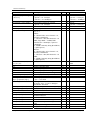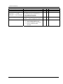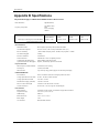
1
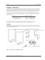
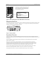
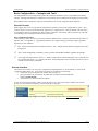
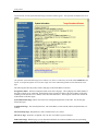
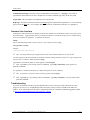
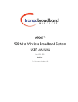
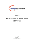
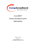
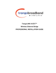
TrangoLINK-10
Point to Point
Wireless Ethernet Bridge
USER MANUAL
June, 2007
Revision E 3.0
Table of Contents
Trango
Table of Contents
Table of Contents .................................................................................................................................................. ii
Preface...................................................................................................................................................................iv
FCC Information .......................................................................................................iv
Warranty Information ...............................................................................................iv
Chapter 1 Overview................................................................................................................................................1
Contents .................................................................................................................. 1
Ethernet and Serial Ports.......................................................................................... 2
Operational Overview............................................................................................... 2
Chapter 2 Getting Started .......................................................................................................................................3
Connections and Power ............................................................................................ 3
Basic Configuration - Concepts and Tools .................................................................. 4
Opmode Concept...................................................................................................... 4
Browser Interface..................................................................................................... 4
Command Line Interface........................................................................................... 6
Troubleshooting ....................................................................................................... 6
Serial Port................................................................................................................ 7
Changing Password .................................................................................................. 7
Chapter 3 Configuration .........................................................................................................................................8
Essentials to Establish a Wireless Link ........................................................................ 8
Master Unit Configuration.......................................................................................... 8
Settings ................................................................................................................... 9
Master Unit Configuration Screen............................................................................... 9
Remote Unit Configuration Screen .......................................................................... 10
Basic Diagnostics .................................................................................................... 11
Master Unit’s System Information ............................................................................ 12
Remote Unit System Information ............................................................................ 15
Chapter 4 Deployment & Installation...................................................................................................................17
Site Selection......................................................................................................... 17
Site survey ............................................................................................................. 17
Channel Planning ................................................................................................... 18
Installation ............................................................................................................ 18
Mounting Hardware ................................................................................................ 18
Cabling and Weather Considerations ....................................................................... 20
Weatherizing.......................................................................................................... 21
RU Installation and Antenna Alignment ................................................................... 21
RU Antenna Alignment Procedure ........................................................................... 21
Chapter 5 Management.........................................................................................................................................23
RU Management ..................................................................................................... 23
SNMP ..................................................................................................................... 23
Objects for Monitoring and Control ......................................................................... 24
SNMP Setup............................................................................................................ 25
Appendix A
Appendix B
Command Set Summary ...........................................................................................................26
Specifications............................................................................................................................29
Trango Broadband Wireless — TrangoLINK User Manual Rev. E 3.0
page ii
Table of Figures
Trango
Table of Figures
Figure 1:
Figure 2:
Figure 3:
Figure 4:
Figure 5:
Figure 6:
Figure 7:
Figure 8:
Figure 9:
Components of a TrangoLINK-10 System ............................................................................ 1
Back of Radio (Shows where MAC address can be found)................................................... 2
Bottom of Radio..................................................................................................................... 2
Wiring Diagram ..................................................................................................................... 3
Pin-outs for Serial Cable ........................................................................................................ 7
Mounting Hardware Assembly ............................................................................................ 19
Alternative Mounting Hardware Assembly ......................................................................... 19
Mounting Articulation ......................................................................................................... 20
Grounding Example ............................................................................................................. 20
Table of Tables
Table 1: Reference Table of Master Unit System Information Parameters......................................... 12
Table 2: Reference Table of Remote Unit System Information Parameters ....................................... 15
Trango Broadband Wireless — TrangoLINK-10 User Manual Rev. D for F/W Ver. 1.1
page iii
Preface
FCC Information
Preface
This manual covers the basic configuration and installation of the TrangoLINK-10 Wireless Broadband System, and
applies to the following radio part numbers:
P5830S-MU
P5830S-RU
Master Unit with internal sectoral patch antenna
Remote Unit with internal patch antenna
Also available is the TrangoLINK-10-EXT, which does not include an internal antenna. The TrangoLINK-10-EXT
consists of a P5830S-MU-EXT and a P5830S-RU-EXT, and must be used in conjunction with an FCC certified external
antenna (sold separately). Instead of an internal antenna, the P5830S-RU-EXT has two Reverse Polarity SMA RF
Connectors for the attachment of external antenna cables. Contact your sales person for more information regarding the
“Professional Installation Guide.”
FCC Information
This device complies with Part 15 of the FCC Rules and Regulations. Operation is subject to the following two
conditions: (1) This device may not cause harmful interference, and (2) this device must accept any interference received,
including interference that may cause undesired operation.
This equipment has been tested and found to comply with the limits for a Class B digital device, pursuant to Part 15 of the
FCC Rules. These limits are designed to provide reasonable protection against harmful interference in a residential
installation. This equipment generates, uses, and can radiate radio-frequency energy and, if not installed and used in
accordance with these instructions, may cause harmful interference to radio communications. However, there is no
guarantee that interference will not occur in any particular installation. If this equipment does cause harmful interference
to radio or television reception, which can be determined by turning the equipment off and on, the user is encouraged to
correct the interference by one of more of the following measures:
1)
2)
3)
4)
Reorient the antenna.
Increase the separation between the affected equipment and the unit.
Connect the affected equipment to a power outlet on a different circuit from that which the receiver is connected to.
Consult the dealer and/or experienced radio/TV technician for help.
FCC ID: NCYM5830SSU
FCC ID: NCYM5830SSUEXT
IMPORTANT NOTE:
Intentional or unintentional changes or modifications must not be made unless under the express consent of the party
responsible for compliance. Any such modifications could void the user’s authority to operate the equipment and will
void the manufacturer’s warranty. To comply with FCC RF exposure requirements, the following antenna installation and
device operating configurations must be satisfied. The antenna for this unit must be fixed and mounted on outdoor
permanent structures with a separation distance of at least two meters from all persons. Furthermore, it must not be colocated or operating in conjunction with any other antenna or transmitter.
Warranty Information
Radios from Trango Broadband Wireless are warranted for one year from date of purchase. Please see
www.trangobroadband.com for a complete description of warranty coverage and limitations.
Trango Broadband Wireless — TrangoLINK-10 User Manual Rev. D for F/W Ver. 1.1
page iv
Overview
Warranty Information
Chapter 1 Overview
Your TrangoLINK-10 system provides the latest innovations in high-speed fixed wireless broadband. TrangoLINK-10 is
a point-to-point (PtP) system, which provides network connectivity at speeds up to 10 Mbps with a range of 40 miles
depending on the antenna configuration. TrangoLINK-10 operates in the 5.8 GHz ISM In this document, and within
the radio configuration itself, the designators of “ISM” and “U-NII” are used to distinguish between the two bands.
The following table shows approximate maximum ranges (at recommended fade margins) achievable with the
TrangoLINK-10 system using various antenna configurations. Longer ranges are achievable, but will result in
lower fade margins.
Antenna
Integrated / Internal Antenna (18 dBi)
15" Patch Antenna (24 dBi)
36" Dish Antenna (31 dBi)
ISM 5725 – 5850 MHz
10 Miles (w/ 10 dB fade margin)
20 Miles (w/ 15 dB fade margin)
40 Miles (w/ 21 dB fade margin)
The TrangoLINK-10 system consists of two types of radios: Master Units (MU) and Remote Units (RU).
The MU and RU conform to the maximum radiated power limits as established by the FCC.
Contents
Each TrangoLINK-10 kit comes equipped with two radios, two power-over-Ethernet (PoE) J-Box, two AC adapters, a
serial programming cable, and mounting hardware. Dual-polarized integrated antennas are located behind the radomes of
both the P5830S-MU and P5830S-RU.
Radio (MU and RU) antenna
Power Supply (120 VAC-24 VDC)
Power-over-Ethernet Injectors
Serial Programming Cable
Figure 1: Components of a TrangoLINK-10 System
Trango Broadband Wireless — TrangoLINK-10 User Manual Rev. E 3.0
page 1
Overview
Operational Overview
The only way to tell MUs and RUs apart is by the
model number printed on the backside product
label. This label also contains the MAC address
and serial number of the radio.
Trango Broadband Wireless
P5830S-MU
Rev. A
S/N: 000001421
MAC: 00 01 DE 00 02 F3
FCC ID: NCYM5830SM
Canada: XXXXXXXXXX
This equipment has been tested and found to comply with the limits for a Class B
digital device, pursuant to Part 15 of the FCC Rules. These limits are
Figure 2: Back of Radio (Shows where MAC address can be found)
Ethernet and Serial Ports
At the bottom of the radio are two access ports: a twist-on weatherproof cable port for RJ-45 Ethernet (and PoE), and an
access cover plug for the RJ-11 serial port. Behind the access cover plug are three LEDs that provide RF link-status
information. These LEDs are discussed later in this text.
Figure 3: Bottom of Radio
Operational Overview
TrangoLINK-10 MU is a sophisticated broadband wireless device that provides a host of comprehensive tools and
functions. The MU typically resides at the managing end of the network and performs all management functions for the
associated RU.
In order to establish a wireless link between the MU and the RU, the system administrator must set up the MAC
address of the RU in the MU.
When power is first applied to a properly installed RU, it will scan all channel/polarization combinations
searching for an MU. Once the RU detects the MU it will stop scanning and lock onto the channel of the MU
and begin transmitting using maximum RF power. Before the MU can wirelessly connect to the RU, it must
authenticate the RU by verifying the MAC address and performing a ranging operation to the RU.
Upon successfully authenticating and ranging the RU, the MU will adjust the RF transmit power in the RU
based on the Target RSSI parameter in the MU. This process is referred to as “power leveling.”
At this point the MU and RU are “associated” and Ethernet traffic will pass over the wireless link.
Trango Broadband Wireless — TrangoLINK-10 User Manual Rev. E 3.0
page 2
Getting Started
Connections and Power
Chapter 2 Getting Started
First unpack your MU and RU. It is recommended that you first provision and test your the radios on the bench before
deploying them in the field. This is a particularly useful exercise for the novice user.
Connections and Power
Connection and powering of the radios is the same for MUs and RUs.
• Connect a Cat-5 (straight through) Ethernet cable (we recommend shielded twisted pair) between the ODU (out
door unit) port of the J-box and the RJ-45 connector on the radio. Note that this cable will carry power-overEthernet (PoE).
•
If connecting to a COMPUTER, use a Cross-Over Ethernet cable from the NET port of the J-box to the
computer’s Ethernet port.
If connecting to a HUB, SWITCH, or ROUTER, use a Straight-Thru cable.
•
Plug the AC adapter into an AC outlet.
Figure 4: Wiring Diagram
Both green LEDs on the J-box should be lit, indicating power is present at the J-box as well as the radio.
You are now ready to configure the radio via the Ethernet port.
Note: If you cannot access the radio management functions via the Ethernet port, it is possible that your PC is not
set up with a properly routable subnet. If you forget the radio’s IP address, or for some other reason cannot access
the radio via the Ethernet port, use the Serial Programming cable (supplied with each TrangoLINK kit) and attach it
to the RJ-11 port located behind the access cover on the bottom of the radio.
Trango Broadband Wireless — TrangoLINK-10 User Manual Rev. E 3.0
page 3
Getting Started
Basic Configuration - Concepts and Tools
Basic Configuration - Concepts and Tools
The TrangoLINK-10 can be configured using either the Command Line Interface (CLI), or the Web Browser (HTTP)
interface. Although both methods are comprehensive and powerful, the CLI method provides slightly more functionality.
Both methods of radio configuration require an understanding of the concept of Operation Mode (Opmode).
Opmode Concept
Before logging into a radio, it is important to understand the “Opmode” concept of the TrangoLINK-10 system. MUs
and RUs can be in one of two operational modes: Opmode “On” or Opmode “Off.” When in Opmode “Off” the radio is
not transmitting, and it is not attempting to make a wireless connection. Alternatively, when in Opmode “On,” the radio
is transmitting, and is attempting to make a wireless connection.
Why is Opmode Important?
Certain functions, such as the site survey function and the RU RSSI function, can only be performed while the radio is in
Opmode “Off.” See Appendix A – Command Set Reference for a complete listing of commands, and the appropriate
Opmode(s) for each command.
Note: Factory Default Opmode for both MUs and RUs is “Off.” Default Opmode should be changed before radios
are deployed.
Note: Serial management (via the RJ-11 port) is possible on both MUs and RUs regardless of Opmode.
Note: Beginning with firmware version v1.1, TLINK-10 radios allow TCP/IP management access to both MU and
RU regardless of Opmode. V1.1 firmware also allows TCP/IP management access to the MU from the RU side of
the link (if wireless link is established).
Browser Interface
The Web browser interface is an easy-to-use, configuration and management tool. Its functionality is a subset of the
commands available in the CLI. To use the browser interface, you must have the following:
• An Ethernet connection between a PC and the radio (see figure 4)
• Setup your Ethernet PC connection to the subnet that is routable to the radio (default IP
address=192.168.100.100)
• A web browser (i.e. Microsoft Internet Explorer)
In order to use the browser interface, simply connect the radio to a PC, and type the radio’s IP address into the web
browser (i.e. Microsoft Internet Explorer). This will bring up a login page.
Type the password (default trango) and continue. This will bring up the radio’s System Information page.
Trango Broadband Wireless — TrangoLINK-10 User Manual Rev. E 3.0
page 4
Getting Started
Log into the MU, and the System Information page with info and status appears. The equivalent command for the CLI is
sysinfo.
This particular System Information page is for a Master Unit, which is evidenced by the model number P5830S-M in the
top left. To navigate through the various screens simply click on the underlined hyperlinks on the left hand side of the
page.
The following describes the primary features and pages of the HTTP Browser interface:
Navigation Column: The blue rectangular column on the left of all pages. The top displays the model number of
the radio to which you are connected. On the bottom of the Navigation Column is the Current Status of the radio,
including current Opmode, active channel, remote ID, and remote status. The navigation column also contains all
of the hotlinks to the other pages.
System Information Page: Shows most of the basic configuration parameters of the radio. It is the first page
shown after login.
Configuration Page: The essential parameters, such as IP address, remote unit ID, channel, and polarization, are
set here.
Advanced Setup Page: RF parameters, such as Transmit Power, are set here.
Site Survey Page: From here, in Opmode “Off,” the user can conduct a spectrum analysis.
Link Control Page: With this page you can determine which SUs are connected, and how they are performing.
Trango Broadband Wireless — TrangoLINK-10 User Manual Rev. E 3.0
page 5
Getting Started
Command Console Page: Runs any console command that is not interactive (i.e. ipconfig). The results are
reported back on the HTTP screen. For a complete list of console commands, type "help" in the entry field.
Logout Link: This will end the current HTTP session with the radio.
Help Page: The Browser Interface features useful Help pages that explain all listed parameters. To access the help
pages click on the Help link. For a complete description on the use of the Browser Interface, see Appendix A.
Command Line Interface
Although most radio functions can be managed via the browser interface, the command line interface (CLI) does provide
more functionality. Logging into the radio via command line interface is covered here briefly, but for a complete listing
of all CLI commands see Appendix A - Command Line Interface.
Telnet
Open a command prompt (DOS) session on your PC. Open a Telnet session by typing:
telnet [ip address of radio]
Example:
C:>telnet 192.168.100.100
Note: All Trango radios are pre-configured at the factory with a default IP address of 192.168.100.100.
You will be greeted with current hardware and firmware information and prompted for a password. Type in the password
and press enter. The factory default password is trango.
To terminate a CLI session (Telnet or Serial) type the command logout.
Note: Type help or ? for a listing of all CLI commands. Type help [<command>], for the syntax of a
particular command.
See Appendix A Command Set Summary for complete description of all CLI commands.
Note: To terminate a CLI session (Telnet or Serial) type the command logout.
Note: Type help, or ?, for a listing of all CLI commands. Type help <command>, to see the syntax of that
particular command.
Troubleshooting
If you can not telnet into the radio or open an HTTP browser session, check your cable connections to ensure
proper use of cross-over vs. straight-through cable, and ensure your PC’s subnet is routable to the radio’s IP
address. If you still cannot access the radio’s management interfaces, consult the troubleshooting guide available
at http://www.trangobroadband.com/support/appnotes_web.htm
Trango Broadband Wireless — TrangoLINK-10 User Manual Rev. E 3.0
page 6
Getting Started
Serial Port
TrangoLINK-10 Master Units and remote Units
feature a serial port. The serial port is useful in the
event that the radio cannot be accessed via TCP/IP
(HTTP or Telnet). A Terminal Emulation program
(such as HyperTerminal on the Windows operating
system) can be used to access the radio’s CLI using
the radio’s serial port, which is located behind the RJ11 access cover on the bottom of the radio. A serial
programming cable has been provided with each
TrangoLINK-10 for this purpose. To terminate a CLI
session (Telnet or Serial) type the command logout.
Type help or ? for a listing of all CLI commands.
Type help [<command>], for the syntax of a
particular command.
Figure 5: Pin-outs for Serial Cable
Terminal Settings
Changing Password
Use the CLI command _password to change the password.
Syntax: _password <newpassword> <newpassword>
example:
#> _password banana77 banana77
Update flash successful.
Success.
If you forget the password, the only way to reset the password is via the serial interface according to the following
procedure:
1. Connect your computer to the radio with the provided serial cable.
2. Open a HyperTerminal session on your computer.
3. Power cycle the radio.
4. While it is loading, you will be able to see this in HyperTerminal, press enter.
5. Type resetpassword.
6. Type main. This will continue the loader.
7. The password will be reset to trango.
Trango Broadband Wireless — TrangoLINK-10 User Manual Rev. E 3.0
page 7
Configuration
Essentials to Establish a Wireless Link
Chapter 3 Configuration
This section describes how to establish a basic wireless link between the MU and the RU, using the Browser
(HTTP) Interface. This section addresses only the most basic steps in establishing a link in the lab, or a bench-top
environment. It is highly recommended that you read the other sections of this manual to gain an understanding of
all important configuration parameters and procedures prior to deploying any wireless equipment.
In this section you will:
• Learn about MU and RU Basic Configuration Screens and Parameters
• Enter RU’s MAC address in the MU
• Configure Other Basic MU Parameters
• Configure Basic RU Parameters
• Establish a Wireless Link
• Evaluate Link Quality
The TrangoLINK-10 uses the concept of “association” to indicate that the MUs and RUs are communicating. If all
parameters are properly set, the RU will begin “listening” on each channel & polarization for an MU with its MAC
address programmed. Once an active MU is detected, the authentication and association process will begin.
Essentials to Establish a Wireless Link
•
•
RU Mac Address must be programmed into the MU
MU & RU must be in Opmode “ON”
If both of these parameters are met, and if the MU and RU are within range and properly aligned, the wireless link
will automatically establish itself and Ethernet traffic will begin to pass between the radios.
Note: This section utilizes the Browser Interface as the configuration tool. For the equivalent CLI commands,
see Appendix A.
Master Unit Configuration
Open a browser session with the MU and click the configuration link.
Trango Broadband Wireless — TrangoLINK-10 User Manual Rev. E 3.0
page 8
Configuration
Essentials to Establish a Wireless Link
Settings
IP Address, Subnet Mask, and Gateway: The IP configuration of the radio for configuration and network
management purposes. Note that the IP settings in the TrangoLINK-10 are for radio management purposes only.
Default Opmode: Operation mode of the radio after a power cycle or reboot. When the radio enters Opmode
"ON," it will be transmitting. When the radio enters Opmode "OFF," the radio is not transmitting, but can be
accessed via the Ethernet port. The radio can be put into Opmode "OFF" regardless of its default Opmode by
telneting into it within the first 30 seconds after a power cycle or reboot.
Remote ID: Mac address of the remote unit (RU).
Block Broadcast Packets: If this switch setting is selected the MU will not pass broadcast or multicast packets
across the link with the exception of ARP and DHCP.
Auto Powerlevel Remote Unit: If this switch setting is selected the MU will control the transmit power of the
remote unit automatically based on the RU Target RSSI Setting (on the Advanced Setup page).
Active Channel/Polarization: The current channel and antenna polarization of the unit when in Opmode "AP."
Master Unit Configuration Screen
1.
2.
3.
4.
5.
6.
7.
Set IP, subnet, and gateway. (This is only necessary to manage the radios via TCP/IP.)
Fill in the Remote ID with the MAC address of the RU. (This is written on the label of the RU.)
Set channel and polarization. (The default is 1 H).
Set default Opmode to “ON” in the MU.
Select an active channel (or leave at default).
Update system setting flash memory by clicking Save and Activate Settings button.
Click Activate Opmode.
Trango Broadband Wireless — TrangoLINK-10 User Manual Rev. E 3.0
page 9
Configuration
Essentials to Establish a Wireless Link
Remote Unit Configuration Screen
Establish a browser session with the RU. Click on the configuration link and set the following parameters:
1.
2.
3.
4.
5.
Set IP, subnet, and gateway. (This is only necessary to manage the radios via TCP/IP.)
Set default Opmode to “ON” in the RU.
Leave “Auto Scan Master Unit” switch on, or set Active Channel to match MU.
Update system setting flash memory by clicking Save and Activate Settings button.
Click Activate Opmode.
At this point the RU will begin scanning all channels actively searching for the MU. Once the MU is detected, the
authentication and association process will begin.
Note: The RED LED on the bottom of the MU should be lit, indicating that the radio is in Opmode “ON” and is
transmitting.
Note: The amber light on the bottom of the RU indicates the relative signal strength (RSSI) of the signal received.
A steady light indicates a strong signal. A blinking light indicates weaker (although perhaps sufficient) signal
strength.
Trango Broadband Wireless — TrangoLINK-10 User Manual Rev. E 3.0
page 10
Configuration
Basic Diagnostics
Basic Diagnostics
Several tools are available on the Link Control page for diagnosing the quality of the wireless link.
RF Link Loopback Test: Sends 1600 byte packets to the RU at 50 millisecond intervals over the time specified and
reports a bandwidth measure in kbps.
Ranging/RSSI Test: Reports the distance of the link, and the RSSI.
Power Level Remote Radios: Adjusts the transmit power of the RU to attempt to bring the MU RSSI as close as
possible to the Target RSSI. Target RSSI can be adjusted on the Advanced Setup page.
Trango Broadband Wireless — TrangoLINK-10 User Manual Rev. E 3.0
page 11
Configuration
Basic Diagnostics
Master Unit’s System Information
An example of the MU’s system information screen along with a description of each of the most important changeable
parameters as well as related commands for the CLI are shown in the tables below.
Save and Activate Settings
Note: When changing settings, it is necessary to click
in order to update the
radio’s flash memory. If you do not, the setting will be lost the next time the radio is rebooted.
Trango Broadband Wireless — TrangoLINK-10 User Manual Rev. E 3.0
page 12
Configuration
Basic Diagnostics
Table 1: Reference Table of Master Unit System Information Parameters
Parameter
Hardware Version
FPGA Version and
Checksum
Firmware Version
Device ID
Opmode
Description
Hardware version is factory-set and cannot be
changed by user.
This parameter provides information about the
current FPGA firmware loaded in the radio.
The Firmware version is the initial four
characters of this string. (i.e. 1p60 = 1.60 )
MAC address of the radio.
Current operation mode of the radio. “On”
indicates transmitting. “Off” indicates not
transmitting.
Associated Page and Notes
Permanent with Hardware
See website for latest FPGA firmware and
release notes.
See website for latest firmware version and
release notes.
Permanent with hardware
Configuration page.
Note: in order to change the radio from
Opmode “On” to Opmode “Off,” you must
change the default Opmode to “Off,” and
reboot the radio.
CLI Commnand: opmode [<on | off>]
Default Opmode
System Up Time
Radio Temperature
[IP]
[subnet]
[gateway]
Determines the Opmode (“ON” or “OFF”) of the
radio after reboot/power cycle. When the
parameter is set to “ON,” the radio will progress
into Opmode “ON” automatically after
reboot/power cycle. Note: If radio startup is
interrupted within 30 seconds after reboot (by
opening a Telnet session) the radio will remain
in Opmode “OFF.”
Configuration page
Time since radio was last rebooted or power
cycled.
Current internal temperature of radio.
Informational Parameter
IP, subnet, and Gateway address of radio used to
manage the radio.
Telnet Port
TFTPD status
User changeable telnet port of radio.
Remote ID
MAC address of the Remote Unit
Status
Status of Remote Unit: Connected (wireless
link established), or Disconnected (wireless
link not established).
Relative Signal Strength Indicator. Displays
signal strength received from the MU to the
RU. A “?” indicates RU is not connected.
Master Unit to Remote Unit maximum
information rate (in kbps).
RSSI
Downstream MIR
Upstream MIR
TFTP daemon status (on or off). TFTPD should
be turned on to import a file (such as new
firmware) into radio’s TFTP buffer. Default is
off.
Remote Unit to Master Unit maximum
information rate (in kbps).
Trango Broadband Wireless — TrangoLINK-10 User Manual Rev. E 3.0
CLI Command:
set defaultopmode [<on | off>]
Informational Parameter
Configuration page
Note: Changing the IP of the radio could
cause loss of management connectivity.
CLI Command:
ipconfig[< ip> <subnet> <gateway>]
Configuration page
Configuration page
Note: TFTPD ON is used in firmware
upgrade process.
CLI Command: tftpd [<on | off>]
Configuration page
CLI Command: set remoteid <RU’s MAC>
Informational Parameter
Informational Parameter
CLI Command: rssi
Advanced page
CLI Command:
set mir [<downstream kbps, 100..10000>
<upstream kbps, 100..10000>]
Advanced page
CLI Command:
page 13
Configuration
Parameter
Basic Diagnostics
Description
Associated Page and Notes
set mir [<downstream kbps, 100..10000>
<upstream kbps, 100..10000>]
Downstream
Throughput
Upstream
Throughput
Current throughput from Master Unit to
Remote Unit.
Current throughput from Remote Unit to
Master Unit.
Active Channel
Current RF channel and polarization (v)ertical or
(h)orizontal.
Specifies the receiver sensitivity of the radio.
This user-changeable parameter is a powerful
tool that is useful for mitigating the effects of
interference. The radio will not process any
signals receieved that are weaker than the RF
RX threshold.
Transmit power of the radio (not including
antenna gain)
RF RX Threshold
RF TX Power
Channel Table
Assigns channel numbers to actual
frequencies of operation. The default channels
1 – 6 are assigned to ISM band. Note: All
channels may be re-assigned as desired by the
user. Default settings allow optimum use of
Informational Parameter
Informational Parameter
Configuration page
CLI Command: freq <ch> <pol>
Advanced page
CLI Command:
rfrxth <ism > <-90|-85|-80|-75|-70|-65>
Advanced page
CLI Command:
power <setism> <max |min| dBm>
Advanced page
CLI Command:
freq writechannel [<ch#> <freq>] ...
the available spectrum. The frequencies
assigned on the Master Unit must match those
on the Remote Unit.
Broadcast Packet
Filter
Remarks
Eth In
Eth Out
RF In
RF Out
This switch (0) enables/disables the blocking of
Ethernet control packets, except ICMP and ARP,
to reduce the amount of unnecessary overhead
introduced to the wireless link
User definable radio information (i.e. customer
name, address of installation, and so on).
Maximum 28 characters can be stored.
Eth In: Counter for Ethernet packets that
entered via the Ethernet port of the radio.
Counter for Ethernet packets that exited via
the Ethernet port of the radio.
Counter for Ethernet packets that entered
over-the-air into the radio.
Counter for Ethernet packets that exited overthe-air out of the radio.
Trango Broadband Wireless — TrangoLINK-10 User Manual Rev. E 3.0
Configuration page
CLI Command:
sw 0 [<on | off>]
Informational Parameter
CLI Command:
remarks <remarks>
Informational Parameter
Informational Parameter
Informational Parameter
Informational Parameter
page 14
Configuration
Remote Unit System Information
Remote Unit System Information
Log into the RU and the System Information page will appear. The user can change many of these parameters.
Note: When changing settings, it is usually necessary to click the Save and Activate Settings Button in order to
update the radio’s flash memory. If you do not, the setting will be lost the next time the radio is rebooted or power
cycled.
Table 2: Reference Table of Remote Unit System Information Parameters
Parameter
Hardware Version
FPGA Version and
Checksum
Firmware Version
Description
Hardware version is factory-set and cannot be
changed by user.
These parameters provide information about
the current FPGA firmware loaded in the
radio.
The Firmware version is the initial four
characters of this string. (i.e. 1p60 = 1.60 )
Device ID
Opmode
MAC address of the radio.
Current operation mode of the radio. “On”
indicates transmitting. “Off” indicates not
transmitting.
Default Opmode
Determines the Opmode (“ON” or “OFF”) of the
radio after reboot/power cycle. When the
parameter is set to “ON”, the radio will progress
into Opmode “ON” 30 seconds after
reboot/power cycle. Note: If radio startup is
interrupted within 30 seconds after reboot (by
opening a Telnet session) the radio will remain in
Opmode “OFF.”
System Up Time
Time since radio was last rebooted or power
cycled.
Current internal temperature of radio.
Radio Temperature
[IP]
[subnet]
[gateway]
Master ID
Status
RSSI
IP, subnet, and Gateway address of radio used to
manage the radio.
MAC ID of the MU that is associated to this RU.
Status of Master Unit: Connected (wireless
link established), or Disconnected (wireless
link not established).
Relative Signal Strength Indicator. Displays
signal strength received from the RU to the
MU. A “?” indicates MU is not connected.
TFTPD Status
TFTP daemon status (on or off). TFTPD should
be turned on to import a file (such as new
firmware) into radio’s TFTP buffer. Default is
off.
Telnet Port
RF TX Power
User changeable telnet port of radio.
Transmit power of the RU not including antenna
gain. The RU’s transmit power will
automatically be adjusted to result in receive
signal strength at the MU to approximately
Trango Broadband Wireless — TrangoLINK-10 User Manual Rev. E 3.0
Associated Page and Notes
Permanent with Hardware
Changes with FPGA upgrade. See
subsequent Release Notes on web site.
Changes with firmware upgrade. See
website for latest firmware version and
release notes.
Permanent with Hardware
Configuration page.
Note: in order to change radio from
Opmode “On” to Opmode “Off,” you must
change the default Opmode to “Off” and
reboot the radio.
Configuration page
CLI Command:
set defaultopmode [<on|off>]
Informational Parameter
Informational Parameter
Configuration page
Note: Changing the IP of the radio could
cause loss of management connectivity.
CLI Command:
ipconfig [<ip> <subnet> <gateway>]
Informational Parameter
Informational Parameter
Informational Parameter
Configuration page
Note: This is used in firmware upgrade.
CLI Command
tftpd [<on | off>]
Configuration page
Informational Parameter
page 15
Configuration
Parameter
RF RX Threshold
Active Channel
Broadcast Packet
Filter
MU Autoscan
TCP/IP for MU
Remarks
Remote Unit System Information
Description
match the RU’s RSSI Target setting. The user
does not manually set the RU’s transmit power.
Specifies the receiver sensitivity of the radio.
This user-changeable parameter is a powerful
tool that is useful for mitigating the effects of
interference. The radio will not process any
signals receieved that are weaker than the RF RX
threshold.
Current channel. If MU Autoscan feature is on,
and if the RU is not associated to an MU, it will
continue to cycle through all channels until it
detects and MU.
This switch (0) enables/disables the blocking of
Ethernet control packets, except ICMP and ARP,
to reduce the amount of unnecessary overhead
introduced to the wireless link.
This switch (1) is to turn MU Autoscan on or off.
This switch (2) when on, allows users at the MU
side of the network to telnet or HTTP into the
RU.
User definable radio information (i.e. customer
name, address of installation, and so on).
Maximum 28 characters can be stored.
Trango Broadband Wireless — TrangoLINK-10 User Manual Rev. E 3.0
Associated Page and Notes
Advanced page
CLI Command:
rfrxth <ism> <-90|-85|-80|-75|-70|-65>
Informational Parameter
Configuration page
sw 0 [<on | off>]
Configuration page
sw 1 [<on | off>]
Configuration
sw 2 [<on | off>]
Informational Parameter
page 16
Deployment & Installation
Site Selection
Chapter 4 Deployment & Installation
Once you are familiar with the basic operation of the radios you are ready for deployment in the field. The deployment
process consists of the following steps:
• Site Selection
• Site survey at MU and RU sites
• MU installation
• RU installation and antenna alignment
• Link test
Site Selection
Proper site selection for your MU will help ensure a successful deployment. Site selection will depend on a wide variety
of factors, but from the radio’s performance standpoint, please consider the following:
• Path from MU to RU should provide unobstructed line-of-sight (LOS), thus it is advisable to place MU as high
as possible on a tall building or tower.
• Ethernet cable limit is 100 meters from Ethernet device (router, switch) to radio.
• Radios should never be deployed without proper grounding.
• Consider nearby sources of interference that could degrade the performance of the radio. Mount radios as far
from sources of interference as possible.
Site survey
Both the MU and RU provide an on-board site survey tool. This tool will tell you if there is any interference present in
the 5.8 GHz band.
To use the survey tool, the radio must be in Opmode “OFF.” The survey can be performed for any specified amount of
time (in seconds), and for either the horizontal or vertical polarization.
Prior to performing the site survey, place the radio in the installation spot, and aim the radio in the desired direction.
After the specified period, the results of this command will provide you with a listing of each channel in the band, the
average signal received, and the maximum signal received during the survey period.
In general you will be looking for frequencies with signal strengths of –85 dBm or lower. If interference is present on
various channels, it is recommended that you chose clean channels or alternate polarizations for your deployment. If it is
not possible to use a clean channel/polarization combination, there are various methods available to mitigate the affects of
interference. These methods include the use of the RFRX THRESHOLD settings, or the use of external shields on the
MU. See the site survey example on following page.
Trango Broadband Wireless — TrangoLINK-10 User Manual Rev. E 3.0
page 17
Deployment & Installation
Channel Planning
Results are reported in dBm per channel as average and peak. A channel is reported to be “Clear” if the peak and
average are below the RF RX Threshold by more then 8 dB.
Channel Planning
For installations involving co-location of radios operating in the same band, channel planning is extremely important.
Use of the 5.8 GHz spectrum ISM band will allow maximum co-location potential.
See www.trangobroadband.com for additional information on channel planning schemes.
Installation
Once the site survey is completed, you are ready to install your radios. It is recommended to install the MU first. The
reason for this is that the RU has a built-in RSSI tool that will help you properly aim the RU at the MU to achieve
maximum signal strength.
Mounting Hardware
Both MUs and RUs are supplied with mounting hardware for pole installations. See diagram below for proper use of the
mounting hardware.
Trango Broadband Wireless — TrangoLINK-10 User Manual Rev. E 3.0
page 18
Deployment & Installation
Installation
1
2
3
4
5
ITEM
NO.
1
2
3
4
5
PART NUMBER
Not Supplied
QTY.
Radio
#10 x 3" Threaded Rod
#10 Keps Nut
"V" Bracket
1
4
8
2
Mono Pod Mount (Not Supplied)
1
Figure 6: Mounting Hardware Assembly
Alternate Mounting Configuaration
5
1
Not Supplied
2
3
4
ITEM
NO.
1
2
3
4
5
PART NUMBER
QTY.
Radio
#10 x 3" Threaded Rod
#10 Keps Nut
"V" Bracket
1
4
8
2
Mono Pod Mount (Not Supplied)
1
Figure 7: Alternative Mounting Hardware Assembly
Trango Broadband Wireless — TrangoLINK-10 User Manual Rev. E 3.0
page 19
Deployment & Installation
Installation
Standard Mounting
U p /D o w n
T ilt
Alternative Mounting
Up/Down Tilt
4 X M u st B e lo o se n e d fo r
U p / D o w n T i lt
Figure 8: Mounting Articulation
Proper mounting of the radio includes
consideration for grounding. Please note that if the
radio is attached to a metal pole that is earthgrounded, no other grounding is necessary. If the
radio is not earth-grounded via the mounting
bracket, you must attach a grounding wire to the
grounding stud on the back of the radio as in the
adjacent diagram.
Figure 9: Grounding Example
Cabling and Weather Considerations
Shielded twisted pair Cat-5 cable is recommended for all installations. The shield within the Cat-5 cable does not need to
be grounded if the radio itself is grounded. It is important to consider that most Cat-5 cable will deteriorate over time if
exposed to the weather (especially direct sunlight). It is recommended that installers place all Cat-5 cables inside conduit.
Plastic conduit is sufficient. If metal conduit is used, it is not necessary to use shielded Cat-5 cable.
Trango Broadband Wireless — TrangoLINK-10 User Manual Rev. E 3.0
page 20
Deployment & Installation
Weatherizing
Weatherizing
Important! If not using conduit, The Ethernet port compression washer on the 5830 series
radios should be loosely tightened around the cat-5 cable to allow pressure equalization
within the radio enclosure. Leave approximately 1 mm around the cat-5.
!
!
It is important to provide strain relief and drip loop for STP Cat-5 cables. Do not mount the
radio upside down.
!
Important! The J-Box is not a weatherized device and must be located either indoors or in a
weather-protected cabinet.
RU Installation and Antenna Alignment
Once the MU is installed, and aligned in the correct general direction, it is time to install the RU. The hardware
installation of the RU is identical to the MU, including considerations for line-of-sight, cable distances, cable type,
weather sealing, and grounding.
Once the RU is installed and aimed in the general direction of the MU, it is time to perform an RSSI test to determine the
signal strength from the MU, and to precisely align the RU antenna for maximum signal strength.
RU Antenna Alignment Procedure
1.
2.
3.
4.
5.
Ensure MU is in Opmode “ON.”
Connect to the RU from the Ethernet side via the Browser Interface.
Login and observe the RSSI indicator on the bottom left of the page. To update
this value press the F5 key. Alternatively, from the Telnet command line
interface, type the command rssi. As you read the RSSI reading, move the
antenna in the horizontal and vertical planes until the maximum RSSI reading is
achieved. For short links you can expect an RSSI of –60 dBm or better. For
longer links and RSSI of –75 dBm is acceptable. Any RSSI of less than –80
dBm may be too weak for the radios to reliably associate and pass data.
If it is not possible to receive an adequate RSSI reading, it may be necessary to
reorient the MU (up/down, left/right), to increase the output power of the MU,
or to move the RU to a location with better line-of-sight conditions to the MU.
Once you are satisfied with the RSSI reading, tighten down the RU in the
optimum position.
Note: The amber light on the bottom of the RU will also indicate RSSI according to
the following parameters:
not lit
RSSI< -80dBm
RSSI > -80dBm
blinking
RSSI ≥ -65dBm
solid (blink rate increases with signal strength)
Trango Broadband Wireless — TrangoLINK-10 User Manual Rev. E 3.0
page 21
Deployment & Installation
RU Installation and Antenna Alignment
Link Test
Ensure the RU’s default Opmode is “ON,” and that all configuration parameters are correct.
Reboot the radio. Once the radio enters Opmode “ON,” the authentication process will occur with the MU, and the two
radios will begin to associate. From the MU side, use the Link Control page to assess the quality of the link.
Enter a duration time for the RF Link Loopback / Speed Test. Click the “loopback test” button. The test will execute
and report the success rate (packets sent and received) after the duration period.
A similar test can be performed from the command line interface via the command ru speedtest.
Example:
#> ru speedtest
Some traffic may be dropped during testing.
Pkt Len = 1760 bytes, File Size = 10 MBytes, 5958 pkts
Press [space] then [enter] to stop
5
4
3
2
1
0
.+++*
.+++*
.+++*
.+++*
.+++*
.+++*
[M RxGood] 10486080 bytes [R RxGood] 10486080 bytes --> 16750 ms
10016 Kbps
Success.
#>
Trango Broadband Wireless — TrangoLINK-10 User Manual Rev. E 3.0
page 22
Management
RU Management
Chapter 5 Management
In the TrangoLINK-10 system, the MU controls most functions of its associated RU. For this reason it is important to consider
that you will manage your TrangoLINK-10 system primarily through the MU.
Network management can be performed by three methods
• Browser Interface
• CLI
Appendix A – Command Set Reference
• SNMP Manager
Discussed in this section.
RU Management
Most management functions of the RU can be performed by issuing commands from the MU.
As an example, to change the RUs IP, subnet, and gateway: ru ipconfig [ <new ip>][<new subnet>][<new gateway>]
Example: ru ipconfig 192.168.10.10 255.255.255.0 192.168.10.1
From the command line interface type ru for a listing of all ru commands. Example:
#> ru
[Remote ID] 00 01 DE 01 AD B5 [Status] connected [RSSI] -47 dBm
[Downstream MIR] 10000 kbps [Upstream MIR] 10000 kbps
[Downstream] 0 kbps [Upstream] 0 kbps
ru
ru
ru
ru
ru
ru
ru
ipconfig <new ip> <new subnet> <new gateway>
ping
powerleveling
reboot
speedtest [<pkt len (byte), 64..1760> [<file size (MBytes), 10, 100>]
sysinfo
testrflink [<pkt len, 64..1760>]
#>
A complete description of these commands and many others can be found in Appendix A – Command Set Reference.
SNMP
TrangoLINK-10 supports Simple Network Management Protocol (SNMP) for network management. Network management
consists of the following 4 categories: configuration, accounting, alarm, and monitoring and control. These capabilities allow
the network operator to provide superior services through higher network accessability and integrated accounting system. For
more information on SNMP and its uses, you can visit http://www.faqs.org/faqs/snmp-faq/.
The Trango SNMP solution supports MIB-II (system only) and the Trango proprietary Management Information Base (MIB).
SNMP agents reside on both the MU and RU.
Users interested in using the SNMP functionality should review the entire TrangoLINK-10 MIB for a complete understanding
of its features.
The following is an overview of a few of the more commonly used SNMP objects in the TrangoLINK-10 system.
Trango Broadband Wireless — TrangoLINK-10 User Manual Rev. E 3.0
page 23
Management
SNMP
Objects for Monitoring and Control
RU Bandwidth Monitoring
• ruEthRXAvgThroughputLog – Average payload data throughput (in Kbits/sec) received on the Ethernet port over
the period specified by ruStatisticsSamplePeriod (1 ~ 60 minutes).
• ruEthTXAvgThroughputLog - Average payload data throughput (in Kbits/sec) transmitted on the Ethernet port
over the period specified by ruStatisticsSamplePeriod (1 ~ 60 minutes).
• ruRfRXAvgThroughputLog - Average payload data throughput (in Kbits/sec) received on the RF link over the
period specified by ruStatisticsSamplePeriod (1 ~ 60 minutes).
• ruRfTXAvgThroughputLog - Average payload data throughput (in Kbits/sec) transmitted on the RF link over the
period specified by ruStatisticsSamplePeriod (1 ~ 60 minutes).
• ruRfInOctets – Number of octets of payload transmitted from MU’s RF port.
• ruRfOutOctets – Number of octets of payload received on MU’s RF port.
MU Bandwidth Monitoring
• mutrafficEthRXAvgThroughputLog – Average payload data throughput (in Kbits/sec) received on the Ethernet
port over the period of 1 minute.
• mutrafficEthTXAvgThroughputLog – Average payload data throughput (in Kbits/sec) transmitted on the Ethernet
port over a period of 1 minute.
• mutrafficRfRXAvgThroughputLog – Average payload data throughput (in Kbits/sec) received on the RF link over
a period of 1 minute.
• mutrafficRfTXAvgThroughputLog – Average payload data throughput (in Kbits/sec) transmitted on the RF link
over the period of 1 minute.
• mutrafficEthInOctets – Number of octets of payload received on the Ethernet port.
• mutrafficEthOutOctets – Number of octets of payload transmitted on the Ethernet port.
• mutrafficRfInOctets – Number of octets of payload received on the RF port.
• mutrafficRfOutOctets – Number of octets of payload transmitted on the RF port.
Link Status Monitoring –Various traps are defined as follows:
• Cold start – when SNMP agent starts running
• Link Up – when the MU enters Opmode “On”
• Link Down – when the MU reboots
• RU Link Up – when RU associates to the MU
• RU Link Down – when RU disassociates from the MU
• Opmode “On” Failure – when MU fails to enter Opmode “On”
MU and RU Control – SNMP also provides several control capabilities. The majority of the features available on the CLI are
also available via SNMP. Here are a few of these features:
• Add/delete remote
• Change channel
• Set power
• Set radio sensitivity
Review the Trango MIB (trango_P5830Sap_1p0.mib) for the complete listing of MIB Objects.
Trango Broadband Wireless — TrangoLINK-10 User Manual Rev. E 3.0
page 24
Management
SNMP
SNMP Setup
Trango Broadband provides only the MIB portion of the SNMP Management system. The radios act as individual agents, and
it is up the user to provide SNMP Manager software from a third party vendor. Below is an example of the setup process for
SNMPc from Castle Rock™.
1.
2.
3.
4.
5.
6.
Unzip trangopkg.zip file to a local temporary directory.
Go to your local temporary directory, you will see 4 files shown below.
a. trango_P5830Sap_1p0.mib – M5800S MU MIB file
b. trango.ico – P5830S MU icon
c. autoico.txt – instruction file (Selects Trango icon automatically during initial set-up.)
Copy trango_P5830Smu_1p0.mib file to C:\Program Files\SNMPc Network Manager\mibfiles
Copy autoico.txt file to C:\Program Files\SNMPc Network Manager\mibfiles
Copy trango.ico file to C:\Program Files\SNMPc Network Manager\bitmaps
The MIB needs to be compiled into the SNMPc database
By default, the Read Community is set to “public,” and Write Community is set to “private” in the MU. The Trap
Community is “SNMP_trap.” The manager needs to have the same settings in order to communicate with the MU
successfully.
Note: The Trap Community cannot be set via HTTP or CLI.
To send traps from the MU, set the following:
•
•
•
trap destination IP (Trango MIB object trapconfig–trapconfigInfo)
trap community string (Trango MIB object trapconfig–MutrpTable-MutrpEntry)
enable each trap (Trango MIB object traponfig–mutrpTable-MutrpEntry)
For all set operations, set object SaveAndActivate at musystem-musystemInfo to write the information to FLASH.
Trango Broadband Wireless — TrangoLINK-10 User Manual Rev. E 3.0
page 25
Command Set Summary
Appendix A Command Set Summary
•
•
•
OFF = Opmode “OFF,” ON = Opmode “ON”
s = serial, e = Ethernet
+ It may not work properly through HTTP’s command console.
Command
!+
?
? <command>
_password <new password>
<new password>
arp –bcast [<on | off>]
baud [<9600 | 115200>]
bye
eth <link | r | w | reset>
exit
freq
freq <ch#> <h | v>
freq channeltable
freq writechannel [<ch #>
<freq>]…
heater [<on temp, 0..19> <off
temp, 1..20>]
help
help <command>
ipconfig [<new ip> <new subnet
mask> <new gateway>]+
logout
maclist macexp <30..600>
maclist filter [<on | off>]
maclist [<reset>]
msearch <sec> <ch#>
<h | v>…
opmode [<on | off>]
password
ping <ip address>
Description
redo the last command
same as “help”
same as “help”
specify new password (max 15octs)
enables/disables the sending of periodic arp
broadcast packets to gateway
display or set console baud rate
same as “logout”
display or set Ethernet setting
same as “logout”
display current channel
change current channel and polarization
display channel table
build channel and write to flash
<ch #> = 1..30
set heater parameters
display complete help page except “eng”
search and display command’s help
assign radio’s IP, subnet mask, and
gateway IP
logout of console
change expiration time of MAC entry in
maclist
filter out all local Ethernet packets
display or reset current MAC table
Master search – RU will search for MU on
specified channel and polarization.
set or display current Opmode
specify new password (max 15octs)
ping local Ethernet device
OFF
s
se
se
se
ON
s
se
se
se
se
se
se
se
se
se
se
se
se
se
se
se
se
se
se
se
se
se
se
se
se
se
se
se
se
se
se
se
se
se
se
se
se
se
se
se
s
se
se
s
se
se
se
se
se
power
power <setism>
<min | max | dBm>
display default and current TX power level
specify TX power for both band
ru ipconfig <new ip> <new
subnet> <new gateway>
ru ping
ru powerleveling
assign Remote ipconfig
se
ping Remote Radio
power levels RU to reach Target RSSI, set
in MU
se
se
Trango Broadband Wireless — TrangoLINK-10 User Manual Rev. E 3.0
Remark
default = 9600 bps
AP’s default is 600s
SU’s default is 30s
default: on
It only works for local
Ethernet devices, not
SU or any device behind
SU.
default = +18 dBm
SU’s power will be
adjusted by MU when
association
page 26
Command Set Summary
Command
ru reboot
ru speedtest [<packet length>
<file size>]
ru sysinfo
ru testrflink [<packet length>]
reboot
remarks [<str>]
reset [<all | 0…n>]…
rfrxth <ism> <-90 | -85 | -80 | 75 | -70 | -65>
rfrxthreshold …
rssi
save
save mm
save ss
set defaultopmode [<on | off>]
set httpport [<port #>]
set mir [<downstream,
kbps>][<upstream, kbps>]
set rssitarget <dB>
set snmpcomm [<read | write>]
set telnetport [<port #>]
ssrssi <ch #> <v | h>
survey <ism> <time, sec> <h|v>
sw 0 [<on | off>]
sw 1 [<on | off>]
sw 2 [<on | off>]
sw 3 [<on | off>]
sysinfo
temp
Description
reboot Remote Radio
perform speedtest
<pkt len> = 64..1760 bytes
<file size> = 10..100 Mbytes
request Remote’s system information
perform RF loopback test testrflink
<pkt len> = 64..1760 bytes
reboot unit
string length should be 1 to 28 characters
reset radio to the firmware default
n# = 0..2
Master:
0 - Channel Table, Active Channel = 1 h,
Switches, and Remarks
1 - TX Power = Max, RF Threshold = -90
dBm, Target RSSI = -60 dBm, MIR
Downstream = 10000 kbps, Upstream =
10000 kbps
2 - SNMP Community String (Read/Write)
= (public/private)
Remote:
0 - Channel Table, Active Channel = 1 h,
Switches, and Remarks
1 - TX Power = Max, RF Threshold = -90
dBm
2 - SNMP Community String (Read/Write)
= (public/private)
specify RF RX Threshold
OFF
same as “rfrxth”
display current RX RSSI
same as “updateflash”
same as “updateflash mainimage”
same as “updateflash systemsetting”
set or display default Opmode
set or display HTTPD port number
set or display MIR
<kps> = 100..10000
set Target RSSI Threshold
It must be -45 to –75, and +5 dB higher
than RF RX Threshold.
display or assign SNMP community string
specify telnet port, <port #> = 1..65534
display RSSI on the current channel
spectrum analysis of entire RF band
set sw #0 – packet filter for
broadcast/multicast
set sw #1 – HTTPD service
set sw #2 – Auto scan Master signal
set sw #3 – Auto power leveling Remote
Unit
display system configuration
display current temperature
Trango Broadband Wireless — TrangoLINK-10 User Manual Rev. E 3.0
ON
se
se
se
se
Remark
default:
<pkt len> = 1760 bytes
<file size> = 10 MBytes
default:
<pkt len> = 1760 bytes
se
se
se
se
se
se
se
se
se
se
se
se
se
se
se
se
se
se
se
se
se
se
se
se
se
se
se
se
se
se
se
default = 23
se
default = on
se
se
se
se
se
se
default = on
default = on
default = on
se
se
se
se
default = -90 for both
band
default = 80
page 27
Command Set Summary
Command
tftpd [<on | off>]
tm
updateflash <mainimage |
fpgaimage> <* | current
chscksum> <* | new checksum>
updateflash systemsetting
ver
Description
enable or disable TFTPD service
display current time mark
get image from TFTP buffer, verify
checksum and write to flash memory at
main or FPGA image section
*: skip checksum verification
write current configuration into flash
memory at system configuration section
displays firmware version info:
1. version number and date code
2. firmware and FPGA version code
3. firmware and FPGA image
checksum
Trango Broadband Wireless — TrangoLINK-10 User Manual Rev. E 3.0
OFF
se
se
se
ON
se
se
se
se
se
se
se
Remark
page 28
Specifications
Appendix B Specifications
All specifications apply to P5830S-R and P5830S-M unless otherwise noted.
Radio Parameters
High Band (ISM)
5725 MHz to 5850
MHz
6 non-overlapping
channels
Frequency of Operation
Antenna Gain
Max Range / Fade Margin (5.8 Ghz ISM Band)
Antenna Beamwidth (azimuth)
Internal Antenna
DSS Dish
15" Patch
36" Dish
18 dBi ISM Band
24 dBi
24 dBi
31 dBi
10 Miles./ 10 dB
20 Miles /15 dB
20 Miles/15 dB
40 Miles /21 dB
18o
9o
9o
4o
Data Parameters
Modulation Format
Direct Sequence Spread Spectrum (DSSS) with RAKE
Certification/Compliance
FCC Part 15.247, 15.407 AP only: ETSI/EN301 489-1 (7.2)
Receiver Sensibility
(1E10-6 BER) 1600 byte packets: -83 dBm, 64 byte packets: -87 dBm
User Data Throughput
10 Mbps
Format 10/100 BaseT
10/100 BaseT
Network Protocols
All IEEE 802.3 / 802.3u compliant protocols
Configuration and Management
Telnet, SNMP, TFTP, HTTP, Serial
Upstream/Downstream Throughput
Dynamic, automatically adjusts to suit demand
Physical Interfaces
Ethernet Speed (via RJ45 shielded)
10/100 BaseT, Auto-sensing
Serial Speed
(via RJ11) 9600 baud
Ethernet Packet
Up to 1600 byte long packets (supports VLAN/VPN pass through)
POWER PARAMETERS
Power Method
Power over Ethernet (PoE). DC Voltage injected at PoE J-Box
Voltage input limits into PoE J-Box
12 VDC - 24 VDC, 20 VDC Nominal
Voltage input limits into Radio
10.5 VDC - 21 VDC
Standard Power Supply (included)
120 VAC to 20 VDC
PoE Cat-5 Max Cable length
100 meters on 24 AWG STP Cat-5 Cable
Current Draw/Power
670 mA max. (13.4 W), using 20V standard adapter
Environmental
Radio Enclosure
All-weather, powder coated, cast aluminum w/polycarbonate radome
Temperature Range
-40° to 60° C (-40° to 140° F)
NEMA Rating
NEMA 4
Radio Dimensions
12.5 in. x 8 in. x 2.75 in.
Radio Weight
4 Lbs.
User Interfaces
RJ45 (shielded) and RJ11
Trango Broadband Wireless — TrangoLINK-10 User Manual Rev. E 3.0
page 29