1
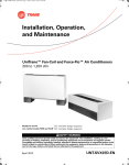
Classroom Unit Ventilator Accessories
Accessories from A to Z
Wall Boxes, Energy Recovery System,
Shelving, Side Wall Exhaust, Gravity Relief
Damper
March 2006
UV-PRC005-EN
Introduction
Unit Ventilator Accessories
from A to Z
As a leader in applied unit ventilator
systems, Trane brings more than just
an authentic approach for HVAC design to the drawing table. Trane also
provides aesthetically pleasing solutions through their matching classroom accessories. Trane accessories
are intended to complement the unit
ventilator in order to provide a complete classroom system to the administrative staff.
Our full line of add-on accessories enhance the classroom unit ventilator
system by affording a seamless approach to a classroom layout.
Trane’s accessories include:
• Shelving
• Pipe covers
• Gravity relief damper (exhaust
stale air naturally from the classroom).
• Side wall power exhaust system
(exhaust stale air mechanically
from the classroom).
• and Unit ventilator energy recovery system (treats and filters incoming fresh air into the
classroom as well as exhausts
stale air from the classroom).
Trane has over 80-years of application
and design experience with indoor
comfort system. Our offices are
staffed with HVAC engineering professionals ready to work with you and
your system designer to help determine the best solution for your school.
• Wall boxes
©2006 American Standard Inc All rights reserved
UV-PRC005-EN
Table of
Contents
Introduction
2
Features and Benefits
4
Application Considerations
9
Model Number Description
10
Shelving
10
Energy Recovery Ventilator
11
Side Wall Exhaust / Gravity Relief Damper
12
General Data
13
Performance Data
14
14
Electrical Performance
Controls
UV-PRC005-EN
15
Energy Recovery Control Operation
15
Wiring
16
Dimensional Data
19
Mechanical Specifications
30
3
Features and Benefits
Energy Recovery Unit Ventilator
Energy Recovery Unit
Ventilator
Air conditioning systems have always
had one primary responsibility: deliver
sufficient amounts of conditioned air
into buildings. As indoor air quality issues grow proportionally, along with
the rising cost of energy, more is being
asked of these air conditioning systems.
To provide your facility with the best
possible balance of energy efficiency,
air quality and comfort, Trane offers
an energy recovery unit ventilator.
The job of the unit ventilator energy
recovery system is to provide every
room with the right amount of fresh air
necessary to comply with IAQ standards like ASHRAE 62, while minimizing installed cost and energy use. To
do this, it uses a desiccant-coated
wheel to transfer both sensible heat
and moisture from outside air to exhaust air in the summer, and from exhaust air to the incoming outside air in
the winter.
Traditionally, there has been a choice
when bringing in outdoor air. Either locally, or through centralized ventilation systems. With the unit ventilator
energy recovery system, the ductwork
associated with centralized systems is
eliminated, and possible humidity and
energy consumption problems encountered when locally introducing
outside air are also decreased.
Leading unit ventilator technology for
decades, Trane has developed a unit
ventilator that is as cost-effective, as it
is IAQ-smart.
4
Equipment Size
The energy recovery system allows up
to 500 cfm of outside air to be brought
into the space without putting a large
ventilation load on the unit ventilator
system.
The fresh air damper is a positive closure damper operated by a 24-volt, 3point floating control motor. The exhaust air damper is a gravity relief type
damper in order to help avoid overpressurization of the classroom.
Cabinet Finish
The unit cabinetry is made of a durable
industrial grade metal to withstand
student contact. An appliance grade
paint treatment increases the aesthetics of the equipment while making it
long-lasting for typical classroom environments.
Defrost Controls: In most cases,
Trane’s ultra low leak dampers effectively protect against unwanted air infiltration and possible desiccant wheel
frosting. Yet many buildings face outdoor air temperatures lower than 10°F
while still requiring outdoor air. For
this reason, the energy recovery unit
ventilator may be equipped with a
unique defrost control. Electric preheat is used to prevent frost from
building up on the heat exchange
wheel and other components.
An interior pipe channel on the energy
recovery unit ventilator allows the installer to easily connect the HVAC’s
unit ventilator piping with existing
system piping.
Access
A single panel access design of the
unit is easily removable, and provides
complete access to the unit fan, wheel,
filter, and controls.
Fan and Motor Assembly
Fans for the energy recovery unit ventilator are double-inlet, forwardcurved centrifugal variety. They have a
maximum speed of 1,050 rpm with
permanent split capacitor motors. The
fan housing is constructed of heavy
gauge metal to help reduce air noise
during operation. Wheel motors are
single-speed, permanent split capacitor with overload protection. Each fan
is equipped with a three speed switch
for air balancing.
Ultra Low Leak Dampers
An ultra-low leak, blade type outside
air damper is installed on every energy
recovery unit ventilator system. This
helps ensure low leakage of the outside air when the equipment is off. The
unit is available with two separate
damper assemblies.
Filters
Each unit comes equipped with two
separate filters. Depending on usage,
the outside air filters can either be 1 or
2-inches thick (disposable or pleated
style). They are easily removed,
thrown away and replaced. There is
also a 1-inch thick throwaway filter for
exhaust air.
Subbases
Subbases may be ordered to create
the desired height of the equipment if
mating up to an existing or retrofit application.
Controls
The unit may be controlled through
the ZN520 controller, or through a 24V
binary signal. All units are shipped
from the factory fully assembled, and
run-tested to assure that a quality
product is delivered.
UV-PRC005-EN
Features and Benefits
Energy Recovery Unit Ventilator
Air-to-Air Heat Exchanger
The air-to-air heat exchanger is designed to support two separate air
streams in a counter-flow direction.
The heat exchanger matrix prevents
less than one percent of cross contamination between the air streams. The
heat exchanger has the effectiveness
of up to 80-percent with equal airflow.
For extremely cold climates, it may be
necessary to provide a means to prevent the wheel from frosting. The controls for the electric preheat are
interlocked with a differential pressure
switch to prevent the element from
coming on without the fan operating.
The electric preheat (frost prevention)
kW should be sized based on the winter design dry bulb temperature and
the frost threshold temperature. See
selection procedure section to acquire
the sizing equation.
UV-PRC005-EN
5
Features and Benefits
Shelving
Unit Ventilator Shelving
Trane’s unit ventilator shelving was inspired by the needs of a classroom setting. The design supports applications
from simple book or file storage to a
draft barrier design. Piping compartments, a choice in tops and cut-to-fit
fillers creates a custom approach to
the space design. Trane’s shelving is
easy to install, and durable enough to
withstand even the most rigorous
classroom environment.
Cabinet Finish
The unit cabinetry is made of a durable
industrial grade metal to withstand
typical student wear/tear. An appliance grade paint treatment increases
the aesthetics of the equipment while
making it long-lasting.
All selections are equipped with leveling legs for proper matching to the
classroom unit ventilator, energy recovery system or side wall exhaust
system.
For units that include a dynamic (draft)
barrier design, a floor spacer will be installed at the back of the shelving unit
in order to block air flow under the
unit.
Each shelving component ships from
the factory with a standard set of installation hardware to help minimize
the need for field supplied components.
The Formica® top option is available
as a 1-inch particle board, finished with
a choice of Formica laminate to compliment and coordinate with paint color of the shelving unit. The laminate is
available in sections or continuous
lengths for a seamless appearance. A
flanged drop-in grille eliminates exposed edges, and is permanently fastened to prevent removal. The top may
be ordered with or without a grille.
An attractive metal top, painted in the
same color as the shelving unit, is a
low cost option to flatter the classroom space.
6
Trane Unit Ventilator Shelving Configurations:
Closed Shelving
The closed shelving design is
available in 2, 3, 4 and 5-feet lengths.
Shelving depth includes 16 5/8" or 21
1/4" to accommodate retrofit and new
equipment installations. The units are
equipped with adjustable shelves that
are reinforced with a formed channel
for maximum strength. Closed
shelving doors include two locks as
standard. A bottom door guide adds
stiffness and durability for the sliding
doors.
Open Shelving
The open shelving design is available
in 2, 3, 4 and 5-feet lengths. Shelving
depth includes
16 5/8" or 21 1/4" to accommodate
retrofit and new equipment
installations. The units are equipped
with adjustable shelves that are
reinforced with a formed channel for
maximum strength.
Cut-to-fit Filler
The cut-to-fit filler piece is designed
to fill the gaps between small spaces.
The filler is available in an 18" or 36"
length, and may be cut-to-fit an area
as small as 4-inches. The fill-in
section has a removable front panel
to allow access to piping or electrical
connections.
Piping Compartment
The piping compartment is equipped
with a metal top, leveling legs and a
locking front panel. It is a standalone
piece of equipment that is best suited
for housing piping equipment for the
unit ventilator.The compartment is
designed to attached to either end of
the unit ventilator.
Formica Laminate Top
The laminate top selection is available
in many decorative colors, and in
lengths up to 12-feet. The tops may be
cut in the field to match any specific
length requested. A Gator Ply™ underside seals out moisture that could
potentially cause warping. It is available with or without a grille.
UV-PRC005-EN
Features and Benefits
Side Wall Power Exhaust
Equipment Size
The side wall power exhaust provides
a nominal 500 (single fan) or 750 (dual
fan) cfm with a two speed switch. The
unit is available in a 15 1/4", 16 1/4" or
21 1/4" depth to support all retrofit and
new construction applications.
Side Wall Power Exhaust
Quick removal of concentrated air
contaminants and building pressurization are two reasons to include an
exhaust systems into the IAQ design.
Building areas that often contain a
build-up of these contaminants are
science labs, vocational/technical
shops, cafeterias, and indoor pools.
These areas should be maintained
under negative pressure relative to
adjacent spaces.
Trane’s side wall power exhaust system is designed to aid in the removal
of these contaminants from the classroom environment. As a standalone
unit design, the side wall power
exhaust may be utilized with or without the complete unit ventilation system. Unit control may also be
delivered through a ZN520 controller
connection, allowing the side wall
power exhaust to blend seamlessly
with the vertical unit ventilator system
to sustain complimentary unity of the
entire classroom design.
UV-PRC005-EN
Cabinet Finish
The unit cabinetry is made of a durable
industrial grade metal to withstand
typical student wear/tear. An appliance grade paint treatment increases
the aesthetics of the equipment while
making it long-lasting. Adjustable leveling legs are designed into the base
corners providing flexibility to mate
the unit with the unit ventilator, shelving or the energy recovery system.
The single front panel is secured by
three camlock fasteners.
A polyurethane gasket seal is placed
along the perimeter of the discharge
opening to secure the back draft
damper at the wall opening.
Motor and Drive
All motors are a two-speed, 115/60/1
voltage and fans are direct-drive. The
motors are permanently lubricated,
sleeve type bearings which do not require oiling.
Unit Switch
The unit’s on-off switch is housed in
the left hand end pocket below the discharge air grille.
7
Features and Benefits
Wall Boxes and Gravity Damper
Wall Boxes
Wall boxes are to be installed prior to
mounting the Classroom Unit Ventilator, Side Wall Exhaust, or Energy Recovery Unit Ventilator. Its intended use
is to help deter animals, trash, or rainfall from entering into the mechanical
system providing a year-round outdoor intake for the HVAC equipment.
Finish
Trane’s wall boxes are constructed of
heavy gauge aluminum and designed
to last the life of the building. Internal
parts are interlocked, in addition to being held securely in place by the
frame-within-a-frame design. This assures proper louver alignment.
Louvers are vertically or horizontally
aligned, and held in position by an integral spacing guide. The boxes are
available with an anodized aluminum
finish, or a baked enamel finish.
Wall box arrangements are furnished
with a diamond pattern, expanded aluminum bird screen to eliminate objects from blowing into the building.
The grilles are aluminum and the
same finish as the frame.
Wall Box Types
Trane offers a variety of wall boxes to
support different needs and applications. Each are sized to match the
classroom unit ventilator intake, and
may be ordered with or without a recessing flange. See dimensional data
for free area velocity of each wall box
design.
8
Gravity Relief Damper
The gravity relief damper is a barometrically operated design which prevents
over pressurization of the classroom.
The damper is typically located in a
plenum, or behind the 21 1/4" classroom shelving with a grilled top. An
optional wall box is recommended to
deter objects from easy entry into the
building.
Finish
Trane’s gravity relief damper is constructed from high grade aluminum
and is designed for durability and
long-stay. The dampers are horizontally arranged into the assembly.
Pipe Cover
The pipe cover assembly consists of
the pipe enclosure, mounting strip and
pipe hangers. It adds a decorative
touch to the room decor by removing
the supply/return/condensate pipe exposure.
The enclosure is constructed from
heavy gauge metal and finished to
match the classroom unit ventilator.
The steel cover is locked to the mounting strip with non-visible fasteners.
The mounting strip is a continuous roll
formed steel and contains a full length
channel for the enclosure. The pipe
hangers are .148-inch in diameter, zinc
plated steel wire. The hangers are designed to support up to two, 2 1/8" O.D.
insulated pipes.
UV-PRC005-EN
Application
Considerations
Energy Recovery Unit Ventilator
Operation
An energy recovery ventilator can
help make mechanical ventilation
more cost effective by transferring
energy between the outdoor air and
the building exhaust air.This desiccant-coated wheel revolves through
the outdoor and exhaust air streams.
During the cooling season, sensible
heat and moisture are transferred
from the outdoor air to the exhaust air
stream, and rejected from the building. During the heating season, sensible heat and moisture are transferred
from the exhaust air to the outdoor air
stream, heating and humidifying the
entering outdoor air.
In extremely cold climates, it may be
necessary to provide some means to
prevent the wheel from frosting.
Trane’s energy recovery unit ventilator
is equipped with a UL-listed electric resistance preheat element for frost prevention.
The controls for the electric preheat
coil are interlocked with a differential
pressure switch to prevent the element from coming on without the fan
operating.
The electric preheat coil should be
sized based on winter design dry bulb
temperature (TOA)and the frost threshold temperature (TTH). Example:
kW required
=
1.08 x 500 cfm x (TTH-TOA)
3134
Where frost threshold is determined
by the relative humidity of the space in
the winter.
Room Relative
Humidity
Frost Threshold Temp - TTH (F)
30%
5
40%
10
50%
15
After passing through the energy
recovery unit ventilator, the warmed
or cooled fresh air goes through the
classroom unit ventilator for further
air treatment.
UV-PRC005-EN
9
Model Number
Shelving
SHL B G 2 05 D0 0 F A D 0 0 0
5
DIGIT 1-3: UNIT CONFIGURATION
SHL = Classroom Shelving
DIGIT 4: DEVELOPMENT
SEQUENCE
B = Current Sequence
DIGIT 5: SHELVING STYLE
0 = Continuous Top ONLY/No
Shelving
2 = 18-inch Cut-to-Fit Filler
3 = 36-inch Cut-to-Fit Filler
4 = 12-inch Piping Compartment
5 = 18-inch Piping Compartment
A = 2-ft Open Shelving
B = 3-ft Open Shelving
C = 4-ft Open Shelving
D = 5-ft Open Shelving
E = 3-ft Closed Shelving
F = 4-ft Closed Shelving
G = 5-ft Closed Shelving
H = 3-ft Open Shelving
with Dynamic Air Barrier
J = 4-ft Open Shelving
with Dynamic Air Barrier
K = 5-ft Open Shelving
with Dynamic Air Barrier
L = 3-ft Closed Shelving
with Dynamic Air Barrier
M = 4-ft Closed Shelving
with Dynamic Air Barrier
N = 5-ft Closed Shelving
with Dynamic Air Barrier
DIGIT 6: SHELVING TOP DEPTH/
GRILLE
0 = Not Required
1 = 16 5/8-inch Shelving and Top
Depth
2 = 21 1/4-inch Top Depth w/o Grille
3 = 21 1/4-inch Top Depth w/ Steel
Grille
4 = 21 1/4-inch Top Depth
w/Aluminum Grille and Damper
5 = 21 1/4-inch Top Depth
w/Aluminum Grille
6 = 16 5/8-inch Deep Piping
Compartment
7 = 21 1/4-inch Deep Piping
Compartment
10
10
DIGIT 7&8: LENGTH of FORMICA
TOP
00 = No Formica Top for Shelving
Selected
01 = Formica Top w/Same Size and
Shelving
02 = 2-ft Top Only (no shelving)
03 = 3-ft Top Only (no shelving)
04 = 4-ft Top Only (no shelving)
05 = 5-ft Top Only (no shelving)
06 = 6-ft Continuous Top
07 = 7-ft Continuous Top
08 = 8-ft Continuous Top
09 = 9-ft Continuous Top
10 = 10-ft Continuous Top
11 = 11-ft Continuous Top
12 = 12-ft Continuous Top
18 = 18-inch Top Only (no shelving)
DIGIT 9&10: DESIGN SEQUENCE
Current Sequence
DIGIT 11: DECORATOR FORMICA
TOPS
0 = No Top
1 = Metal Top
A = Champagne Papyrus Formica®
Top
E = Almond Formica Top
F = Ivory Blushing Formica Top
G = Natural Canvas Formica Top
H = Glacier Slate Formica Top
J = Birch Formica Top
K = Folkstone Formica Top
M = Fog Formica Top
N = Tundra Terra Formica Top
Q = Stone Dust Formica Top
DIGIT 12: SHELVING PAINT
COLOR
0 = No Color Shelving Finish
A = Cameo White Shelving Finish
B = Soft Dove Shelving Finish
C = Deluxe Beige Shelving Finish
D = Driftwood Grey Shelving Finish
E = Rose Mauve Shelving Finish
F = Stone Grey Shelving Finish
G = Bronze Tone Shelving Finish
15
DIGIT 13: END COVERS
0 = No End Covers
A = 16 5/8-inch Deep End Covers
w/o Cutouts
B = 16 5/8-inch Deep End Covers
w/Std. Cutouts
C = 16 5/8-inch Deep End Covers
w/Extended Cutouts
D = 21 1/4-inch Deep End Covers
w/o Cutouts
E = 21 1/4-inch Deep End Covers
w/Std. Cutout
F = 21 1/4-inch Deep End Covers
w/Extended Cutouts
DIGIT 14: SUBBASE
0 = No Subbase Feature
2 = 2-inch Subbase
4 = 4-inch Subbase
6 = 6-inch Subbase
DIGIT 15: KICKPLATE
0 = Louver Front Kickplate (no side)
1 = Louver Front and Side Kickplate
2 = Solid Front Kickplate (no side)
3 = Solid Front and Side Kickplate
DIGIT 16: KEY LOCK
0 = Standard Lock
1 = Master Key for Lock
ADDITIONAL ACCESSORIES
SGRL: Extra Steel Grille
2ft: Extra 2-ft Steel Grille
3ft: Extra 3-ft Steel Grille
4ft: Extra 4-ft Steel Grille
5ft: Extra 5-ft Steel Grille
AGRL: Extra Aluminum Grille
2ft: Extra 2-ft Aluminum Grille
3ft: Extra 3-ft Aluminum Grille
4ft: Extra 4-ft Aluminum Grille
5ft: Extra 5-ft Aluminum Grille
UV-PRC005-EN
Model Number
Energy Recover Unit Ventilator
ERS A 050 2 0 A0 0 A 1 2 1 0 0 CA
5
DIGIT 1-3: UNIT CONFIGURATION
ERS = Energy Recovery System
DIGIT 4: DEVELOPMENT
SEQUENCE
A = First Generation
DIGIT 5-7: NOMINAL CAPACITY
050 = 500 CFM
DIGIT 8: UNIT INCOMING POWER
SUPPLY
1 = 120V/1-Phase Power Supply
2 = 208V/1-Phase Power Supply
3 = 240V/1-Phase Power Supply
4 = 277V/1-Phase Power Supply
DIGIT 9: ETL LISTING
0 = No ETL Listing
1 = ETL Listing
DIGIT 10&11: DESIGN SEQUENCE
Current Design
DIGIT 12: ELECTRIC DEFROST
0 = None
2 = 1.00 kW 208V/1-Phase
3 = 2.00 kW 208V/1-Phase
4 = 2.44 kW 208V/1-Phase
5 = 1.07 kW 240V/1-Phase
6 = 2.00 kW 240V/1-Phase
7 = 3.25 kW 240V/1-Phase
8 = 1.42 kW 277V/1-Phase
9 = 2.73 kW 277V/1-Phase
A = 3.25 kW 277V/1-Phase
UV-PRC005-EN
10
15
DIGIT 13: SUPPLY-AIR INLET to
UNIT VENT
A = LH Inlet to UV (4-Pipe, Pipe
Chase)
B = RH Inlet to UV (4-Pipe, Pipe
Chase)
C = LH Inlet to UV (2-Pipe, Pipe
Chase)
D = RH Inlet to UV (2-Pipe, Pipe
Chase)
DIGIT 14: DAMPER
CONFIGURATION
0 = No Damper
1 = Backdraft Damper on Exhaust
2 = Shut-Off Damper on Supply
3 = Backdraft Damper on Exhaust &
Shut-Off Damper on Supply
DIGIT 15: Controls
1 = Field Supplied/End Device
2 = Field Supplied w/Economizer
3 = TracerTM ZN520 Controls
20
DIGIT 18: END COVER
0 = No End Cover
DIGIT 19: SUBBASE
0 = No Unit Subbase
A = 2-inch Subbase
B = 4-inch Subbase
C = 6-inch Subbase
DIGIT 20: OPEN DIGIT
0 = Open Digit
DIGIT 21: WALL BOX and WALL
BOX FINISH
00 = No Wallbox
CA = Clear Anodized Finish
LB = Light Bronze Finish
MB = Medium Bronze Finish
DB = Dark Bronze Finish
B1 = Brick (BR1) Finish
B3 = Brick (BR3) Finish
B5 = Brick (BR5) Finish
WH = White Finish
BL = Black Finish
DIGIT 16: SUPPLY-AIR FILTER
SIZE
2 = 1-inch Pleated Media (Std.)
DIGIT 17: COLOR SELECTION
1 = Deluxe Beige
2 = Cameo White
3 = Soft Dove
4 = Stone Grey
5 = Driftwood Grey
11
Model Number
Side Wall Exhaust/Gravity Damper
SWE A 050 1 0 E0 V1 LB A 1 0 1 0 1
5
DIGIT 1-3: UNIT CONFIGURATION
SWE = Side Wall Exhaust
SWG = Gravity Relief Damper
DIGIT 4: DEVELOPMENT
SEQUENCE
A = Current Sequence
DIGIT 5: UNIT SIZE
CAB = Cabinet Only
050 = 500 CFM (SWE-SWG)
075 = 750 CFM (SWE-SWG)
100 = 1000 CFM (SWG only)
125 = 1250 CFM (SWG only)
150 = 1500 CFM (SWG only)
200 = 2000 CFM (SWG only)
DIGIT 8: UNIT VOLTAGE/PHASE
0 = Not Required for SWG or CAB
1 = 120V/1 PH Power
DIGIT 9: AGENCY LISTING
0 = No Listing
2 = ETL Agency Listed
DIGIT 10-11: DESIGN SEQUENCE
E0 = Current Sequence
DIGIT 12-13: WALL BOXES
00 = Wall Box Not Required
V1 = Wall Box w/ Vertical Louvers
V2 = Wall Box w/ Vertical Louvers
and Flush Lattice
V3 = Wall Box w/ Vertical Louvers
and Side Flange
V6 = Wall Box w/ Vertical Louvers,
Flange and Lattice
H1 = Wall Box w/ Horizontal Louvers
H2 = Wall Box w/ Horizontal Louvers
12
10
15
DIGIT 14-15: WALL BOX FINISH
00 = No Wall Box
CA = Clear Anodized
LB = Light Bronze
MB = Medium Bronze
DB = Dark Bronze
B1 = Brick, Option 1
B3 = Brick, Option 2
B5 = Brick, Option 5
WH = White
BL = Black
DIGIT 16: UNIT DEPTH
0 = SWG
A = 15 1/4" Standard Depth
B = 16 1/4" Extended Depth
F = 21 1/4" False Back
DIGIT 19: COLOR SELECTION
0 = SWG
1 = Deluxe Beige
2 = Cameo White
3 = Soft Dove
4 = Stone Gray
5 = Driftwood Gray
DIGIT 20: SUBBASE SELECTION
0 = No Unit Subbase
A = 2" Subbase
B = 4" Subbase
C = 6" Subbase
DIGIT 21: CONTROLS
0 = SWG or CAB
1 = Manual 2-Speed Switch
DIGIT 17: FRONT PANEL
0 = SWG
1 = Standard Grade Panel
2 = Industrial Grade Panel
DIGIT 18: END COVER
0 = No End Cover
A = 15 1/4-inch Deep End Covers
w/o Cutouts
B = 15 1/4-inch Deep End Covers
w/Std. Cutouts
C = 15 1/4-inch Deep End Covers
w/Extended Cutouts
D = 21 1/4-inch Deep End Covers
w/o Cutouts
E = 21 1/4-inch Deep End Covers
w/Std. Cutout
F = 21 1/4-inch Deep End Covers
w/Extended Cutouts
UV-PRC005-EN
General
Data
Table 1: Energy Recovery Unit Ventilator (ERS)
Unit Size
500 CFM
Efficiency
Range
Dimensions
Weight
with Skid
without Skid
75-80%
69" x 21 1/4" x 30"
LxWxH
331 lbs.
328 lbs.
Electrical
120V-60HZ-1PH
208/230V-60HZ-1PH
277V-60HZ-1PH
ERS filter sizing includes: Front panel exhaust = 14" x 20" x 1", and rear supply = 14" x 25" x 1"
Table 2: Side Wall Exhaust
Unit Size
500 CFM
Dimensions
LxWxH
42" x 15 1/4" x 30"
Weight
with Skid
275
250
No. of Fans
115V-60HZ-1 PH
2-Speed Switch
1
2-Speed Switch
2
1050 RPM
42" x 21 1/4" x 30"
42" x 15 1/4" x 30"
Motor Type
2.5 FLA
42" x 16 1/4" x 30"
750 CFM
Electrical
without Skid
275
250
.17 HP
42" x 16 1/4" x 30"
42" x 21 1/4" x 30"
UV-PRC005-EN
13
Electrical Data
Table E1: ERS-Unit Electrical Data without Electric Defrost
Supply Voltage
Minimum Circuit
Ampacity
Fuse Size (Amps)
115
5.73
15
208/230
3.17
15
277
2.38
15
Table E2: ERS-Unit Electrical Data with Electric Defrost
Element kW
Supply Voltage
Minimum Circuit
Ampacity
Fuse Size (Amps)
1
208/230
4.81
15
2.45
208/230
11.79
15
3.25
208/230
15.63
20
1.3
277
4.69
15
2.45
277
8.84
15
3.25
277
11.73
15
Table E3: ERS-Airflow
Voltage
Fan Speed (cfm)
RPM
Low / Med / High
Low / Med / High
.25
350 / 390 / 490
735/850/1100
Voltage
Motor HP
Full Load Amps
RPM
115V-60HZ-1PH
.17
2.5
1050
120V-60HZ-1PH
Motor HP
208/230V-60HZ-1PH
277V-60HZ-1Ph
Table E4: SWE-Electrical
14
UV-PRC005-EN
Control Wiring
Energy Recovery System
Each energy recovery unit ventilator
has a power relay in the control box
controlling the unit through the Tracer™ ZN520 microprocessor control
board. This board performs the following strategies:
Occupied Mode: The unit receives
an energized signal from the ZN520
board to power the energy recovery
unit. The outside air damper will open
to 100% while starting the fans and the
heat exchange wheel.
Fan Operation: The ventilation and
exhaust fans operate at high speed in
the occupied mode unless the unit is
adjusted otherwise. The fan is manually adjusted to different speeds. If the
unit ventilator goes unoccupied, the
energy recovery ventilator’s fan will
turn off and the outside air damper will
close. The controller will monitor the
use of the energy recovery ventilator if
a building automation system is installed.
Economizer Control: When the unit
is provided with economizer controls,
the wheel is disabled during the economizer cycle.
Frost Prevention Control: Units
may require electric preheat for frost
prevention during extreme cold outdoor conditions. When equipped with
electric preheat for frost prevention,
the unit will house a defrost thermostat. The thermostat should be set to
slightly above the frost threshold temperature, see page 9, to eliminate
chances for frost build-up on the heat
recovery wheel.
Morning Warm-up/Cool Down:
When a warm-up/cool-down is initiated, the fan will remain off, and the outside air damper will remain closed.
When the space temperature is within
3°F of the set point, the controller will
automatically switch to occupied
mode.
Unoccupied Operation: In unoccupied mode, the outside air damper will
remain closed, and the fan and wheel
will remain off. The controller will
change to unoccupied operation when
commanded or programmed.
UV-PRC005-EN
15
Control Wiring
ERS - With Electric Defrost
16
UV-PRC005-EN
Control Wiring
ERS - Without Electric Defrost
UV-PRC005-EN
17
Control Wiring
Side Wall Exhaust
18
UV-PRC005-EN
Dimensional Data
Energy Recovery Ventilator
UV-PRC005-EN
19
Dimensional Data
Wall Box for ERS
20
UV-PRC005-EN
Dimensional Data
Side Wall Exhaust
UV-PRC005-EN
21
Dimensional Data
Gravity Relief Damper
22
UV-PRC005-EN
Dimensional Data
Shelving, Open or Closed
UV-PRC005-EN
23
Dimensional Data
Shelving with Dynamic Barrier
24
UV-PRC005-EN
Dimensional Data
Shelving, Cut-to-Fit Filler
UV-PRC005-EN
25
Dimensional Data
Pipe Cover
26
UV-PRC005-EN
Dimensional Data
Wall Box, Horizontal Louver
UV-PRC005-EN
27
Dimensional Data
Wall Box, Vertical Louver
28
UV-PRC005-EN
Dimensional Data
Wall Box, Vertical Louver
UV-PRC005-EN
29
Mechanical
Specifications
Energy Recovery Ventilator
Cabinet: The unit cabinet is a durable,
furniture quality steel with exposed
edges rounded. Quick acting, key-operated camlocks are provided for removal of the front panel.
Cabinet insulation is a foil faced,
acoustically and thermally lined insulation. The exposed side is a high density erosion proof material suitable for
use in airstreams up to 4500 FPM.
Fan Motor: The motor is a permanent
split capacitor type, 3-speed motor, resiliently mounted with integral thermal overload protection and
permanently lubricated ball bearing.
The motor is factory run tested.
Fans: The fans are centrifugal forward-curved, double-width, double-inlet corrosion resistant wheels,
statically and dynamically balanced,
direct driven. Fans are a draw through
configuration relative to energy recovery heat exchanger.
Heat Exchanger: The total energy recovery wheel is constructed of two
separate air streams flowing in a
counter flow configuration. The heat
exchanger has a minimum effectiveness of 75-percent enthalpy energy exchange. Sensible "only" energy
recovery is not acceptable.
The energy recovery wheel is maintenance free and rated for the life of the
equipment. Units utilizing the rotating
wheel heat exchanger contain a selfadjusting, belt drive motor with permanently lubricated bearings.
30
Unit Frost Prevention: Units do not
require a means of frost prevention if
the energy recovery wheel will not operate when the outside air temperature is below the frost threshold
temperature (TTH). The frost threshold
temperature is dependent on the winter room relative humidity (RH) of:
•
TTH = 5°F at 30% RH
•
TTH = 10°F at 40% RH
•
TTH = 15°F at 50% RH
Units with electric preheat for frost
prevention receive power from the
space mechanical air conditioning
equipment for all unit functions, including fan motor and controls. Energy recovery units with a separate
power source include warning labels
indicating that more than one disconnect is required to disable all power to
the air conditioning units.
Filters: Exhaust and ventilation air
streams are individually filtered prior
to energy recovery heat exchanger.
The exhaust air and ventilation air
stream filter are easily removable.
Power Supply: Units without electric
defrost receive power from space mechanical air conditioning unit for all
unit functions including fan motors
and controls. Energy recovery units
with a separate power source include
warning labels indicating that more
than one disconnect is required to disable all power to the air-conditioning
unit.
Controls: The units are interlocked
with the space mechanical air conditioning units to ensure space ventilation during all occupied periods. Units
are controlled by the adjacent unit
ventilator to provide for economizer
mode and allow for outside air to be
used for free cooling.
Each energy recovery ventilator have a
power relay in the control box to control the unit from the microprocessor
based terminal board strategies: Occupied mode, fan operation, unoccupied
operation, economizer control, electric
defrost control and morning warm-up/
cool down.
Fresh Air/Exhaust Air Dampers:
The exhaust air discharge has a backdraft damper. The fresh air intake includes an ultra low-leak blade type air
damper to ensure tight shut off. The
damper seal is made of closed cell
EPDM material. Leakage is less than
one percent against 0.50 inches of external static pressure. Units provided
with an outside air damper contain a
factory mounted actuator.
UV-PRC005-EN
Mechanical
Specifications
Shelving and Accessories
Unit ventilator shelving is manufactured from durable cabinet steel and
painted in decorator colors as specified by the architect/engineer. The
shelving cabinet is equipped with adjustable shelves, reinforced with a
formed channel for maximum
strength. Closed shelving doors are
equipped with a locking device.
The unit ventilator shelving is available with a decorative and protective
Formica™ top to compliment the unit
cabinetry.
Shelving options include:
•
Matching grilles
•
Dynamic (draft) barrier shelving
•
Cut-to-fit-filler
•
Piping compartment
•
Open/closed shelving
Shelving units contain leveling legs
and hardware required to mate the
shelving with the classroom unit ventilator or energy recover ventilator.
Wall boxes
Trane wall boxes provide year-around
moisture (droplet) free, outdoor air intake directly to the unit ventilator
through the exterior classroom wall.
Wall boxes are available in six standard arrangements to meet installation requirements on virtually any
type of building construction.
All Trane wall boxes are constructed of
extremely heavy gauge material and
designed to last the life of the building.
Internal parts are interlocked in addition to being held securely in place by
the frame-within-a-frame design. This
assures proper louver alignment. In
addition, the strength of the vertical
louver design simplifies installation by
eliminating the need for a lintel. Wall
boxes contain a 1/2-inch square mesh
galvanized screen on the inside of the
louver.
Gravity Relief Dampers
The gravity relief dampers are a barometrically operated, aluminum bladed
design. The gravity relief damper is
provided with optional wall boxes.
Sidewall Power Exhaust
A sidewall power exhaust is housed in
a cabinet similar to the unit ventilator.
The cabinet constructed of industrial
grade steel with adjustable leveling
legs at four corners. The front panel is
constructed of heavy gauge metal and
secured by three camlock fasteners.
The power exhaust unit provides a
nominal 500 or 750 cfm with a two
speed switch. All motors are 115/60/1
voltage with direct drive fan(s).
UV-PRC005-EN
31
Trane
A Business of American Standard Companies
www.trane.com
For more information, contact your local district
office or e-mail us at [email protected]
Literature Order Number
UV-PRC005-EN
File Number
PL-TD-000-UV-PRC005-EN-0306
Supersedes
PL-TD-000-UV-PRC005-EN-1104
Stocking Location
Inland
Trane has a policy of continuous product and data improvement and reserves the right to change design
and specifications without notice.