1
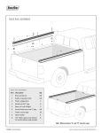
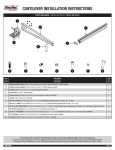
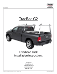
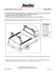
NOTES:
For good performance and safety, we recommend re-torquing all clamps and fasteners to the proper specifications after the first 500
miles and every 5000 miles thereafter.
Carrying high loads over rough roads with excess speed may damage the system on your truck. Exercise good judgement at all times.
Please call us with questions or concerns: 800.501.1587 or email: [email protected]
Installation Manual
Trac Rac, Inc.
994 Jefferson Street • Fall River, MA 02721
800.501.1587
www.tracrac.com
SKU# 00-25850 Series
Contractor Rac Pro
Table 7. Upright Part Reference
4
Installation Notes:
5
• Contractor Rac Pro mounts onto the side rails of your truck without drilling.
• Installation is straight forward, and should take approximately 45 minutes to complete.
3
1. Verify that you have received the correct parts using the assembly drawing and packing list.
2
6
Figure 1. Contractor Rac Pro Installed on a truck bed.
1
UPRIGHT
Item
No.
Qty.
Part No.
Description
1
1
PI-11009
Cleat
2
2
HD-80136
Bolt 1/4-20X1.75”
3
1
FX-11139
Nut Bar
4
1
PI-23327
Spacer, Cantilever
5
2
FX-90138
Bushing, Oval Tube
6
2
HD-23163-1 Hex Flange Bolt, M8X1.25, 50mm
Figure 13. Upright Parts.
4
1
Table 8. Cantilever Clamp Part Reference
Table 1. Tools Required
1) Socket Wrench
2) 13mm, 15mm, 16mm
and 17mm Sockets
3) 5mm Allen Wrench
4) 3/16” and 5/16”
Allen Wrench
Item
No.
Qty.
Part No.
Description
1
1
01-11144
Cantilever Clamp
2
1
BL-22000-D
Label, TracRac
3
1
HD-23179
Lock Nut M10X1.5
4
4
HD-23165
Bolt, M10X1.5, 35mm Hex
Figure 14.
Cantilever
Clamp Parts.
2
3
Recommended
1) Torque Wrench
Figure 16. Tie Down Kit.
2
1
2. Install the cleat using two bolts (3/16” Allen
Wrench). Loosely attach bottom of the corner
braces to all four uprights using hex bolt
(16mm socket).
Figure 2. Cleat and Corner Brace installation.
3
1
2
UPRIGHT
Table 2. Cleat and Corner Brace Parts
Item
No.
Qty.
Part No.
Description
1
1
PI-11009
Cleat
2
2
HD-80136
Bolt 1/4-20X1.75
3
1
01-22008
Corner Brace
4
1
HD-23143-1
Hex Bolt,
M10-1.5X25
5
1
HD-23193
Heavy Washer,
M10, THICK
Contractor Rac Pro INSTRUCTION MANUAL
2
3
1
5
3
Figure 15. Forward
Bracket Parts.
Table 9. Forward Bracket Part Reference
Table 10. Tie Down Kit Part Reference
Item
No.
Qty.
Part No.
Description
Item
No.
Qty.
Part No.
Description
1
1
FX-11139
Nut Bar
1
2
10-25111
Tie Down Zinc Diecast
2
1
01-11142
Bracket, Forward
2
2
KB-90004
Knob, Female 3/8-16 UNC
3
2
HD-23163 Bolt, M8X1.25, 16mm Hex Flange
3
2
HD-80122
T-Bolt #3/8-16X1-1/8, SS
4
NOTES: Although the Contractor Rac is capable of carrying a maximum of 1250 lbs, evenly distributed between both racks,
the capability is limited to the strength of the truck sidewall it is mounted on. More information on back cover.
TracRac Inc. 994 Jefferson Street, Fall River, MA 02721-4893 • 800-501-1587
TracRac Inc. 994 Jefferson Street, Fall River, MA 02721-4893 • 800-501-1587
Contractor Rac Pro INSTRUCTION MANUAL 7
3. A
fter selecting the correct hole pattern for your truck
(using Figure 3), plug up all other holes using the black
plastic rivets. Large rivet–on the top, small rivet–on
the bottom (Figure 4).
FRONT
DODGE
FORD F150
RH
CHEVY
LH
Table 3. Plastic Rivets
TOYOTA TUNDRA
GMC
2
1
BRACKET
ASSMEBLY
2
BRACKET
ASSMEBLY
FORD F250/350
3
Figure 10. Forward Crossbar assembly.
Table 6. Forward Crossbar assembly parts
Item
No.
Qty.
Part No.
Description
1
4
HD-80218
T-Bolt, M10-1.5X25
2
2
01-25051
Bracket, Forward
3
4
HD-23179
Lock Nut #10-1.5
UPRIGHT BASE
(VERTICAL OVAL TUBE
NOT SHOWN)
10. Built forward crossbar assembly by following the steps of the
standard crossbar assembly except slide 4 bolts (item 1) into
bottom groove of the crossbar (2 per side). Attach the end caps.
Loosely attach the bracket assemblies to the crossbar using lock
nuts and 15mm socket.
11. Loosen two bolts (13mm socket) on the forward bracket assemblies.
Slide the nut bar into the cantilever groove on each side.
12C. Tighten two nuts using 15mm socket (Torque 220-240 lbs) on each side.
FRONT
CANTILEVER
CANTILEVER
GROOVE
Figure 11B. Crossbar installation. DETAIL B.
6 Contractor Rac Pro INSTRUCTION MANUAL
Description
1
15
PI-23328
Rivet, Small, Ratchet, Black
2
15
PI-23329
Rivet, Large, Ratchet, Black
4. A
ttach rubber block assembly and rubber shim to uprights
using socket head cap bolt, washer, rubber shim, rubber
block and brass square pocket nut, see Figure 4. Complete
all four upright assemblies. Do not attach the L-Rail
clamps (items 1,9 and 10), see Figure 5. NOTE: Match
the hole patterns in the rubber shims to the correct
upright. Flat surface of rubber shim must face down.
Figure 4. Front upright
assembly.
DODGE
FORD F150/250/350
LH
RH
FRONT
UPRIGHT
LH
9
Make sure that all bolts and nuts are tightened up.
Item
No.
Qty.
Part No.
Description
1
4
HD-11011
Bolt Socket Head Cap, 3/8-16x3.00”
2
2
HD-80078
3/8 Washer, THIN
3
2
RX-11031
Rubber Block
4
2
01-2100N
Sq Pocket Nut, Brass
5
1
FX-23269
Rubber Shim, Front LH
6
1
FX-23270
Rubber Shim, Front RH
7
1
FX-23271
Rubber Shim, Rear LH
(Not Shown)
8
1
FX-23272
Rubber Shim, Rear RH
(Not Shown)
Assembly is completed.
END CAP
P/N PI-23326
TWO
NUTS
Figure 12. End cap installation.
TracRac Inc. 994 Jefferson Street, Fall River, MA 02721-4893 • 800-501-1587
10
Figure 3. Footprint for base of uprights.
Table 4. Upright Assembly Parts
TWO
BOLTS
Part No.
CHEVY
GMC
12D. Press the end caps into the front and rear cantilevers.
Figure 11A. Crossbar installation. DETAIL A.
NUT
BAR
Qty.
REAR
12B. Tighten two bolts using 13mm socket (Torque 90-110 lbs).
TWO BOLTS
UPRIGHT BASE BETWEEN
THEM NOT SHOWN
TOYOTA TUNDRA
12A. Align the bracket with the end of the front cantilever.
FORWARD
BRACKET
ASSMEBLY
SNAP IN THEM TOGETHER
Item
No.
9
2
01-23222
Clamp, L-Rail
10
2
01-22911
U-Channel 3” Long
TracRac Inc. 994 Jefferson Street, Fall River, MA 02721-4893 • 800-501-1587
5
FRONT
UPRIGHT
RH
1
1
6
2
LARGE
RIVET
SMALL
RIVET
3
4
RUBBER SHIM
FLAT FACES DOWN
Contractor Rac Pro INSTRUCTION MANUAL 3
5. Insert the rubber block into the stake pocket opening and tighten up the bolt
using 5/16 Allen Wrench. Torque to 90-110 in-lbs.
EQUAL DISTANCE
EQUAL DISTANCE
6. Slide one clamp into the base of each upright. Position as shown and secure
using socket head cap bolt and U-channel. Tighten up the bolt using 5/16 Allen
Wrench. Torque to 130-150 in- lbs.
7A. Build two standard crossbar assemblies. Assemble two tie downs–items 1, 2
and 3 (See Figure 7 and Table 5). Slide them into the top groove of the crossbar.
LOCK NUT, M10X1.5
P/N HD-23179
SADDLE
SADDLE
15MM SOCKET
Figure 8. Crossbar installation.
7B. Slide 6 T-bolts (item 5) into the bottom groove of the crossbar (3 per side).
NOTE: The flat recess of the crossbar must face down.
CORNER
BRACES
7C. Attach the end caps (item 6) using screws (item 7) using 5mm Allen Wrench.
Figure 5. Upright installation.
8A. A
ttach each crossbar onto a left and right upright by inserting the T-bolts through the saddle plate and corner brace
holes. Attach 6 locknuts leaving them loose for adjustments.
Table 5. Standard Crossbar Assembly
Item
No.
Qty.
Part No.
Description
1
2
10-25111
Tiedown
2
2
KB-90004
Knob, Female 3/8-16 UNC
3
2
HD-80122
T-Bolt 3/8-16X1-1/8, SS
4
1
01-10540
Crossbar, Triple T-Slot
5
6
HD-80218
T-Bolt, M10X1.5, 25mm
6
2
PI-23325
Crossbar Endcap
7
2
HD-23276
Bolt M6X1
8B. Center the crossbar left to right. Crossbar should fit flat on the saddle plats, tighten the T-bolt nuts using 15mm socket.
Torque T-bolt nuts to 220-240 in-lbs.
BASE
9. Follow steps 1 through 6 (See Figure 9) to install the front and rear cantilevers.
2
CLAMP
SLIDE REAR CANTILEVER
(SHORT FOR SHORT BED)
ON T-SHAPE NUT BAR
Figure 6. Clamp attachment.
FRONT
CANTILEVER
6
SLIDE FRONT CANTILEVER INTO
CLAMP CENTER CLAMP AND
TIGHTEN UP FOUR BOLTS
(15mm AND 17mm SOCKETS)
THEN TIGHTEN UP TWO BOLTS
OF FRONT UPRIGHT
SLIGHTLY UNSCREW
TWO BOLTS
(13mm SOCKET)
1
TOP
FRONT
REAR
CANTILEVER
1
4
2
4
BOTTOM RECESS
SLIDE CLAMP ASSEMBLY
ON REAR CANTILEVER
7
5
6
SLIGHTLY UNSCREW TWO
BOLTS AND SLIDE
FRONT CANTILEVER ON
T-SHAPE NUT BAR
5
4
3
3
Figure 7. Standard crossbar assembly.
4 Contractor Rac Pro INSTRUCTION MANUAL
TracRac Inc. 994 Jefferson Street, Fall River, MA 02721-4893 • 800-501-1587
ALIGN REAR CANTILEVER WITH REAR UPRIGHT
AND TIGHTEN UP TWO BOLTS
TracRac Inc. 994 Jefferson Street, Fall River, MA 02721-4893 • 800-501-1587
Figure 9. Front and Rear Cantilever installation.
Contractor Rac Pro INSTRUCTION MANUAL 5