1
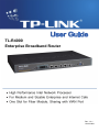
TL-R4000
Enterprise Broadband Router
Rev: 1.0.1
1910010031
COPYRIGHT & TRADEMARKS
Specifications are subject to change without notice.
is a registered trademark of
TP-LINK TECHNOLOGIES CO., LTD. Other brands and product names are trademarks or registered
trademarks of their respective holders.
No part of the specifications may be reproduced in any form or by any means or used to make any
derivative such as translation, transformation, or adaptation without permission from TP-LINK
TECHNOLOGIES CO., LTD. Copyright © 2008 TP-LINK TECHNOLOGIES CO., LTD. All rights
reserved.
http://www.tp-link.com
FCC STATEMENT
This equipment has been tested and found to comply with the limits for a Class A digital device,
pursuant to part 15 of the FCC Rules. These limits are designed to provide reasonable protection
against harmful interference when the equipment is operated in a commercial environment. This
equipment generates, uses, and can radiate radio frequency energy and, if not installed and used in
accordance with the instruction manual, may cause harmful interference to radio communications.
Operation of this equipment in a residential area is likely to cause harmful interference in which case
the user will be required to correct the interference at his own expense.
This device complies with part 15 of the FCC Rules. Operation is subject to the following two
conditions:
1) This device may not cause harmful interference.
2) This device must accept any interference received, including interference that may cause
undesired operation.
Any changes or modifications not expressly approved by the party responsible for compliance could
void the user’s authority to operate the equipment.
EC DECLARATION OF CONFORMITY (EUROPE)
In compliance with the EMC Directive 89/336/EEC, Low Voltage Directive 73/23/EEC, this product
meets the requirements of the following standards:
¾
EN55022
¾
EN55024
¾
EN60950
SAFETY NOTICES
Caution:
Do not use this product near water, for example, in a wet basement or near a swimming pool.
Avoid using this product during an electrical storm. There may be a remote risk of electric shock from
lightning.
Package Contents
The following contents should be found in your package:
¾
¾
¾
¾
One TL-R4000 Enterprise Broadband Router
One power cord for TL-R4000 Enterprise Broadband Router
Mounting kits for installing in a standard 19” rack
One Resource CD for TL-R4000 Enterprise Broadband Router, including:
•
This Guide
•
Other Helpful Information
) Note:
Make sure that the package contains the above items. If any of the listed items are damaged or
missing, please contact with your distributor.
CONTENTS
Chapter 1. Introduction....................................................................................................................1
1.1
Overview of the Router......................................................................................................1
1.2
Features ............................................................................................................................1
1.3
Panel Layout .....................................................................................................................2
1.3.1
The Front Panel......................................................................................................2
1.3.2
The Rear Panel ......................................................................................................3
Chapter 2. Connecting the Router...................................................................................................4
2.1
System Requirements .......................................................................................................4
2.2
Installation Environment Requirements .............................................................................4
2.3
Connecting the Router ......................................................................................................4
Chapter 3. Quick Installation Guide.................................................................................................5
3.1
TCP/IP configuration .........................................................................................................5
3.2
Quick Installation Guide ....................................................................................................6
Chapter 4. Configuring the Router.................................................................................................10
4.1
login.................................................................................................................................10
4.2
Status ..............................................................................................................................10
4.3
Quick Setup.....................................................................................................................11
4.4
Network ...........................................................................................................................11
4.4.1
LAN.......................................................................................................................11
4.4.2
WAN .....................................................................................................................12
4.4.3
MAC Clone ...........................................................................................................17
4.4.4
Bandwidth Control ................................................................................................18
4.4.5
VLAN ....................................................................................................................18
4.4.6
Port Mirror.............................................................................................................19
4.5
DHCP ..............................................................................................................................19
4.5.1
DHCP Settings .....................................................................................................19
4.5.2
DHCP Clients List .................................................................................................20
4.5.3
Address Reservation ............................................................................................21
4.6
Forwarding ......................................................................................................................22
4.6.1
Virtual Servers ......................................................................................................23
4.6.2
Port Triggering ......................................................................................................25
4.6.3
DMZ......................................................................................................................27
4.6.4
UPnP ....................................................................................................................27
4.7
Security ...........................................................................................................................28
4.7.1
Firewall .................................................................................................................28
4.7.2
IP Address Filtering...............................................................................................29
4.7.3
Domain Filtering ...................................................................................................31
4.7.4
MAC Filtering........................................................................................................33
4.7.5
Remote Management ...........................................................................................34
4.7.6
Advanced Security................................................................................................35
4.8
Static Routing ..................................................................................................................37
4.9
IP & MAC Binding Setting................................................................................................38
4.9.1
Binding Setting .....................................................................................................38
4.9.2
ARP List................................................................................................................40
4.10
DDNS ..............................................................................................................................41
4.10.1 Dyndns.org DDNS ................................................................................................41
4.10.2 Oray.net DDNS .....................................................................................................42
4.10.3 Comexe.cn DDNS ................................................................................................42
4.11 System Tools ...................................................................................................................44
4.11.1 Time......................................................................................................................44
4.11.2 Firmware...............................................................................................................45
4.11.3 Factory Defaults ...................................................................................................45
4.11.4 Backup & Restore Configuration ..........................................................................46
4.11.5 Reboot ..................................................................................................................46
4.11.6 Password..............................................................................................................47
4.11.7 Log .......................................................................................................................48
4.11.8 Statistics ...............................................................................................................48
Appendix A: FAQ...............................................................................................................................50
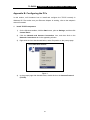
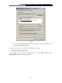
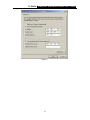
Appendix B: Configuring the PCs......................................................................................................54
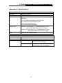
Appendix C: Specifications................................................................................................................58
Appendix D: Glossary .......................................................................................................................59
TL-R4000
Chapter 1.
1.1
Enterprise Broadband Router User Guide
Introduction
Overview of the Router
The TL-R4000 Enterprise Broadband Router possesses excellent throughput and driving
load capability, which consumedly meets the requirements from Internet café and
small/medium/sizable enterprise with volumes of users, making a more expedite
communication. The superior performance will bring you full-new experience of a
non-bottle-neck network.
TL-R4000 Enterprise Broadband Router makes plenty of applications become a reality. It
can be used for constructing intranet FTP, WEB, and Mail server, etc. Inaccessibly, it
features network game ports opened, MSN audio conversation and special application
setting, providing much more additional value to your network.
Featuring firewall and VPN Passthrough, the TL-R4000 Enterprise Broadband Router
resists most common Internet attacks and ensures secure data connectivity and
transmission over the Internet. And the expansion slot for fiber module, sharing with
WAN Port, brings an additional solution for fiber access.
TL-R4000 Enterprise Broadband Router is easy-to-manage. Quick Setup is supported
and friendly help messages are provided for every step. So you can configure it quickly
and share Internet access, files and fun comfortably.
1.2
¾
¾
¾
¾
¾
¾
¾
¾
¾
¾
¾
¾
¾
¾
¾
¾
¾
Features
Complies with IEEE802.3, IEEE802.3u standards
Built in 4-port 10/100Mbps switch
Ethernet connection to a WAN device, such as a Cable modem or DSL modem
One expansion slot for fiber module, sharing with WAN port, supports fiber access.
Shares data and Internet access for the network, connecting Internet through
PPPoE on demand and disconnecting when idle
Support Port Bandwidth Control, Port Mirror, Port-based VLAN for LAN ports
Built-in NAT and DHCP server supporting static IP address distributing
Provides 802.1x authentication for WAN port
Supports Virtual Server, Port Triggering, and DMZ host
Built-in firewall supporting IP address filtering, Domain Name filtering, and MAC
address filtering
Supports connecting/disconnecting Internet at a specified time of day
Supports access control, allowing parents and network administrators to establish
restricted access policies based on the time of day for children or staff
Supports TCP/IP, PPPoE, DHCP, ICMP, NAT, SNTP
Supports UPnP, Dynamic DNS, Static Routing, VPN pass-through
Supports Traffic Statistics
Supports ICMP-FLOOD, UDP-FLOOD, TCP-SYN-FLOOD filter
Ignores Ping packets from WAN or LAN ports
1
TL-R4000
Enterprise Broadband Router User Guide
Supports firmware upgrade
Supports Remote and Web management
Standard 19-inc rack-mountable steel case
¾
¾
¾
1.3
Panel Layout
1.3.1
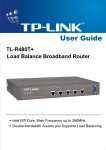
The Front Panel
The front panel of the TL-R4000 consists of several LED indicators, which is designed to
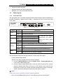
indicate connections. Viewed from left, Table 1-1 describes the LEDs on the front panel
of the router.
1
TL-R4000
2
3
4
M1
Pow er
Enterprise Broadband Router
M2
Figure 1-1 Front Panel sketch
Name
Power
M1
M2
Link/Act
Speed
Action
Description
Not lit
The router is power on
Lit up
The router is power off
Not lit
The router works properly
Lit up
The router has a hardware error
Not lit
The router has a hardware error
Lit up
The router has a hardware error
Flashing
The router works properly
Not lit
There is no device linked to the corresponding port
Lit up
There is a device linked to the corresponding port but no
activity
Flashing
There is an active device linked to the corresponding port
Not lit
The linked device is running at 10Mbps
Lit up
The linked device is running at 100Mbps
M1
and
M2
are
flashing
synchronously, the router is
restoring the factory default
settings.
Table 1-1 The LEDs description
The front panel contains the following features. (Viewed from left to right:)
¾
Factory Default Reset button
There are two ways to reset the router's factory defaults:
1.
2.
Use the Factory Defaults function on System Tools -> Factory Defaults page
in the router's Web-based Utility.
Use the Factory Default Reset button: First, turn off the router's power. Second,
press the default reset button, then turn on the router's power, and hold the
reset button until the M1 and M2 LED flash simultaneously (about 3 seconds).
At last, release the reset button and wait for the router to reboot.
) Note:
Ensure the router is powered on before it restarts completely.
¾
Four LAN 10/100Mbps RJ45 ports for connecting the router to the local PCs
2
TL-R4000
¾
¾
Enterprise Broadband Router User Guide
WAN RJ45 port for connecting the router to a cable, DSL modem or Ethernet
One expansion slot for fiber module, sharing with WAN port, the recommended
module is TL-SM21 series.
1.3.2
The Rear Panel
The rear panel of the TL-R4000 only features a power receptacle, which is an AC power
receptacle. Connect the female of the power cord head here, and the male head to the
AC power outlet.
100-240V ~ 50-60Hz
Figure 1-2 Rear Panel sketch
3
TL-R4000
Chapter 2.
2.1
¾
¾
¾
¾
¾
2.2
¾
¾
¾
¾
¾
2.3
Enterprise Broadband Router User Guide
Connecting the Router
System Requirements
Broadband Internet Access Service (DSL/Cable/Ethernet)
One DSL/Cable modem that has an RJ45 connector (It’s not necessary if you
connect the router to Ethernet)
Each PC on the LAN needs a working Ethernet Adapter and an Ethernet cable with
RJ45 connectors
TCP/IP protocol must be installed on each PC
Web browser, such as Microsoft Internet Explorer 5.0 or later, Netscape Navigator
6.0 or later
Installation Environment Requirements
Not in direct sunlight or near a heater or heating vent
Not cluttered or crowded. There should be at least 2 inches (5 cm) of clear space on
all sides of the router
Well ventilated (especially if it is in a closet)
Operating temperature: 0℃~40℃ (32℉~104℉)
Operating Humidity: 10%~90%RH, Non-condensing
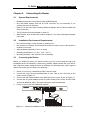
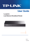
Connecting the Router
Before you install the router, you should connect your PC to the Internet through your
broadband service successfully. If there is any problem, please contact with your ISP for
help. After that, please install the router according to the following steps. Don't forget to
pull out the power plug and keep your hands dry.
1.
2.
3.
4.
5.
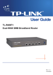
Power off your PC(s), Cable/DSL modem, and the router.
Connect the PC(s) and all Switches/Hubs on your LAN to the LAN Ports on the
router, shown in figure 3-1.
Connect the DSL/Cable modem to the WAN port on the router, shown in Figure 2-1.
Connect the AC power adapter to the AC power socket on the router, and the other
end into an electrical outlet. The router will start to work automatically.
Power on your PC(s) and Cable/DSL modem.
1
TL-R 4000
E n te rp ri se Bro a d ba n d Ro u te r
2
3
4
M1
Power
M2
To WAN
To LAN
Switch/Hub
(XDSL、 Cable、 Ethernet)
Figure 2-1
Hardware Installation of the TL-R4000 Enterprise Broadband Router
4
TL-R4000
Chapter 3.
Enterprise Broadband Router User Guide
Quick Installation Guide
After connecting the TL-R4000 router into your network, you should configure it. This
chapter describes how to configure the basic functions of your TL-R4000 Enterprise
Broadband Router. These procedures only take you a few minutes. You can access the
Internet via the router immediately after it has been successfully configured.
3.1 TCP/IP configuration
The default IP address of the TL-R4000 Enterprise Broadband Router is 192.168.1.1,
and the default Subnet Mask is 255.255.255.0. These values can be seen from the LAN,
and can be changed as your desire. As an example, we use the default values for
description in this guide.
Connect the local PCs to the LAN ports on the router. There are then two means to
configure the IP address for your PCs.
¾
Configure the IP address manually
1)
Set up the TCP/IP Protocol for your PC. If you need instructions as to how to do
this, please refer to Appendix B: "Configuring the PC."
2)
Configure the network parameters. The IP address is 192.168.1.xxx ("xxx" is
any number from 2 to 254), Subnet Mask is 255.255.255.0, and Gateway is
192.168.1.1 (The router's default IP address)
¾
Obtain an IP address automatically
1)
Set up the TCP/IP Protocol in "Obtain an IP address automatically" mode on
your PC. If you need instructions as to how to do this, please refer to Appendix
B: "Configuring the PC."
2)
Then the built-in DHCP server will assign IP address for the PC.
) Note:
For Windows 98 OS or earlier, the PC and router may need to be restarted.
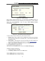
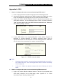
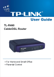
Now, you can run the Ping command in the command prompt to verify the network
connection between your PC(s) and the router. The following example is in Windows
2000.
Open a command prompt, and type ping 192.168.1.1, then press Enter.
5
TL-R4000
Figure 3-1
Enterprise Broadband Router User Guide
Successful result of Ping command
If the result displayed is similar to what is shown in Figure 3-1, the connection between
your PC and the router has been established.
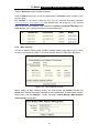
Figure 3-2
Failed result of Ping command
If the result displayed is similar to what shown in Figure 3-2, it means that your PC has
not connected to the router. If so, refer to the following steps for a solution.
1.
Is the connection between your PC and the router correct?
) Note:
The Link/Act LEDs of LAN port on the router and LEDs on your PC's adapter should be
lit.
2. Is the TCP/IP configuration for your PC correct?
) Note:
If the router's IP address is 192.168.1.1, your PC's IP address must be within the range
of 192.168.1.2 ~ 192.168.1.254.
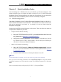
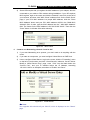
3.2 Quick Installation Guide
With a Web-based (Internet Explorer or Netscape® Navigator) utility, the TL-R4000
Enterprise Broadband Router is easy to configure and manage. The Web-based utility
can be used on any Windows, Macintosh or UNIX OS with a web browser.
Connect to the router by typing http://192.168.1.1 in the address field of web browser.
Figure 3-3
Login to the router
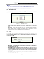
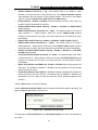
After a moment, a login window will appear similar to that shown in Figure 3-4. Enter
6
TL-R4000
Enterprise Broadband Router User Guide
admin for the User Name and Password, both in lower case letters. Then click the OK
button or press the Enter key.
Figure 3-4
Login Windows
) Note:
If the above screen does not prompt, it means that your web-browser has been set to a
proxy. Go to Tools menu>Internet Options>Connections>LAN Settings, in the screen that
appears, cancel the Using Proxy checkbox, and click OK to finish it.
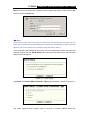
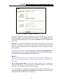
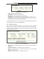
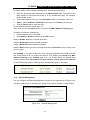
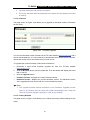
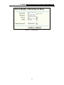
If the User Name and Password are correct, you can configure the router using the web
browser. Please click the Quick Setup link on the left of the main menu and the Quick
Setup screen will appear.
Figure 3-5
Quick Setup
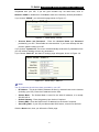
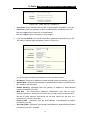
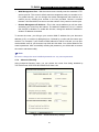
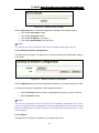
Click Next, the Choose WAN Connection Type page will appear, shown in Figure 3-6.
Figure 3-6
Choose WAN Connection Type
The router supports three popular ways to connect to Internet. Please select one
7
TL-R4000
Enterprise Broadband Router User Guide
compatible with your ISP, if you are given another way not listed here, refer to
Network->WAN for detailed list. Click Next to enter the necessary network parameters.
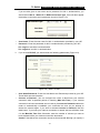
If you choose "PPPoE", you will see this page shown in Figure 3-7:
Figure 3-7
¾
Quick Setup - PPPoE
Account Name and Password - Enter the Account Name and Password
provided by your ISP. These fields are case sensitive. If you have difficulty with this
process, please contact your ISP.
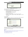
If you choose " Dynamic IP", the router will automatically receive the IP parameters from
your ISP without needing to enter any parameters.
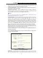
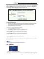
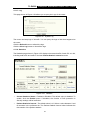
If you Choose "Static IP", the Static IP settings page will appear, shown in Figure 3-8:
Figure 3-8
Quick Setup - Static IP
) Note:
The IP parameters should have been provided by your ISP.
¾
IP Address - This is the WAN IP address as seen by external users on the Internet
(including your ISP). Enter the IP address into the field.
¾
Subnet Mask - The Subnet Mask is used for the WAN IP address, it is usually
255.255.255.0.
¾
Default Gateway - Enter the gateway into the box if required.
Primary DNS - Enter the DNS Server IP address into the boxes if required.
Secondary DNS - If your ISP provides another DNS server, enter it into this field.
¾
¾
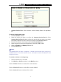
Click the Next button, then you will see the Finish page:
8
TL-R4000
Enterprise Broadband Router User Guide
Figure 3-9
Quick Setup - Finish
After finishing all configurations of basic network parameters, please click Finish button
to exit this Quick Setup.
9
TL-R4000
Chapter 4.
Enterprise Broadband Router User Guide
Configuring the Router
This chapter describes each web page's key functions.
4.1 login
After your successful login, you can configure and manage the router. There are nine main
menus on the left of the web-based utility. Submenus will be available after you click one
of the main menus. The ten main menus are: Status, Quick Setup, Network, DHCP,
Forwarding, Security, Static Routing, IP & MAC Binding, Dynamic DNS, and System
Tools. On the right of the web-based utility, there are the detailed explanations and
instructions for the corresponding page. To apply any settings you have altered on the
page, please click the Save button.
There are the detailed explanations for each web page's key functions below.
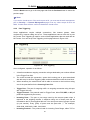
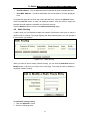
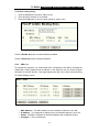
4.2 Status
The Status page displays the router's current status and configuration. All information is
read-only.
1.
LAN
This field displays the current settings or information for the LAN, including the MAC
address, IP address and Subnet Mask.
2.
WAN
These parameters apply to the WAN port of the router, including MAC address, IP
address, Subnet Mask, Default Gateway, DNS server and WAN connection type.
If PPPoE is chosen as the WAN connection type, the Disconnect button will be
shown here while you are accessing the Internet. You can also cut the connection by
clicking the button. If you have not connected to the Internet, a Connect button will be
shown, you can then establish the connection by clicking the button.
3.
Traffic Statistics
This field displays the router's traffic statistics.
4.
System Up Time
The time of the router running from the time it is powered on or is reset.
10
TL-R4000
Enterprise Broadband Router User Guide
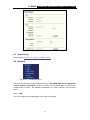
Figure 4-1
Router Status
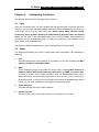
4.3 Quick Setup
Please refer to Section 3.2: "Quick Installation Guide."
4.4 Network
Figure 4-2
the Network menu
There are six submenus under the Network menu: LAN, WAN, MAC Clone, Bandwidth
Control, VLAN and Port Mirror. Click any of them, and you will be able to configure the
corresponding function. The detailed explanations for each submenu are provided
below.
4.4.1
LAN
You can configure the IP parameters of the LAN on this page.
11
TL-R4000
Enterprise Broadband Router User Guide
Figure 4-3
LAN
¾
MAC Address - The physical address of the router, as seen from the LAN. The
value can't be changed.
¾
IP Address - Enter the IP address of your router in dotted-decimal notation (factory
default: 192.168.1.1).
¾
Subnet Mask - An address code that determines the size of the network. Normally
use 255.255.255.0 as the subnet mask.
) Note:
a.
b.
c.
If you change the IP address of the LAN, you must use the new IP address to login
to the router.
If the new LAN IP Address you set is not in the same subnet, the IP Address pool of
the DHCP sever will not take effect, until it is re-configured.
If the new LAN IP Address you set is not in the same subnet, the Virtual Server and
DMZ Host may change accordingly at the same time, you’d better re-configure it as
well.
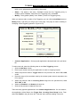
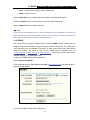
4.4.2
WAN
You can configure the WAN port parameters on this page.
First, please choose the WAN Connection Type (Dynamic IP/Static IP/PPPoE/802.1x +
Dynamic IP/802.1x + Static IP) to the Internet. The default type is PPPoE. If you aren’t
given any login parameters (fixed IP address, logging ID, etc), please select Dynamic
IP. If you are given a fixed IP (static IP), please select Static IP. If you are given a user
name and a password, please select PPPoE. If you are not sure which connection type
you use currently, please contact your ISP to obtain the correct information.
1.
If you choose Dynamic IP, the router will automatically get IP parameters from
your ISP. You can see the page as follows :
12
TL-R4000
Enterprise Broadband Router User Guide
Figure 4-4
WAN - Dynamic IP
This page displays the WAN IP parameters assigned dynamically by your ISP,
including IP address, Subnet Mask, Default Gateway, etc. Click the Renew button to
renew the IP parameters from your ISP. Click the Release button to release the IP
parameters.
MTU Size: The normal MTU (Maximum Transmission Unit) value for most Ethernet
networks is 1500 Bytes. For some ISPs you need to reduce the MTU. But this is
rarely required, and should not be done unless you are sure it is necessary for your
ISP connection.
If your ISP gives you one or two DNS addresses, select Use These DNS Servers
and enter the primary and secondary addresses into the correct fields. Otherwise,
the DNS servers will be assigned dynamically from ISP.
) Note:
If you get ‘Address not found' errors when you go to a Web site, it is likely that your
DNS servers are set up improperly. You should contact your ISP to get DNS server
addresses.
Get IP with Unicast DHCP: A few ISPs' DHCP servers do not support the
broadcast applications. If you cannot get the IP address normally, you can choose
this option. (You generally need not check this option).
If you are also given a user name and a password for 802.1x authentication, you
should select 802.1x + Dynamic IP for WAN Connection Type, a user name and a
password will then appear, shown in Figure 4-5a:
13
TL-R4000
Figure 4-5a
¾
¾
2.
Enterprise Broadband Router User Guide
WAN - 802.1X + Dynamic IP
User Name - Enter the user name for 802.1x authentication provided by your ISP
Password - Enter the password for 802.1x authentication provided by your ISP.
Click the Login button to start 802.1x authentication.
Click the Logout button to end 802.1x authentication.
If you choose Static IP, you should have fixed IP parameters specified by your ISP.
The Static IP settings page will appear, shown in Figure 4-6:
Figure 4-6
WAN - Static IP
You should type the following parameters into the spaces provided:
¾
¾
IP Address - Enter the IP address in dotted-decimal notation provided by your ISP.
Subnet Mask - Enter the subnet Mask in dotted-decimal notation provided by your
ISP, usually is 255.255.255.0.
¾
Default Gateway: (Optional) Enter the gateway IP address in dotted-decimal
notation provided by your ISP.
¾
MTU Size - The normal MTU (Maximum Transmission Unit) value for most
Ethernet networks is 1500 Bytes. For some ISPs you may need to modify the MTU.
But this is rarely required, and should not be done unless you are sure it is
necessary for your ISP connection.
¾
Primary DNS - (Optional) Type the DNS address in dotted-decimal notation
provided by your ISP.
¾
Secondary DNS - (Optional) Type another DNS address in dotted-decimal notation
provided by your ISP if provided.
14
TL-R4000
Enterprise Broadband Router User Guide
If you are also given a user name and a password for 802.1x authentication, you
should select 802.1x + Static IP for WAN Connection Type, a box will then appear
requesting a user name and a password, shown in Figure 4-7a:
Figure 4-7a
¾
¾
3.
WAN - 802.1X + Static IP
User Name - Enter the user name for 802.1x authentication provided by your ISP
Password - Enter the password for 802.1x authentication provided by your ISP.
Click Login to start 802.1x authentication.
Click Logout to end 802.1x authentication.
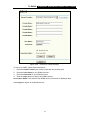
If you choose PPPoE, you should enter the following parameters (Figure 4-8):
Figure 4-8
WAN - PPPoE
¾
User Name/Password - Enter the User Name and Password provided by your ISP.
These fields are case-sensitive.
¾
Connect on Demand - You can configure the router to disconnect your Internet
connection after a specified period of inactivity (Max Idle Time). If your Internet
connection has been terminated due to inactivity, Connect on Demand enables the
router to automatically re-establish your connection as soon as you attempt to
access the Internet again. If you wish to activate Connect on Demand, click the
radio button. If you want your Internet connection to remain active at all times, enter
0 in the Max Idle Time field. Otherwise, enter the number of minutes you want to
have elapsed before your Internet connection terminates.
Caution: Sometimes the connection cannot be disconnected although you specify a
15
TL-R4000
Enterprise Broadband Router User Guide
time to Max Idle Time. This is because there may still be active applications in the
background, which may cause fee accounted by your ISP.
¾
Connect Automatically - Connect automatically after the router is disconnected. To
use this option, click the radio button.
¾
Time-based Connecting - You can configure the router to make it connect or
disconnect based on time. Enter the start time in HH:MM for connecting and end
time in HH:MM for disconnecting in the Period of Time fields.
) Note:
Only you have set the system time on System Tools -> Time page, will the
Time-based Connecting function take effect.
¾
Connect Manually - You can configure the router to make it connect or disconnect
manually. After a specified period of inactivity (Max Idle Time), the router will
disconnect your Internet connection, and not be able to re-establish your connection
automatically as soon as you attempt to access the Internet again. To use this option,
click the radio button. If you want your Internet connection to remain active at all
times, enter 0 in the Max Idle Time field. Otherwise, enter the number in minutes
that you wish to have the Internet connecting last unless a new link is requested.
Caution: Sometimes the connection cannot be disconnected although you specify a
time to Max Idle Time. This is because there may still be active applications in the
background, which may cause fee accounted by your ISP.
Click the Connect button to connect immediately, Click the Disconnect button to
disconnect immediately.
Click the Advanced Settings button to set up the advanced option, the page shown
in Figure 4-9 will then appear:
Figure 4-9
¾
PPPoE Advanced Settings
Packet MTU - The default MTU size is 1492 bytes, which is usually fine. For some
ISPs, you need modify the MTU. This should not be done unless you are sure it is
16
TL-R4000
Enterprise Broadband Router User Guide
necessary for your ISP.
¾
Service Name/AC Name - The service name and AC (Access Concentrator) name,
this should not be done unless you are sure it is necessary for your ISP.
¾
ISP Specified IP Address - If you know that your ISP does not automatically
transmit your IP address to the router during login, click “Use the IP Address
specified by ISP” check box and enter the IP address in dotted-decimal notation,
which your ISP provided.
¾
Detect Online Interval - The default value is 0, you can input the value between 0
and 120. The router will detect Access Concentrator online at every interval between
seconds. If the value is 0, it means do not detect.
¾
DNS IP Address - If you know that your ISP does not automatically transmit DNS
addresses to the router during login, click “Use the following DNS servers”
checkbox and enter the IP address in dotted-decimal notation of your ISP’s primary
DNS server. If a secondary DNS server address is available, enter it as well.
Click the Save button to save your settings.
4.4.3
MAC Clone
You can configure the MAC address of the WAN port on this page, Figure 4-10:
Figure 4-10 MAC Address Clone
Some ISPs require that you register the MAC address of your adapter, which is
connected to your cable, DSL modem or Ethernet during installation. You do not
generally need to change anything here.
¾
WAN MAC Address - This field displays the current MAC address of the WAN port,
which is used for the WAN port. If your ISP requires that you register the MAC
address, please enter the correct MAC address into this field. The format for the
MAC address is XX-XX-XX-XX-XX-XX (X is any hexadecimal digit).
¾
Your PC's MAC Address - This field displays the MAC address of the PC that is
managing the router. If the MAC address is required, you can click the Clone MAC
Address button and this MAC address will fill in the WAN MAC Address field.
Click Restore Factory MAC to restore the MAC address of WAN port to the factory
default value.
Click the Save button to save your settings.
17
TL-R4000
Enterprise Broadband Router User Guide
) Note:
1)
2)
4.4.4
Only the PC(s) on your LAN can use the MAC Address Clone feature.
If you click the Save button, the router will prompt you to reboot.
Bandwidth Control
You can control bandwidth of each LAN port on this page. This feature can be used for
distributing flexibly Internet resource.
Figure 4-11
Bandwidth Control
¾
LAN - LAN port number. LAN1 point to LAN port 1, LAN2 point to LAN port 2, and
so on.
¾
Bandwidth - Select the bandwidth value from 128Kbps, 256Kbps, 512Kbps,
1Mbps, 2Mbps, 4Mbps and 8Mbps. The selected value is the maximum Internet
bandwidth for the LAN port. No-limit means no bandwidth limit.
4.4.5
VLAN
On this page, you can configure VLAN based on LAN port. There are three VLAN
modes in the VLAN Mode pull-down list: One VLAN, Two VLAN and Four VLAN, the
default is One VLAN.
Figure 4-12
VLAN Settings
¾
One VLAN - In this VLAN mode, all LAN ports are in one VLAN, all LAN ports can
communicate with each other.
¾
Two VLANs - In this VLAN mode, the LAN1 and LAN2 are in one VLAN, and the
LAN3 and LAN4 are in another VLAN. So LAN1 can communicate with LAN2 and
LAN3 can communicate with LAN4, but LAN1 or LAN2 cannot communicate with
LAN3 or LAN4.
¾
Four VLANs - In this VLAN mode, all ports are in different VLANs. So they cannot
communicate with each other.
18
TL-R4000
4.4.6
Enterprise Broadband Router User Guide
Port Mirror
You can configure LAN port mirror feature on this page.
Figure 4-13
¾
¾
Port Mirror
Mirror Port - The port will collect packet from Mirrored Port(s).
Mirrored Port(s) - Any packets through the Mirrored Port(s) will be copied and be
forwarded to the Mirror Port.
) Note:
1) The Mirror port cannot be mirrored.
2) All in the Mirrored Port(s) means all LAN ports except for Mirror Port.
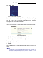
4.5 DHCP
Figure 4-14
the DHCP menu
There are three submenus under the DHCP menu: DHCP Settings, DHCP Clients List
and Address Reservation. Click any of them, and you will be able to configure the
corresponding function. The detailed explanations for each submenu are provided
below.
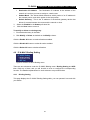
4.5.1
DHCP Settings
The router is set up by default as a DHCP (Dynamic Host Configuration Protocol) server,
which provides the TCP/IP configuration for all the PCs that are connected to the router
on the LAN. The DHCP Server can be configured on the page:
19
TL-R4000
Enterprise Broadband Router User Guide
Figure 4-15
DHCP Settings
¾
DHCP Server - Enable or Disable the DHCP server. If you disable the Server, you
must have another DHCP server within your network or else you must manually
configure the computer.
¾
Start IP Address - This field specifies the first of the addresses in the IP address
pool. 192.168.1.100 is the default start address.
¾
End IP Address - This field specifies the last of the addresses in the IP address
pool. 192.168.1.199 is the default end address.
¾
Address Lease Time - The Address Lease Time is the amount of time a network
user will be allowed connection to the router with their current dynamic IP address.
Enter the amount of time, in minutes, which the user will be "leased" this dynamic
IP address. The range of the time is 1 ~ 2880 minutes. The default value is 120
minutes.
¾
Default Gateway - (Optional.) Suggest to input the IP address of the LAN port of
the router, default value is 192.168.1.1
¾
Default Domain - (Optional.) Input the domain name of your network.
Primary DNS - (Optional.) Input the DNS IP address provided by your ISP. Or
consult your ISP.
¾
¾
Secondary DNS - (Optional.) Input the IP address of another DNS server if your
ISP provides two DNS servers.
) Note:
To use the DHCP server function of the router, you must configure all computers on the
LAN as "Obtain an IP Address automatically" mode. This function will take effect until the
router reboots.
4.5.2
DHCP Clients List
This page shows Client Name, MAC Address, Assigned IP and Lease Time for each
DHCP Client attached to the router:
20
TL-R4000
Enterprise Broadband Router User Guide
Figure 4-16
¾
¾
¾
¾
¾
DHCP Clients List
Index - The index of the DHCP Client
Client Name - The name of the DHCP client
MAC Address - The MAC address of the DHCP client
Assigned IP - The IP address that the router has allocated to the DHCP client.
Lease Time - The time of the DHCP client leased. Before the time is up, DHCP
client will request to renew the lease automatically.
You cannot change any of the values on this page. To update this page and to show the
current attached devices, click on the Refresh button.
4.5.3
Address Reservation
When you specify a reserved IP address for a PC on the LAN, that PC will always
receive the same IP address each time it accesses the DHCP server. Reserved IP
addresses should be assigned to servers that require permanent IP settings. This page
is used for address reservation.
Figure 4-17
Address Reservation
¾
MAC Address - The MAC address of the PC of which you want to reserve IP
address.
¾
¾
Reserved IP Address - The IP address of the router reserved.
Status - The status of the entry, "Enabled" means the entry is valid, ”Disable”
means the entry is invalid.
¾
Modify - The hyperlink (Modify” and “Delete”) of the entry.
21
TL-R4000
Enterprise Broadband Router User Guide
When you want to add or modify a Address Reservation, you can click the Add New
button or Modify button, then you will go to the next page. This page is used for adding
or modifying a Address Reservation (shown in Figure 4-18).
Figure 4-18
Add or Modify a Address Reseration Entry
To Reserve IP addresses:
1. Enter the MAC address (The format for the MAC address is XX-XX-XX-XX-XX-XX.)
and IP address in dotted-decimal notation of the computer you wish to add.
2.
Click the Save button when finished.
To modify or delete a Reserved IP address:
1. Find the desired entry in the table.
2.
Click Modify or Delete as desired on the Modify column.
Click the Enable All button to make all the entries enabled.
Click the Disable All button to make all the entries disabled.
Click the Delete All button to delete all the entries.
Click the Next button to go to the next page and Click the Previous button to return to
the previous page.
) Note:
The function won't take effect until the router reboots.
4.6 Forwarding
Figure 4-19
the Forwarding menu
There are four submenus under the Forwarding menu: Virtual Servers, Port Triggering,
22
TL-R4000
Enterprise Broadband Router User Guide
DMZ and UPnP. Click any of them, and you will be able to configure the corresponding
function. The detailed explanations for each submenu are provided below.
4.6.1
Virtual Servers
Virtual servers can be used for setting up public services on your LAN, such as DNS,
Email and FTP. A virtual server is defined as a service port, and all requests from
Internet to this service port will be redirected to the computer specified by the server IP.
Any PC that was used for a virtual server must have a static or reserved IP address
because its IP address may change when using the DHCP function. You can set up
virtual servers on this page, shown in Figure 4-20:
Figure 4-20
Virtual Servers
¾
Service Port - The numbers of External Ports. You can type a service port or a
range of service ports (the format is XXX – YYY, XXX is Start port, YYY is End
port).
¾
IP Address - The IP address of the PC running the service application
Protocol - The protocol used for this application, either TCP, UDP, or All (all
protocols supported by the router).
¾
¾
Status - The status of this entry, "Enabled" means the virtual server entry is
enabled, while “Disabled” means the virtual server entry is disabled.
¾
Modify - The hyperlink (“Modify” and “Delete”) of the entry.
When you want to add or modify a Virtual server, you can click the Add New button or
Modify button, and then you will go to the next page. This page is used for adding or
modifying an Address Reservation (shown in Figure 4-21).
23
TL-R4000
Figure 4-21
¾
Enterprise Broadband Router User Guide
Add or Modify a Virtual Server Entry
Common Service Port - Some common services already listed in the pull-down
list.
To setup a virtual server entry:
1. Click the Add New.. button.
2. Select the service you want to use from the Common Service Port list, If the
Common Service Port list does not have the service that you want to use, enter
the number of the service port or service port range in the Service Port box.
3. Enter the IP address of the computer in the Server IP Address box.
4. Select the protocol used for this application, either TCP, UDP, or All.
5. Select the Enable in the Status pull-down list.
6. Click the Save button.
) Note:
It is possible that you have a computer or server that has more than one type of
available service. If so, select another service, and enter the same IP address for that
computer or server.
To modify or delete an existing entry:
1.
Find the desired entry in the table.
2.
Click Modify or Delete as desired on the Modify column.
Click the Enable All button to make all the entries enabled.
Click the Disable All button to make all the entries disabled.
Click the Delete All button to delete all the entries.
24
TL-R4000
Enterprise Broadband Router User Guide
Click the Next button to go to the next page and Click the Previous button to return the
previous page.
) Note:
If you set the virtual server of the service port as 80, you must set the web management
port on Security –> Remote Management page to be any value except 80 such as
8080. Or else there will be a conflict to disable the virtual server.
4.6.2
Port Triggering
Some applications require multiple connections, like Internet games, video
conferencing, Internet calling and so on. These applications cannot work with a pure
NAT router. Port Triggering is used for some of these applications that can work with an
NAT router. You can set up Port Triggering on this page shown in Figure 4-22:
Figure 4-22
Port Triggering
Once configured, operation is as follows:
1.
2.
3.
A local host makes an outgoing connection using a destination port number defined
in the Trigger Port field.
The router records this connection, opens the incoming port or ports associated
with this entry in the Port Triggering table, and associates them with the local host.
When necessary the external host will be able to connect to the local host using
one of the ports defined in the Incoming Ports field.
¾
Trigger Port - The port for outgoing traffic. An outgoing connection using this port
will "Trigger" this rule.
¾
Trigger Protocol - The protocol used for Trigger Ports, either TCP,UDP, or All (all
protocols supported by the router).
¾
Incoming Ports - The port or port range used by the remote system when it
responds to the outgoing request. A response using one of these ports will be
forwarded to the PC that triggered this rule. You can input at most 5 groups of ports
(or port section). Every group of ports must be apart with ",". For example,
2000-2038, 2050-2051, 2085, 3010-3030.
¾
Incoming Protocol - The protocol used for Incoming Ports Range, either TCP or
25
TL-R4000
Enterprise Broadband Router User Guide
UDP, or ALL (all protocols supported by the router).
¾
Status - The status of this entry, "Enabled" means the Port Triggering entry is
enabled, while “Disabled” means the Port Triggering entry is disabled.
¾
Modify - The hyperlink (Modify” and “Delete”) of the Port Triggering entry.
When you want to add or modify a Port Triggering, you can click the Add New button or
Modify button, and then you will go to the next page. This page is used for adding or
modifying a Port Triggering (shown in Figure 4-23).
Figure 4-23
¾
Add or Modify a Port Triggering Entry
Common Applications - Some popular applications already listed in the pull-down
list.
To add a new rule, enter the following data on the Port Triggering screen.
1. Click the Add New.. button.
2. Enter a port number used by the application to send an outgoing request.
3.
4.
5.
6.
7.
Select the protocol used for Trigger Port from the pull-down list, either TCP, UDP,
or All.
Enter the range of port numbers used by the remote system when it responds to the
PC's request.
Select the protocol used for Incoming Ports range from the pull-down list, either
TCP, UDP, or All.
Select the Enabled in the Status pull-down list.
Click the Save button to save the new rule.
There are many popular applications in the Common Application list. You can select it,
the application will be filled in the Trigger Port, incoming Ports Range boxes. Then
select the Enable in the pull-down list. It has the same effect as adding a new rule.
26
TL-R4000
Enterprise Broadband Router User Guide
To modify or delete an existing entry:
1.
Find the desired entry in the table.
2.
Click Modify or Delete as desired on the Modify column.
3.
Click the Enable All button to make all the entries enabled.
4.
Click the Disable All button to make all the entries enabled.
5.
Click the Delete All button to delete all the entries.
6.
Click the Next button to go to the next page and Click the Previous button to return
to the previous page.
) Note:
1. When the trigger connection is released, the according opening ports will be closed.
2. Each rule allowed to be used only by one host on LAN synchronously. The trigger
connection of other hosts on LAN will be refused.
3.
Incoming Ports range cannot overlap each other.
4.6.3
DMZ
The DMZ host feature allows one local host to be exposed to the Internet for a
special-purpose service such as Internet gaming or videoconferencing. DMZ host
forwards all the ports at the same time. Any PC whose port is being forwarded must have
its DHCP client function disabled and should have a new static IP address assigned to it
because its IP address may change when using the DHCP function. You can set up DMZ
host on this page shown in Figure 4-24:
Figure 4-24
DMZ
To assign a computer or server to be a DMZ server:
1.
2.
3.
Click the Enable radio button
Enter the local host IP address in the DMZ Host IP Address field
Click the Save button.
) Note:
After you set the DMZ host, the firewall related to the host will not work.
4.6.4
UPnP
The Universal Plug and Play (UPnP) feature allows the devices, such as Internet
computers, to access the local host resources or devices as needed. UPnP devices can
27
TL-R4000
Enterprise Broadband Router User Guide
be automatically discovered by the UPnP service application on the LAN. You can
configure UPnP on this page shown in Figure 4-25:
Figure 4-25
UPnP Settings
¾
Enable UPnP - UPnP can be enabled or disabled by clicking the Enable or
Disable button. As allowing this may present a risk to security, this feature is
disabled by default.
¾
Current UPnP Settings Table - this table displays the current UPnP information.
•
App Description – The description provided by the application in the UPnP
request
•
•
•
•
•
External Port - External port, which the router opened for the application.
Protocol - Which type of protocol is opened.
Internal Port - Internal port, which the router opened for local host.
IP Address - The UPnP device that is currently accessing the router.
Status - Either Enabled or Disabled, “Enabled” means that port is still active,
otherwise, the port is inactive.
Click Refresh to update the Current UPnP Settings List.
4.7 Security
Figure 4-26
the Security menu
There are six submenus under the Security menu: Firewall, IP Address Filtering,
Domain Filtering, MAC Filtering, Remote Management and Advanced Security.
Click any of them, and you will be able to configure the corresponding function. The
detailed explanations for each submenu are provided below.
4.7.1
Firewall
Using the Firewall page (shown in Figure 4-27), you can turn the general firewall switch
28
TL-R4000
Enterprise Broadband Router User Guide
on or off. The default setting for the switch is off. If the general firewall switch is off, even
if IP Address Filtering, DNS Filtering and MAC Filtering are enabled, their settings are
ineffective.
Figure 4-27
¾
¾
¾
¾
Firewall Settings
Enable Firewall - The general firewall switch is on or off.
Enable IP Address Filtering - Set IP Address Filtering is enabled or disabled.
There are two default filtering rules of IP Address Filtering, either Allow or Reny
passing through the router.
Enable Domain Filtering - Set Domain Filtering as enabled or disabled.
Enable MAC Filtering - Set MAC Address Filtering is enabled or disabled. You can
select the default filtering rules of MAC Address Filtering, either Allow or Reny
accessing the router.
4.7.2
IP Address Filtering
The IP Address Filtering feature allows you to control Internet Access by specific users
on your LAN based on their IP addresses. The IP Address Filtering are set on this page,
Figure 4-28:
29
TL-R4000
Enterprise Broadband Router User Guide
Figure 4-28
IP Address Filtering
To disable the IP Address Filtering feature, keep the default setting, Disabled. To set up
an IP Address Filtering entry, click Enable Firewall and Enable IP Address Filtering on
the Firewall page, and click the Add New… button. The page " Add or Modify an IP
Address Filtering entry " will appear shown in Figure 4-29:
Figure 4-29
Add or Modify an IP Address Filtering Entry
To create or modify an IP Address Filtering entry, please follow these instructions:
1.
Effective Time - Enter a range of time in HHMM format, which point to the range
time for the entry to take effect. For example, 0803 - 1705, the entry will take effect
from 08:03 to 17:05.
2.
LAN IP Address - Type a LAN IP address or a range of LAN IP addresses in the
field, in dotted-decimal notation format. For example, 192.168.1.20 - 192.168.1.30.
Keep the field open, which means all LAN IP addresses have been put into the field.
3.
LAN Port - Type a LAN Port or a range of LAN ports in the field. For example, 1030
- 2000. Keep the field open, which means all LAN ports have been put into the field.
4.
WAN IP Address - Type a WAN IP address or a range of WAN IP addresses in the
field, in dotted-decimal notation format. For example, 61.145.238.6 – 61.145.238.47.
Keep the field open, which means all WAN IP addresses have been put into the
field.
5.
WAN Port - Type a WAN Port or a range of WAN Ports in the field. For example, 25
30
TL-R4000
Enterprise Broadband Router User Guide
– 110. Keep the field open, which means all WAN Ports have been put into the field.
6.
Protocol - Select which protocol is to be used, either TCP, UDP, or All (all protocols
supported by the router).
7. Pass - Select either Allow or Deny through the router.
8. Status - Select Enabled or Disabled for this entry on the Status pull-down list.
9. Click the Save button to save this entry.
To add additional entries, repeat steps 1-9.
When finished, click the Return button to return to IP Address Filtering page.
To modify or delete an existing entry:
1. Find the desired entry in the table.
2.
Click Modify or Delete as desired on the Modify column.
Click the Enable All button to enable all entries.
Click the Disable All button to disable all entries.
Click the Delete All button to delete all entries
You can change the entry’s order as desired. Fore entries are before hind entries. Enter
the ID number in the first box you want to move and another ID number in the second
box you want to move to, and then click the Move button to change the entry’s order.
Click the Next button to go to the next page and click the Previous button to return to the
previous page.
For example: If you desire to block E-mail received and sent by the IP address
192.168.1.7 on your local network, and wish to make the PC with IP address 192.168.1.8
unable to visit the website of IP address 202.96.134.12, while other PCs have no limit.
First, enable the Firewall and IP Address Filtering on the Firewall page, then, you
should specify the Default IP Address Filtering Rule "Deny these PCs with effective
rules to access the Internet" on the Firewall page and the following IP address filtering
list on this page:
4.7.3
Domain Filtering
The Domain Filtering page allows you to control access to certain websites on the
Internet by specifying their domains or key words.
31
TL-R4000
Enterprise Broadband Router User Guide
Figure 4-30
Domain Filtering
Before adding a Domain Filtering entry, you must ensure that Enable Firewall and
Enable Domain Filtering have been selected on the Firewall page. To Add a Domain
filtering entry, click the Add New… button. The page " Add or Modify a Domain
Filtering entry " will appear:
Figure 4-31
Add or Modify a Domain Filtering entry
To add or modify a Domain Filtering entry, follow these instructions:
1.
Effective Time - Enter a range of time in HHMM format, which point to the range
time for the entry to take effect. For example, 0803 - 1705, the entry will take effect
from 08:03 to 17:05.
2.
Domain Name - Type the domain or key word as desired in the field. A blank in the
domain field means all websites on the Internet. For example: www.xxyy.com.cn.
3. Status - Select Enabled or Disabled for this entry on the Status pull-down list.
4. Click the Save button to save this entry.
To add additional entries, repeat steps 1-4.
When finished, click the Return button to return to the Domain filtering page.
To Modify or delete an existing entry:
1. Find the desired entry in the table.
2.
Click Modify or Delete as desired on the Edit column.
Click the Enable All button to enable all entries.
Click the Disable All button to disable all entries.
32
TL-R4000
Enterprise Broadband Router User Guide
Click the Delete All button to delete all entries
Click the Next button to go to the next page and the Previous button to return to the
previous page.
For example: if you want to block the PCs on your LAN from accessing websites
www.xxyy.com.cn, www.aabbcc.com and websites with .net at the end on the Internet
while no limit for other websites. First, enable the Firewall and Domain Filtering on the
Firewall page, then, specify the following Domain filtering list:
4.7.4
MAC Filtering
Like the IP Address Filtering page, the MAC Address Filtering page allows you to control
access to the Internet by users on your local network based on their MAC addresses.
Figure 4-32
MAC Address Filtering
Before setting up MAC Filtering entries, you must ensure that Enable Firewall and
Enable MAC Filtering have been selected on the Firewall page. To Add a MAC Address
filtering entry, click the Add New… button. The page " Add or Modify a MAC Address
Filtering entry" will appear:
Figure 4-33
Add or Modify a MAC Address Filtering entry
33
TL-R4000
Enterprise Broadband Router User Guide
To add or modify a MAC Address Filtering entry, follow these instructions:
1.
Enter the appropriate MAC address into the MAC Address field. The format of the
MAC address is XX-XX-XX-XX-XX-XX (X is any hexadecimal digit). For example:
00-0E-AE-B0-00-0B.
2. Type the description of the PC in the Description field. Fox example: John’s PC.
3. Status - Select Enabled or Disabled for this entry on the Status pull-down list.
4. Click the Save button to save this entry.
To add additional entries, repeat steps 1-4.
When finished, click the Return button to return to the MAC Address Filtering page.
To Modify or delete an existing entry:
1. Find the desired entry in the table.
2.
Click Modify or Delete as desired on the Edit column.
Click the Enable All button to enable all entries.
Click the Disable All button to disable all entries.
Click the Delete All button to delete all entries.
Click the Next button to go to the next page and click the Previous button to return to the
previous page.
Fox example: If you want to block the PCs with MAC addresses 00-0A-EB-00-07-BE
and 00-0A-EB-00-07-5F to access the Internet, first, enable the Firewall and MAC
Address Filtering on the Firewall page, then, you should specify the Default MAC
Address Filtering Rule "Deny these PCs with effective rules to access the Internet"
on the Firewall page and the following MAC Address filtering list on this page:
4.7.5
Remote Management
You can configure the Remote Management function on this page shown in Figure 4-34.
This feature allows you to manage your Router from a remote location, via the Internet.
Figure 4-34
Remote Management
34
TL-R4000
Enterprise Broadband Router User Guide
¾
Web Management Port - Web browser access normally uses the standard HTTP
service port 80. This router’s default remote management web port number is 80.
For greater security, you can change the remote management web interface to a
custom port by entering that number in the box provided. Choose a number
between 1024 and 65534, but do not use the number of any common service port.
¾
Remote Management IP Address - This is the current address you will use when
accessing your router from the Internet. The default IP address is 0.0.0.0. It means
this function is disabled. To enable this function, change the default IP address to
another IP address as desired.
To access the router, you will type your router's WAN IP address into your browser's
address (in IE) or Location (in Navigator) box, followed by a colon and the custom port
number. For example, if your Router's WAN address is 202.96.12.8 and you use port
number 8080, enter in your browser: http://202.96.12.8:8080. You will be asked for the
router's password. After successfully entering the password, you will be able to access
the router's web-based utility.
) Note:
Be sure to change the router's default password to a very secure password.
4.7.6
Advanced Security
Using Advanced Security page, you can protect the router from being attacked by
TCP-SYN Flood, UDP Flood and ICMP-Flood from LAN.
Figure 4-35
Advanced Security settings
35
TL-R4000
¾
¾
Enterprise Broadband Router User Guide
Packets Statistic interval (5 ~ 60) - The default value is 10. Select a value
between 5 and 60 seconds in the pull-down list. The Packets Statistic interval
value indicates the time section of the packets statistic. The result of the statistic
used for analysis by SYN Flood, UDP Flood and ICMP-Flood.
DoS protection - Enable or Disable the DoS protection function. Only when it is
enabled, will the flood filters be effective.
¾
Enable ICMP-FLOOD Attack Filtering - Enable or Disable the ICMP-FLOOD
Attack Filtering.
¾
ICMP-FLOOD Packets threshold: (5 ~ 3600) - The default value is 50. Enter a
value between 5 ~ 3600 packets. When the current ICMP-FLOOD Packets
numbers are beyond the set value, the router will start up the blocking function
immediately.
¾
Enable UDP-FLOOD Filtering - Enable or Disable the UDP-FLOOD Filtering.
UDP-FLOOD Packets threshold: (5 ~ 3600) - The default value is 50. Enter a
value between 5 ~ 3600 packets. When the current UPD-FLOOD Packets numbers
are beyond the set value, the router will start up the blocking function immediately.
¾
¾
¾
Enable TCP-SYN-FLOOD Attack Filtering - Enable or Disable the TCP-SYNFLOOD Attack Filtering.
TCP-SYN-FLOOD Packets threshold: (5 ~ 3600) - The default value is 50. Enter
a value between 5 ~ 3600 packets. When the current TCP-SYN-FLOOD Packets
numbers is beyond the set value, the router will start up the blocking function
immediately.
¾
Ignore Ping Packet from WAN Port - Enable or Disable ignore ping packet from
WAN port. The default is disabled. If enabled, the ping packet from the Internet
cannot access the router.
¾
Forbid Ping Packet from LAN Port - Enable or Disable forbidding Ping Packet to
access the router from the LAN port. The default value is disabled. If enabled, the
ping packet from the LAN port cannot access the router. (Defends against some
viruses)
Click the Save button to save the settings.
Click the Blocked DoS Host Table button to display the DoS host table by blocking. The
page will appear that shown in Figure 4-36:
Figure 4-36
Thwarted DoS Host Table
This page shows Host IP Address and Host MAC Address for each host blocked by
the router.
36
TL-R4000
¾
¾
Enterprise Broadband Router User Guide
Host IP Address - The IP addresses that are blocked by DoS are displayed here.
Host MAC Address - The MAC addresses that are blocked by DoS are displayed
here.
To update this page and to show the current blocked host, click on the Refresh button.
Click the Clear All button to clear all displayed entries. After the table is empty the
blocked host will regain the capability to access the Internet.
Click the Return button to return to the Advanced Security page
4.8 Static Routing
A static route is a pre-determined path that network information must travel to reach a
specific host or network. This page displays the Static Routing table, you can operate it
in accord with your desires.
Figure 4-37
Static Routing
When you want to add or modify a Static Routing, you can click the Add New button or
Modify button, and then you will go to the next page. This page is used for adding or
modifying a Static Routing.
Figure 4-38
Add or Modify a Static Route Entry
To add static routing entries:
1. Click the Add New.. button.
2. Enter the following data:
37
TL-R4000
3.
4.
Enterprise Broadband Router User Guide
•
Destination IP Address - The Destination IP Address is the address of the
network or host that you want to assign to a static route.
•
Subnet Mask - The Subnet Mask determines which portion of an IP address is
the network portion, and which portion is the host portion.
•
Default Gateway - This is the IP address of the default gateway device that
allows for contact between the router and the network or host.
Select the Enabled in the Status pull-down list.
Click the Save button to save it.
To modify or delete an existing entry:
1. Find the desired entry in the table.
2. Click Modify or Delete as desired on the Modify column.
Click the Enable All button to make all entries enabled.
Click the Disable All button to make all entries enabled.
Click the Delete All button to delete all entries.
4.9 IP & MAC Binding Setting
Figure 4-39 the IP & MAC Binding menu
There are two submenus under the IP &MAC Binding menu: Binding Setting and ARP
List. Click any of them, and you will be able to scan or configure the corresponding
function. The detailed explanations for each submenu are provided below.
4.9.1
Binding Setting
This page displays the IP & MAC Binding Setting table, you can operate it in accord with
your desire.
38
TL-R4000
Enterprise Broadband Router User Guide
Figure 4-40
IP & MAC Binding Setting
• MAC Address - The MAC address of the controlled computer in the LAN.
• IP Address - The assigned IP address of the controlled computer in the LAN.
• Bind - Whether or not enable the arp binding.
• Modify - Edit or delete item.
When you want to add or modify a IP & MAC Binding entry, you can click the Add New
button or Modify button, then you will go to the next page. This page is used for adding
or modifying a IP & MAC Binding entry.
Figure 4-41
IP & MAC Binding Setting (Add & Modify)
To add IP & MAC Binding entries:
1. Click the Add New.. button.
2. Enter the MAC Address and IP Address.
3. Select the Bind checkbox.
4.
Click the Save button to save it.
To modify or delete an existing entry:
1. Find the desired entry in the table.
2.
Click Modify or Delete as desired on the Modify column.
39
TL-R4000
Enterprise Broadband Router User Guide
To find an existing entry:
1. Click the Find button (shown in Figure 4-42).
2. Enter the MAC Address or IP Address.
3.
Enter the Find button in the next page (shown in figure 5-40).
Figure 4-42
Find IP & MAC Binding Entry
Click the Enable All button to make all entries enabled.
Click the Delete All button to delete all entries.
4.9.2
ARP List
To manage the computer, you could observe the computers in the LAN by checking the
relationship of MAC address and IP address on the ARP list, and you could configure
the items on the ARP list also. This page displays the ARP List, it shows all the existing
IP & MAC Binding entries.
Figure 4-43
ARP List
• MAC Address - The MAC address of the controlled computer in the LAN.
• IP Address - The assigned IP address of the controlled computer in the LAN.
• Status - Enabled or Disabled of the MAC address and IP address binding.
• Configure - Load or delete item.
40
TL-R4000
Enterprise Broadband Router User Guide
• Load - Load the item to the IP & MAC Binding list.
• Delete - Delete the item.
Click the Bind All button to bind all the current items, available after enable.
Click the Load All button to load all items to the IP & MAC Binding list.
Click the Refresh button to refresh all items.
) Note:
An item could not be loaded to the IP & MAC Binding list if the IP address of the item has
been loaded before. Error warning will prompt as well. Likewise, "Load All" only loads the
items without interference to the IP & MAC Binding list.
4.10 DDNS
The router offers a Dynamic Domain Name System (DDNS) feature. DDNS lets you
assign a fixed host and domain name to a dynamic Internet IP address. It is useful when
you are hosting your own website, FTP server, or other server behind the router. Before
using this feature, you need to sign up for DDNS service providers such as
www.dyndns.org or www.oray.net or www.comexe.cn. The Dynamic DNS client service
provider will give you a password or key.
To set up for DDNS, follow these instructions:
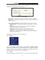
4.10.1 Dyndns.org DDNS
If your selected dynamic DNS Service Provider is www.dyndns.org The page shown in
Figure 4-44 will appear:
Figure 4-44
Dyndns.net DDNS Settings
To set up for DDNS, follow these instructions:
41
TL-R4000
1.
2.
3.
4.
Enterprise Broadband Router User Guide
Enter the User Name for your DDNS account.
Enter the Password for your DDNS account.
Enter the domain names your dynamic DNS service provider gave.
Click the Login button to login the DDNS service.
Connection Status - The status of the DDNS service connection is displayed here.
Click Logout to logout the DDNS service.
4.10.2 Oray.net DDNS
If your selected dynamic DNS Service Provider is www.oray.net. The page shown in
Figure 4-45 will appear:
Figure 4-45
Oray.net DDNS Settings
To set up for DDNS, follow these instructions:
1.
2.
3.
Enter the User Name for your DDNS account.
Enter the Password for your DDNS account.
Enter the Login button to login the DDNS service.
¾
Connection Status - the status of the DDNS service connection is displayed here.
¾
Domain Name - the domain names are displayed here.
Click Logout to logout the DDNS service.
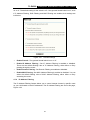
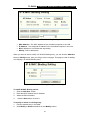
4.10.3 Comexe.cn DDNS
If your selected dynamic DNS Service Provider is www.comexe.cn. The page will
appear that shown in Figure 4-46:
42
TL-R4000
Figure 4-46
Enterprise Broadband Router User Guide
Comexe.cn DDNS Settings
To set up for DDNS, follow these instructions:
1. Enter the Domain names your dynamic DNS service provider gave.
2. Enter the User Name for your DDNS account.
3. Enter the Password for your DDNS account.
4. Click the Login button to login to the DDNS service.
Connection Status: The status of the DDNS service connection is displayed here.
Click Logout to logout of the DDNS service.
43
TL-R4000
Enterprise Broadband Router User Guide
4.11 System Tools
Figure 4-47
the System Tools menu
There are eight submenus under the System Tools menu: Time, Firmware, Factory
Defaults, Backup & Restore, Reboot, Password, Log and Statistics. Click any of
them, and you will be able to configure the corresponding function. The detailed
explanations for each submenu are provided below.
4.11.1 Time
You can set the time manually or get GMT from the Internet for the router on this page :
Figure 4-48
¾
¾
¾
Time settings
Time Zone - Select your local time zone from this pull down list.
Date - Enter your local date in MM/DD/YY into the right blanks.
Time - Enter your local time in HH/MM/SS into the right blanks.
Time setting follows these steps below:
1. Select your local time zone.
2. Enter date and time in the right blanks
3.
Click Save.
Click the Get GMT button to get GMT time from Internet if you have connected to the
Internet.
) Note:
1. This setting will be used for some time-based functions such as firewall. You
must specify your time zone once you login to the router successfully, if not the
time limited on these functions will not take effect.
44
TL-R4000
Enterprise Broadband Router User Guide
2. The time will be lost if the router is turned off.
3. The router will obtain GMT automatically from Internet if it has already connected
to Internet.
4.11.2 Firmware
The page shown in Figure 4-49 allows you to upgrade to the latest version of firmware
for the router.
Figure 4-49
Firmware Upgrade
You can find the latest version firmware at the TP-LINK website (www.tp-link.com) and it
can be downloaded free. It is not necessary to download a more recent version firmware,
unless that version has a new feature that you want to use.
To upgrade the router's firmware, follow these instructions:
1. Download a more recent firmware upgrade file from the TP-LINK website
(www.tp-link.com).
2.
Click the Browser button, find the update file. Then the textbox will display the exact
path of the file.
3.
Click the Upgrade button.
Firmware Version - displays the current firmware version.
Hardware Version - displays the current hardware version. The hardware version
of the upgrade file must accord with the current hardware version.
¾
¾
) Note:
1. The upgrade firmware should correspond to the hardware. Upgrade process
lasts for 20 seconds and the router will restart automatically then. Keep the
router is on power during the process, in case of any damage.
4.11.3 Factory Defaults
This page shown in Figure 4-50 allows you to restore the factory default settings for the
router.
45
TL-R4000
Enterprise Broadband Router User Guide
Figure 4-50
Restore Factory Default
Click the Restore button to reset all configuration settings to their default values.
• The default User Name: admin
• The default Password: admin
• The default IP Address: 192.168.1.1
• The default Subnet Mask: 255.255.255.0
) Note:
Any settings you have saved will be lost when the default settings are restored.
4.11.4 Backup & Restore Configuration
This page shown in Figure 4-51 allows you to save and restore all configuration settings
in the router.
Figure 4-51
Backup & Restore Configuration
Click the Backup button to save all configuration settings to your local computer as a file.
To restore the router's configuration, follow these instructions:
• Click the Browse button to find the configuration file which you want to restore.
• Click the Restore button.
) Note:
The current configuration will be covered with the uploading configuration file. Wrong
process will lead the device unmanaged. The restoring process lasts for 20 seconds and
restart automatically then. Keep the router is on power during restoring process, in case
of any damage.
4.11.5 Reboot
This page shown in Figure 4-52 allows you to reboot the router.
46
TL-R4000
Enterprise Broadband Router User Guide
Figure 4-52
Reboot the router
Click the Reboot button to reboot the router.
Some settings of the router will take effect only after rebooting, which include:
•
Change LAN IP Address. (System will reboot automatically)
•
MAC Clone (system will reboot automatically)
•
DHCP service function.
•
Static address assignment of DHCP server.
•
Web Service Port of the router.
•
Upgrade the firmware of the router (system will reboot automatically).
•
Restore the router's settings to factory default (system will reboot
automatically).
4.11.6 Password
This page shown in Figure 4-53 allows you to change the factory default user name and
password of the router.
Figure 4-53
Password
It is strongly recommended that you change the factory default user name and password
of the router. All users who try to access the router's web-based utility will be prompted
for the router's user name and password.
) Note:
The new user name and password must not exceed 14 characters in length and must not
include any spaces. Enter the new Password twice to confirm it.
Click the Save button when finished.
Click the Clear All button to clear all.
47
TL-R4000
Enterprise Broadband Router User Guide
4.11.7 Log
This page shown in Figure 4-54 allows you to query the Logs of the router.
Figure 4-54
System Log
The router can keep logs of all traffic. You can query the logs to find what happened to
the router.
Click the Refresh button to refresh the logs.
Click the Clear Log button to clear all the logs.
4.11.8 Statistics
The Statistics page shown in Figure 4-55 displays the network traffic of each PC on LAN,
including total traffic and traffic of the last Packets Statistic interval seconds.
Figure 4-55
Statistics
¾
Current Statistics Status - Enabled or Disabled. The default value is disabled. To
enable, click the Enable button. If disabled, the function of DoS protection in
Security settings will be ineffective.
¾
Packets Statistics Interval - The default value is 10. Select a value between 5 and
60 seconds in the pull-down list. The Packets Statistic interval value indicates the
time section of the packets statistic.
48
TL-R4000
¾
Enterprise Broadband Router User Guide
Sorted Rules - Here displays sort as desired.
Statistics Table:
IP Address
Total
Packets
The total amount of packets received and transmitted by the router.
Bytes
The total amount of bytes received and transmitted by the router.
Packets
Bytes
Current
The IP address displayed with statistics
ICMP Tx
UDP Tx
The total amount of packets received and transmitted in the last Packets
Statistic interval seconds.
The total amount of bytes received and transmitted in the last Packets
Statistic interval seconds.
The total amount of the ICMP packets transmitted to WAN in the last
Packets Statistic interval seconds.
The total amount of the UDP packets transmitted to WAN in the last
Packets Statistic interval seconds.
TCP
The total amount of the TCP SYN packets transmitted to WAN in the last
SYN Tx
Packets Statistic interval seconds.
Click the Auto-refresh checkbox to refresh automatically.
Click the Refresh button to refresh immediately.
Click the Reset All button to reset the statistics.
Click the Delete All button to delete all the entries in the statistics table.
49
TL-R4000
Enterprise Broadband Router User Guide
Appendix A: FAQ
1.
How do I configure the router to access Internet by ADSL users?
1)
2)
First, configure the ADSL modem configured in RFC1483 bridge model.
Connect the Ethernet cable from your ADSL modem to the WAN port on the
router. The telephone cord plugs into the Line port of the ADSL modem.
Login to the router, click the “Network” menu on the left of your browser, and
click "WAN" submenu. On the WAN page, select “PPPoE” for WAN Connection
Type. Type user name in the “User Name” field and password in the “Password”
field, finish by clicking “Connect”.
3)
Figure A-1
4)
PPPoE Connection Type
If your ADSL lease is in “pay-according-time” mode, select “Connect on
Demand” or “connect Manually” for Internet connection mode. Type an
appropriate number for “Max Idle Time” to avoid wasting paid time. Otherwise,
you can select “Auto-connecting” for Internet connection mode.
Figure A-2
PPPoE Connection Mode
) Note:
i.
ii.
2.
Sometimes the connection cannot be disconnected although you specify a
time to Max Idle Time, since some applications visit the Internet continually
in the background.
If you are a Cable user, please configure the router following the above
steps.
How do I configure the router to access Internet by Ethernet users?
1)
Login to the router, click the “Network” menu on the left of your browser, and
click "WAN" submenu. On the WAN page, select “Dynamic IP” for "WAN
Connection Type", finish by clicking “Save”.
50
TL-R4000
2)
Enterprise Broadband Router User Guide
Some ISPs require that you register the MAC address of your adapter, which is
connected to your cable or DSL modem during installation. If your ISP requires
MAC register, login to the router and click the "Network" menu link on the left of
your browser, and then click "MAC Clone" submenu link. On the "MAC Clone"
page, if your PC’s MAC address is a proper MAC address, click the "Clone
MAC Address" button and your PC’s MAC address will fill in the "WAN MAC
Address" field. Or else, type the MAC address into the " WAN MAC Address"
field. The format for the MAC address is XX-XX-XX-XX-XX-XX. Then click the
"Save" button. It will take effect after rebooting.
Figure A-3
3.
MAC Clone
I want to use Netmeeting, what do I need to do?
1)
2)
3)
If you start Netmeeting as a sponsor, you don’t need to do anything with the
router.
If you start as a responsor, you need configure Virtual Server or DMZ Host.
How to configure Virtual Server: Login to the router, click the “Forwarding” menu
on the left of your browser, and click " Virtual Servers" submenu. On the "Add or
Modify a Virtual Server Entry" page, enter “1720” into the blank below the
“Service Port”, and your IP address below the IP Address, assuming
192.168.1.169 for an example, remember to “Enable” and “Save”.
Figure A-4
Virtual Server
) Note:
Your opposite side should call your WAN IP, which is displayed on the “Status”
page.
51
TL-R4000
4)
Enterprise Broadband Router User Guide
How to enable DMZ Host: Login to the router, click the “Forwarding” menu on
the left of your browser, and click " DMZ" submenu. On the "DMZ" page, click
“Enable” radio and type your IP address into the “DMZ Host IP Address” field,
using 192.168.1.169 as an example, remember to click the "Save” button.
Figure A-5
4.
DMZ
I want to build a WEB Server on the LAN, what should I do?
1)
2)
Because the WEB Server port 80 will interfere with the WEB management port
80 on the router, you must change the WEB management port number to avoid
interference.
To change the WEB management port number: Login to the router, click the
“Security” menu on the left of your browser, and click "Remote Management"
submenu. On the "Remote Management" page, type a port number except 80,
such as 88, into the "Web Management Port" field. Click “Save” and reboot the
router.
Figure A-6
Remote Management
) Note:
If the above configuration takes effect, to configure to the router by typing
http://192.168.1.1:88 (the router’s LAN IP address: Web Management Port) in
the address field of the web browser.
3) Login to the router, click the “Forwarding” menu on the left of your browser, and
click the "Virtual Servers" submenu. On the "Add or Modify a Virtual Server
Entry" page, enter “80” into the blank below the “Service Port”, and your IP
address below the IP Address, assuming 192.168.1.188 for an example,
remember to “Enable” and “Save”.
52
TL-R4000
Enterprise Broadband Router User Guide
Figure A-7
Virtual Server
53
TL-R4000
Enterprise Broadband Router User Guide
Appendix B: Configuring the PCs
In this section, we’ll introduce how to install and configure the TCP/IP correctly in
Windows XP. First make sure your Ethernet Adapter is working, refer to the adapter’s
manual if needed.
1.
Install TCP/IP component
1)
On the Windows taskbar, click the Start button, point to Settings, and then click
Control Panel.
2)
Click the Network and Internet Connections icon, and then click on the
Network Connections tab in the appearing window.
3)
Right click the icon that showed below, select Properties on the prompt page.
Figure 1
4)
In the prompt page that showed below, double click on the Internet Protocol
(TCP/IP).
54
TL-R4000
Enterprise Broadband Router User Guide
Figure 2
5)
The following TCP/IP Properties window will display and the IP Address tab is
open on this window by default.
Now you have two ways to configure the TCP/IP protocol below:
¾ Setting IP address automatically
Select Obtain an IP address automatically, Choose Obtain DNS server
automatically, as shown in the Figure below:
55
TL-R4000
Enterprise Broadband Router User Guide
Figure 3
¾ Setting IP address manually
1
Select Use the following IP address radio button. And the following items available
2
If the router's LAN IP address is 192.168.1.1, type IP address is 192.168.1.x (x is
from 2 to 254), and Subnet mask is 255.255.255.0.
3
Type the router’s LAN IP address (the default IP is 192.168.1.1) into the Default
gateway field.
4
Select Use the following DNS server addresses radio button. In the Preferred
DNS Server field you can type the DNS server IP address, which has been provided
by your ISP
56
TL-R4000
Enterprise Broadband Router User Guide
Figure 4
57
TL-R4000
Enterprise Broadband Router User Guide
Appendix C: Specifications
General
Standards
IEEE 802.3, 802.3u
Protocols
TCP/IP, PPPoE, DHCP, ICMP, NAT, SNTP
Ports
Four 10/100M Auto-Negotiation LAN RJ45 ports supporting Auto
MDI/MDIX
One 10/100M Auto-Negotiation WAN RJ45 port.
One 100M Fiber Module Expansion Slot
(Shared with WAN RJ45 port)
One Console (RS232 DB9 Male)
Cabling Type
10BASE-T: UTP category 3, 4, 5 cable (maximum 100m)
EIA/TIA-568 100Ω STP (maximum 100m)
100BASE-TX: UTP category 5, 5e cable (maximum 100m)
EIA/TIA-568 100Ω STP (maximum 100m)
LEDs
Power, M1, M2, Link/Act, Speed
Environmental and Physical
Operating Temp.
0℃~40℃ (32℉~104℉)
Operating Humidity
10% - 90% RH, Non-condensing
Optional Module
TL-SM21CM
100Base-FX Multi-Mode Fiber Module
(SC connector, up to 2km)
TL-SM21CS-20/40/60
100Base-FX Single-Mode Fiber Module
(SC connector, up to 20/40/60km)
58
TL-R4000
Enterprise Broadband Router User Guide
Appendix D: Glossary
¾
DDNS (Dynamic Domain Name System) - The capability of assigning a fixed host
and domain name to a dynamic Internet IP address.
¾
DHCP (Dynamic Host Configuration Protocol) - A protocol that automatically
configure the TCP/IP parameters for the all the PCs that are connected to a DHCP
server.
¾
DMZ (Demilitarized Zone) - A Demilitarized Zone allows one local host to be exposed
to the Internet for a special-purpose service such as Internet gaming or
videoconferencing.
¾
DNS (Domain Name Server) - An Internet Server that translates the names of
websites into IP addresses.
¾
Domain Name - A descriptive name for an address or group of addresses on the
Internet.
¾
DoS (Denial of Service) - A hacker attack designed to prevent your computer or
network from operating or communicating.
¾
DSL (Digital Subscriber Line) - A technology that allows data to be sent or received
over existing traditional phone lines.
¾
ISP (Internet Service Provider) - A company that provides access to the Internet
¾
MTU (Maximum Transmission Unit) - The size in bytes of the largest packet that
can be transmitted.
¾
NAT (Network Address Translation) - NAT technology translates IP addresses of a
local area network to a different IP address for the Internet.
¾
PPPoE (Point to Point Protocol over Ethernet) - PPPoE is a protocol for connecting
remote hosts to the Internet over an always-on connection by simulating a dial-up
connection.
59