1
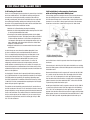
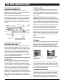
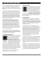
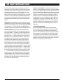
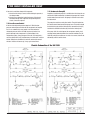
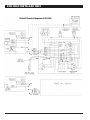
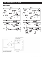
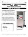
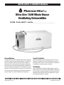
INSTALLER’S & OWNER’S MANUAL
Ultra-Aire 150H Whole House
Ventilating Dehumidifier
UA-150H • Part No. 4024371 • Serial No.________________________________
Dehumidification
Fresh Air Ventilation
The highly efficient Ultra-Aire 150H dehumidifier utilizes refrigeration
to cool the incoming air stream below its dew point. This cooled and
drier air is used to pre-cool the incoming air stream resulting in a
significant increase in overall efficiency. After the pre-cooling stage,
the processed air is reheated by passing through the condenser coil.
The heat removed by the evaporator coil is returned to the air stream,
resulting in an overall temperature increase of the air leaving the unit.
Optional fresh outdoor air may be ducted to the unit via a six inch
round duct. This provides fresh air to dilute pollutants and maintain
high oxygen content in the air. The amount of fresh air ventilation can
be regulated by a variety of dampers and controls.
The Ultra-Aire 150H is controlled by 24 volt remote wired controls. A
variety of controls are available suitable to various applications.
Air Filtration
The UA-150H includes air filtration to improve indoor air quality. A
MERV-11 media filter is standard. An optional MERV-14 deep pleated
95% media filter is available for optimum air filtration and to reduce
potentially harmful airborne particles. If the optional filter is chosen,
the standard filter operates as a prefilter.
HVAC INSTALLER: PLEASE LEAVE MANUAL FOR HOMEOWNER
© 2006 Therma-Stor LLC
Manual P/N TS-245h 6/07
TABLE OF CONTENTS
Table of Contents
Safety Precautions........................................................................ 3
5.3H Damper Operation and Setting ................................ 13
1. Intended Application................................................................. 4
5.3I Intermittent/Programmed Ventilation ........................ 14
2. Specifications .......................................................................... 4
5.3J Programming Notes . ............................................... 14
3. Installation . ............................................................................. 4
5.3K Ventilating or Dehumidifying to Control
3.1 Location............................................................................ 4
Indoor Relative Humidity Levels ....................................... 14
3.2 Electrical Requirements..................................................... 4
5.3L Stop Start ................................................................ 14
3.3 Condensate Removal......................................................... 5
5.3M Low Pressure Control ............................................. 14
3.4 Ducting.............................................................................. 5
6. Maintenance.......................................................................... 15
3.4A Installing Duct Collars . .............................................. 5
6.1 Standard Air Filter............................................................ 15
3.4B Ducting for Dehumidification...................................... 5
6.2 High Efficiency Air Filter................................................... 15
3.4C Ducting for Fresh Air................................................... 6
6.3 Impeller Fan Oiling........................................................... 15
3.4D Installation in a Basement ......................................... 6
6.4 Fresh Air Return ............................................................. 15
3.4E Installation in a attic................................................... 7
7. Service................................................................................... 15
3.4F Installation with (2) HVAC systems.............................. 7
7.1 Warranty . ....................................................................... 15
3.4G Installation without an HVAC system........................... 7
7.2 Technical description....................................................... 15
3.5 Quiet Installation................................................................ 7
7.3 Troubleshooting............................................................... 16
4. Controls ................................................................................... 7
7.4 Refrigerant Charging ...................................................... 17
4.1 Humidity/Fan Control Panel................................................ 7
7.5 Impeller Fan Replacement .............................................. 17
4.2 Ventilation Timer & Humidity Control Panel........................ 8
7.6 Compressor/Capacitor Replacement................................ 17
4.3 Humidity Control Adjustment............................................. 8
7.6A Checking Compressor Motor Circuits . ..................... 17
4.4 Fan/Filter Switch................................................................ 8
7.6B Replacing Burned Out Compressor . ........................ 17
4.5 Ventilation Timer................................................................ 8
7.6C Replacing Compressor-Nonburn Out....................... 18
4.6 Low Pressure Control........................................................ 9
7.7 Remote Controls.............................................................. 18
DEH Wiring Diagram.............................................................. 10
7.7A Humidity Control....................................................... 18
5. DEH 2000 Digital Control ....................................................... 11
7.7B Ventilation Timer....................................................... 18
5.1 Specifications . ............................................................... 11
7.8 Defrost Thermostat.......................................................... 18
5.2 Installation . .................................................................... 11
7.9 Electric Ventilation Damper.............................................. 18
5.2A Install Instructions ................................................... 11
7.10 Low Pressure Control.................................................... 19
5.2B Wiring ..................................................................... 11
7.11 Condensate Pump Kit.................................................... 19
5.2C Location .................................................................. 12
Electrical Schematic .................................................................. 19
5.3 Operation ....................................................................... 12
Pictorial Electrical Diagram......................................................... 20
5.3A Display .................................................................... 12
Wiring Diagrams......................................................................... 21
5.3B Setting .................................................................... 12
Service Parts List . ..................................................................... 22
5.3C On/Off Setting ......................................................... 12
Optional Parts List ..................................................................... 23
5.3D Setting Clock Time .................................................. 12
Vibration Isolation Kit:................................................................. 24
5.3E Setting Relative Humidity Set point .......................... 13
External Insulation Kit........................................................... 25, 26
5.3F Fan Setting and Operation ....................................... 13
Warranty..................................................................................... 27
5.3G Fan On Fan Off Fan Program ................................... 13
2
Ultra-Aire 150H Installer’s & Owner’s Manual
SAFETY PRECAUTIONS
1. Safety Precautions
Read the installation, operation and maintenance instructions
carefully before installing and operating this device. Proper
adherence to these instructions is essential to obtain maximum
benefit from your UA-150H indoor air quality system.
READ AND SAVE THESE INSTRUCTIONS
• The device is designed to be installed INDOORS IN A SPACE THAT
IS PROTECTED FROM RAIN AND FLOODING.
• Install the unit with space to access the front panel for
maintenance and service. DO NOT INSTALL UNIT WITH THE
FRONT PANEL INACCESSIBLE.
• Avoid directing the discharge air at people, or over the water in
pool areas.
• If used near a pool or spa; be certain there is NO chance the unit
could fall into the water, splashed and that it is plugged into a GFI
GROUND FAULT INTERRUPT OUTLET.
• DO NOT use the device as a bench or table.
• DO NOT place the device directly on structura lmembers.
• A drain pan MUST be placed under the unit ifinstalled above a
living area or above an areawhere water leakage could cause
damage
3
Ultra-Aire 150H Installer’s & Owner’s Manual
FOR HVAC INSTALLER ONLY
1. Intended Application for Ultra-Aire 150H
Place the UA-150H on supports that raise the base of the unit
above the top of the flanges on the drain pan beneath it. Raising the
UA-150H will help the unit drain with gravity flow. Do not place the
UA-150H directly on structural building members without vibration
absorbers or unwanted noise may result.
For the ideal installation, draw air from the central part of the home
and return it to isolated areas of the home like the bedrooms, den,
utility room, or family room. The ductwork of the existing heating
system can be used to supply air to the home.
The UA-150H may be suspended with steel hanger straps (plumbers
tape) or a suitable alternative from structural members. Remember
to place a drain pan under the unit if it is suspended above a finished
area or above an area where water leakage could cause damage.
2. Specifications
Model: UA-150H Indoor Air Quality System
Electrical: 110-120 VAC, 12 Amps, 60 Hz,
grounded
Capacity: 145 pints/day @ 80°F, 60% RH
Operating Temp. Range: 56°F min., 100°F max.
Air Flow: 400 CFM without external ducting
355 CFM @ .20 IWG external static
290 CFM @ .40 IWG external static
Refrigerant Charge: 2 lb., 2 oz. R-22
Duct connections: Round 10" & 6" inlets, 10" outlet
The UA-150H should be located near the existing air handling
system to minimize the required ductwork for connecting the
UA-150H to the existing air handling system. The controls for the
UA-150H are remote from the unit and must be located in the space
that is to be conditioned. The controls are low voltage (24 volt) and
should be connected to the UA-150H with low voltage thermostat
cable.
An external insulation kit is available for the UA-150H. This will
prevent the cabinet from sweating if the unit is installed in an
unconditioned space. This kit will also increase the efficiency of the
unit by eliminating unwanted heat transfer between the unit and the
unconditioned space. See the optional parts list for information on
the kit.
Filter Size: Pleated cloth: 2" X 20" X 24" High Efficiency: 4" X 20"
X 24"
Size (w/o duct collars): 453/4" long x 24 3/4" wide x 20 1/2" high
Unit Weight: 145 lb., Shipping Weight 229 lb.
If fresh air ventilation is desired, thought should be given to the
location for the fresh air ducting. A 6” round insulated duct will
have to be installed on the UA-150H and run to the outside of the
structure to bring in fresh air. Use an 8” insulated round duct for
lengths of more than 50 feet or if more than 100 CFM is needed.
Consult local codes for necessary distances from exhaust ports
when installing fresh air return.
3. Installation
3.1 Location
The UA-150H can be installed in a variety of locations to meet
the owner's needs as listed below. In all cases keep the following
cautions in mind:
• It is designed to be installed INDOORS IN A SPACE THAT IS
PROTECTED FROM RAIN AND FLOODING.
3.2 Electrical Requirements
WARNING: DO NOT ALLOW THE YELLOW LEAD FROM THE
• Install the unit with space to access the front panel for
maintenance and service. Also allow easy access to the filter cover
panel. DO NOT INSTALL UNIT WITH THE FRONT PANEL OR FILTER
COVER PANEL INACCESSIBLE.
ULTRA-AIRE TO CONTACT THE RED LEAD OR ORANGE LEAD
FROM THE ULTRA-AIRE OR DAMAGE TO THE TRANSFORMER
WILL RESULT.
• Avoid discharging the air directly at people, or over the water in
pool areas.
The UA-150H plugs into a common grounded outlet on a 15 or
20 Amp circuit. It draws around 12 Amps under normal operating
conditions. If used in a wet area (pool, spa room, or basement prone
to flooding), a ground fault interrupter protected circuit is required.
• If used near a pool or spa, be certain there is NO chance the unit
could fall into the water or be splashed and that it is plugged into a
GROUND FAULT INTERRUPTER.
Install the remote control panel in a central area of the structure
where it will sense the relative humidity of the structure accurately.
Do not install the control panel where it may not accurately sense
the relative humidity such as near HVAC supply registers, near
exterior doors, or near a pool or spa. The installer must supply the
wiring between the UA-150H and the control panel. Be sure to safely
route the control wiring to prevent damage during installation. Be
• DO NOT use the UA-150H as a bench or table.
• DO NOT place the UA-150H directly on structural members.
• A drain pan MUST be placed under the unit if installed above a
living area or above an area where water leakage could cause
damage.
4
Ultra-Aire 150H Installer’s & Owner’s Manual
FOR HVAC INSTALLER ONLY
3.4B Ducting for Dehumidification
careful not to cross the wires when connecting the UA-150H and the
remote control panel or damage to the transformer may result.
For the ideal installation, draw air from the central part of the home
and return it to the isolated areas of the home like the bedrooms,
den, utility room, or family room. The ductwork of the existing
heating system can be used to supply air to the home. If the existing
supply goes to isolated areas of the home, discharge the supply of
the UA-150H into the supply of the existing heating system. If the
existing heating system incorporates a central supply, installation of
a separate supply duct from the UA-150H to each isolated area is
recommended. DO NOT draw air directly from the kitchen, laundry,
or isolated basement. You may draw air from a basement that is
open to the home. All flexible ducting connected to the UA-150H
should be UL listed.
The remote controls of the UA-150H are powered by a low voltage
circuit (24 Vac) and must NEVER contact or be connected to a high
voltage circuit. The control wires leaving the UA-150H and the
remote control panels are numbered and color-coded to prevent
confusion. Some of the control wires leaving the UA-150H may
not be used with certain control panels and should be left safely
disconnected with wire nuts taped onto the stripped ends. Be sure to
consult the electrical schematic in this manual or inside the access
panel of the UA-150H before making the control connections.
NOTE: RESET THE VENTILATION TIMER BEFORE ATTEMPTING
TO PROGRAM AFTER INITIAL INSTALLATION. THE TIMER MAY
NOT OPERATE CORRECTLY UNTIL IT IS RESET.
The inlet of the UA-150H is the 10” diameter hole in the filter
enclosure of the unit. A 10” round collar is supplied with the unit
to attach to round duct. The duct may be permanently attached to
the collar. A 6” round collar is provided with the unit to attach to
the 6” hole in the filter enclosure. The 6” collar should be capped if
fresh make-up air is not desired. If fresh make-up air is desired see
section 3.4C.
A decorative picture frame is provided to cover the control panel. The
home owner may use their choice of picture frames.
If an extension cord is required, it must have a minimum of 12 gauge
conductors if 25 feet long or less and 10 gauge conductors if greater
than 25 feet long.
The outlet of the UA-150H is located on the end of the unit. A second
10” round collar is supplied with the unit. Cut and remove the safety
grid, then bend the tabs on the collar inside the hole in the cabinet
end.
3.3 Condensate Removal
Condensate drains by gravity via the clear hose extending from the
unit. Route the hose to a suitable drain. Use care to keep the hose
as flat to the floor as possible, excessive humps will prevent proper
drainage. We do not call for a trap since there is an internal trap with
this unit.
A length of 6 feet or more of acoustical flex ducting on the outlet of
the UA-150H will reduce air noise from the impeller fan. A length of
flexible ducting on all UA-150H duct connections is recommended
to reduce noise and vibration transmitted to rigid ductwork in the
structure.
If the UA-150H is located too far from a floor drain for the attached
hose to reach, inexpensive 1/2" PVC pipe can be used to extend it. It
is commonly available in 10' lengths from building supply, plumbing
or hardware stores. It will slide tightly inside the end of the drain
hose. If more than one length of pipe is required, they can be joined
with a short piece cut from the end of the drain hose.
Ducting the UA-150H as mentioned in sections 3.4A-3.4G requires
consideration of the following points:
Duct Sizing: For total duct lengths up to 25', use a minimum 10"
diameter round or equivalent rectangular. For longer lengths, use a
minimum 12" diameter or equivalent. Grills or diffusers on the duct
ends must not excessively restrict airflow.
An optional condensate pump kit may be installed if a lift is required
to dispose of the condensate. The condensate pump kit can be
ordered direct from the factory. See the optional parts list for
information on the kit.
Isolated Areas: Effective dehumidification may require that ducting
be branched to isolated, stagnant areas. Use 8" or larger diameter
branch ducting to each of two or three areas, use 6" or larger to
each of four or more areas.
3.4 Ducting
3.4A Installing Duct Collars
The UA-150H is equipped with 10” and 6” round inlet collars and
a 10” round exhaust collar. The 10” and 6” round inlet collars are
designed with tabs that fold inside the filter enclosure of the UA150H. The 10” round exhaust collar is attached to the UA-150H by
folding the tabs inside the end panel of the UA-150H.
Connecting to existing HVAC systems: An optional 10" check damper
is available from the factory to prevent reverse flow through the
UA-150H. If the UA-150H is ducted to the supply of a high static air
handler the check damper may be placed in the UA-150H supply
duct. Contact the factory when connecting to a static pressure of
greater than or equal to +.5” WG.
To install the collars; Insert the tabs of the collar into the hole in the
filter enclosure and/or end panel of the UA-150H and fold the tabs
up to attach to UA-150H.
5
Ultra-Aire 150H Installer’s & Owner’s Manual
FOR HVAC INSTALLER ONLY
3.4C Ducting for Fresh Air
3.4D Installation in a Basement or Crawlspace
with an Existing Forced Air HVAC System
Fresh air can be brought into the structure by connecting a insulated
duct from outside to the 6” UA-150H inlet and by turning on the
fan switch or activating the humidity control (on units with the
humidity control panel). Activate the ventilation timer on units with
the ventilating & humidity control panel to bring in fresh air. Refer
to section 4.5 for programming instructions for the ventilation timer.
Advantages of this form of ventilation include:
If the existing system has multiple returns, select one to disconnect
from the existing forced air system and use it for the dedicated
UA-150 return. Always select a return from a central location in the
structure in an area that is always open to the rest of the structure.
Do not use a return from a room that may have its’ door closed
1. Outside air is filtered before entering the building.
2. Outside air will be dehumidified before entering if the UA-150H
is running in dehumidification mode.
3. Drawing air from outside and blowing inside aids in slightly
pressurizing the structure. This helps prevent dirty and humid
air from entering elsewhere. It also reduces the potential for
carcinogenic radon gas to enter and provides make-up air for
open combustion and exhaust devices like the clothes drier,
fireplace, and water heater.
4. Adequate exhaust fans are recommended in the bath rooms
and kitchen.
In cold climates or areas where the outdoor dew point is low
at times, ventilation can be used to dehumidify the structure.
This is accomplished by bringing the dry, low dew point air into
the structure during these times. This approach is often more
economical than running the dehumidifier to remove excess
moisture from the structure. In cold climates, it is critical to
adequately ventilate to reduce the inside moisture content to
avoid moisture accumulating in the wall cavities. For example; in a
house that experiences condensation on the interior surface of the
windows during the winter, increasing the amount of ventilation will
often cure the problem.
much of the time or install a separate return from the open part of
the house.
If the structure in which the UA-150 is to be installed has an existing
forced air HVAC system, utilize the HVAC system to make the UA-150
installation easier.
Basement Installation: Install a separate 10” return for the UA-150H
in a central area of the structure. Duct the supply of the UA-150 to
a 10” x 10” x 10” tee/damper that is 20% open to the basement.
Duct the other side of the tee to the air supply of the existing HVAC
system. Connect a duct from outside to the 6” collar of the UA-150
if you wish to provide fresh make-up air.
An insulated 6" diameter duct is generally sufficient to provide up
to 125 CFM of outside air. Large quantities of outside air will impact
UA-150H performance positively or negatively, depending upon
the inside and outside air conditions. Consult the factory by calling
1-800-533-7533 for recommendations regarding the use of higher
flows with your specific application.
Crawl Space Installation: Install a separate return for the UA-150H in
a central area of the structure. Duct the supply of the UA-150H to a
10” x 10” x 10” tee/damper that is 20% open to the crawl space if
desired. Duct the other side of the tee to the air supply of the existing
HVAC system. Connect an insulated duct from outside to the 6” collar
of the UA-150H if you wish to provide optional fresh make-up air.
The outside air duct should be connected to the 6” round collar on
the filter enclosure of the unit. The 6” round collar includes a manual
damper. Adjust the manual damper to provide the desired amount of
fresh air for ventilation. The amount of fresh air should be based on
the size and occupancy of the residence. If you are unsure of your
ventilation air requirements, consult the factory by calling 1-800533-7533 for assistance.
6
Ultra-Aire 150H Installer’s & Owner’s Manual
FOR HVAC INSTALLER ONLY
3.4E Installation in an Attic with an
Existing Forced Air HVAC System
3.5 Quiet Installation
The compressor is attached to the cabinet with two cable ties to
secure it during shipment. This rigid attachment is not necessary
once the unit is installed and may cause noise from compressor
vibration. After installation, cut the cable ties to free the compressor
from the cabinet.
ALWAYS install a catch pan with a drain or float interrupt for
condensate under the UA-150H in an attic or condensate may drip
down on the ceiling of the living space below.
Locate a separate return for the UA-150H in a central area of the
structure. Duct the supply of the UA-150H to the air supply of the
existing HVAC system Connect an insulated duct from outside to
the 6” collar of the UA-150H if you wish to provide fresh make-up
air. Adjust a damper in the duct to provide the desired amount of
fresh air.
REMOVE THE HORIZONTAL CABINET SUPPORT TO WHICH THE
COMPRESSOR IS ATTACHED. The ends of the support are notched
so that the support can easily be removed. Cut the strips of metal on
each end and remove the support section from the cabinet. This will
prevent the compressor from transmitting vibration to the cabinet.
Make sure none of the compressor tubes are pressed against the
cabinet or access panel. Check that the compressor tubes are
centered in the holes where they pass through the drain pan.
A length of 10 feet or more of acoustical flex ducting on the outlet of
the UA-150H will reduce air noise from the impeller fan. A length of
flexible ducting on all UA-150H duct connections is recommended
to reduce noise and vibration transmitted to rigid ductwork in the
structure.
Install an external insulation kit.
4. Controls
The UA-150H can be equipped with various accessories to enhance
its operation. A remote control panel must be used with the UA150H. There are three remote control from which to choose. The
humidity/fan control panel is used to control humidity and the
impeller fan. Fresh air is introduced when the impeller fan operates.
3.4F Installation in a Structure with
Two Forced Air HVAC Systems
Attach the UA-150H return to an independent return from the upper
level. Attach the UA-150H supply to the supply of the basement
HVAC system. This will promote circulation of air through the whole
structure from the upper level to the lower level through the UA150H. If the UA-150H is not connected to both HVAC systems, it
will not control the humidity and ventilation of the entire structure.
Connect an insulated duct from outside to the 6” collar of the UA150H if you wish to provide fresh make-up air.
Figure 1:
Humidity/Fan Control Panel
Part No. 4024155
3.4G Installation in a Structure with No Existing Forced
Air HVAC System
When installing the UA-150H in a structure that does not have a
forced air HVAC system, a single return for the UA-150H should be
installed in central open area of the structure. DO NOT locate the
return in a bathroom or a kitchen. The supply of the UA-150H should
be located in the remote areas of the structure (such as bedrooms,
den, etc..). By ducting this way, the air inside the structure will
circulate through the UA-150H to be filtered and dehumidified. 4"
diameter duct is recommended for branches to the bedrooms, 6"
diameter duct is recommended for branches to larger areas. Refer to
section 3.4B for branch duct sizing. Connect an insulated duct from
outside to the 6” collar of the UA-150H if you wish to provide fresh
make-up air.
Figure 2: Ventilation Timer
and Humidity Control Panel
Part No. 4024125
The impeller fan operates when dehumidifying or the fan switch
is on. The ventilation timer and humidity control panel are used to
control humidity, the impeller fan, and preset ventilation schedules.
The quantity of fresh air should be 10 ft3/min of fresh air per person
plus 1 ft3/min per 100 ft2 of floor space.
4.1 Humidity/Fan Control Panel
See Figure 1: The humidity/fan control panel automatically controls
the humidity of the living space. The humidity/fan control panel
contains an adjustable humidity control and a fan switch. This panel
should be mounted in a central area of the structure where it can
accurately sense the humidity of the air in the living space. The
7
Ultra-Aire 150H Installer’s & Owner’s Manual
FOR HVAC INSTALLER ONLY
4.4 Fan/Filter Switch
panel has a cover that must remain open to the air within the living
space for accurate humidity sensing. Position the fan switch on
when the home is occupied. The impeller fan blends fresh air with
the inside air. It also filters and circulates the blended air throughout
the home.
Turning ON the fan/filter switch will cause the
the UA-150H impeller fan to run continuously,
whether the UA-150H is dehumidifying or not.
This function is desirable if the unit is used
for air circulation and filtration to achieve
maximum indoor air quality. When the switch
Figure 4
Fan/Filter Switch
is ON; air will be constantly filtered through the
UA-150H and circulated throughout the house.
When the switch is OFF the impeller fan will operate only when the
humidity control calls for dehumidification or when the ventilation
timer calls for ventilation.
The humidity/fan control panel can be used in conjunction with the
optional fresh air damper. When used with the optional fresh air
damper, the fan/filter switch will act as a fresh air ventilation control.
When the switch is ON (in this configuration), the impeller fan will
run, the fresh air damper will open, and fresh air will be filtered
and brought into the structure. When the switch is OFF, the fresh air
damper will close and the impeller fan will operate only when the
humidity control calls for dehumidification. Contact the factory for
instructions on this type of installation.
4.5 Ventilation Timer
The ventilation timer controls the impeller fan and the motorized
fresh air damper. When the ventilation timer is activated, the UA150H will circulate the indoor air, and bring in fresh air from outside.
The ventilation timer should be set for the required ventilation of the
residence. The home should be ventilated with fresh air as suggested
by applicable codes and standards. Minimally, ventilate when
occupied by plus two people.
4.2 Ventilation Timer and Humidity Control Panel
See Figure 2: The ventilation timer and humidity control panel
automatically controls both the ventilation and the humidity of
the living space. The ventilation timer and humidity control panel
contains an adjustable humidity control, a fan switch, and a
ventilation timer. This panel will control the humidity and allow
programmed ventilation of the living space. This panel works in
conjunction with the optional fresh air damper to provide ventilation.
The minimum fresh air ventilation schedule recommended is “on”
when occupied two or more people.
In cold climates or areas where the outdoor dew point is low at
times, ventilation can be used to dehumidify the structure. This is
accomplished by bringing the dry, low dew point air into the structure
during these times. This approach is often more economical than
running the dehumidifier to remove excess moisture from the
structure. For example; in a house that experiences condensation
on the interior surface of the windows during the winter, increasing
the amount of ventilation will often cure the problem. To avoid
condensation on windows and in walls, increase the ventilation
rate and duration immediately. Call the factory for assistance if
condensation is not eliminated.
This panel should be mounted in a central area of the structure
where it can accurately sense the humidity of the air in the living
space. The panel has a cover that must remain open to the air within
the living space for accurate humidity sensing.
4.3 Humidity Control Adjustment
Set the humidity control to the desired humidity
level for the home. Turning the knob clockwise
results in a drier setting. See the back of
the control panel cover for set points. The
dehumidifier will run continuously until the
relative humidity (RH) is reduced to the humidity
Figure 3:
Humidity Control control dial setting. Setting the humidity control
Adjustment Knob to lower RH levels will NOT increase the unit's
dehumidification rate; the unit will simply run
longer to reduce the area's RH to the setting. The UA-150H unit
(and refrigerant-based dehumidifiers in general) will reduce a warm
space's RH to a lower level than that of a cool space. It is therefore
pointless to set the humidity control to excessively low levels in cool
rooms; doing so will result in long periods of ineffective dehumidifier
run time. Settings below 45% are not recommended.
The ventilation timer is an electronic timer that displays the current
time. This timer has a battery backup, so it will not require resetting
after a power outage. Following a prolonged power outage the
display of the timer will flash on and off indicating a power outage
has occurred. The one-minute time increments of the ventilation
timer allow you to program the ventilation of your home to fit your
schedule.
The ventilation timer has six programs with each program having
one “on” and one “off” event. A program allows the user to turn the
ventilation on at a certain day and time, then it allows them to turn
the ventilation off at a certain day and time. Each of these programs
can be repeated daily or weekly or during a specified block of days.
All six of the programs operate independently of each other.
Quality humidity meters are available from the factory and are
recommended to accurately monitor humidity levels.
8
Ultra-Aire 150H Installer’s & Owner’s Manual
FOR HVAC INSTALLER ONLY
Automatic or Manual Mode: The slide switch in the upper left of
the timer is used to choose between automatic and manual operation
of the timer relay. When the slide switch in the upper left of the timer
is set to AUTO mode, the UA-150H will ventilate when the scheduled
programs call for ventilation. When the slide switch in the upper left
of the timer is set to manual (set to hand symbol on the right), the
operation of the timer is controlled by the I/O button only. Pressing
the I/O button will switch the ventilation timer between ON (detent)
and OFF (detent). As you press the I/O button, “ON” or “OFF” will
be displayed to the right of the time. The “ON” or “OFF” to the right
of the time will indicate if the ventilation timer is on or off. The I/O
button will manually override scheduled programs if the timer is in
AUTO mode.
If the timer fails to operate or operates erratically, check that the
control panel receives 24Vac from the UA-150H. If 24Vac is present
at the control panel, reset the timer by pressing the reset button at
the bottom center of the timer face. The reset button is the small
recessed button with an R beneath it located below the 1…7 and h
buttons. Press the reset button in until the display clears. Release the
reset button. The display will reappear as 00:00. Resetting the timer
will clear the time and all program settings. After resetting the timer
follow the instructions below to set the correct time and ventilation
programs.
Setting The Time: The following instructions explain how to set the
ventilation timer. First, set the correct time on the timer by sliding the
switch in the upper right hand corner of the timer to the clock symbol
• and pressing the 1…7 (DAY), h (HOUR), and m (MINUTE) buttons.
Remember that this timer operates on a 24-hour (military time) clock.
4.6 Low Pressure Control
If the low side refrigerant pressure drops to 15 PSIG, the lowpressure control opens and shuts off the compressor and impeller
fan. It is an automatically reset control that will close when the
pressure rises to 35 PSIG. Its primary function is to prevent damage
to the compressor if a leak develops in the refrigeration system. It
may also open if the unit is A) installed in a cool area (below 50 F)
or B) installed where it is below 40 F and then started. Under these
conditions, the unit will restart within several minutes. Until the unit
warms up, it may repeat the cycle several times.
Ventilation Schedule: Slide the switch in the upper right hand
corner to the program symbol P. “ON” will appear to the right of the
time and the number “1” will appear in the lower right hand corner
of the display. The “1” and “ON” signify the turn on time for the first
program. Press the 1…7 button to choose the days of the week for
this program. You can choose Mon.-Sun, Mon.-Fri., Sat-Sun, or any
single day of the week. The days chosen are shown along the top
of the display on the ventilation timer. Next press the h button to
set the hour for the start of the ventilation period. Remember that
this timer operates on a 24-hour clock. Then press the m button to
set the minutes past the hour to start the ventilation. Now, with the
ventilation start time set; press the I/O button. The word “OFF” should
appear to the right of the time and the number “1” should remain in
the lower right hand corner of the display. The “1” and “OFF” signify
the turn off time for the first program. Set the turn off time using the
1…7, h, and m buttons in the same way as described above and
continue on to the second through sixth programs. When setting the
ventilation programs, you can return to the current time display by
sliding the switch in the upper right corner of the timer to RUN. The
slide switch in the upper right must be set to RUN for the timer to
operate with the scheduled programs.
9
Ultra-Aire 150H Installer’s & Owner’s Manual
ATTENTION INSTALLER
WIRE THE UNIT AND CONTROL PACKAGE AS SHOWN IN THE DIAGRAM BELOW
WARNING: DO NOT allow the yellow lead from the unit to contact the red lead or the white
lead from the unit or damage to the transformers will result. Do not direct connect the white
lead on the unit to the violet lead on the ventilation control or damage to the transformer will
result.
10
Ultra-Aire 150H Installer’s & Owner’s Manual
FOR HVAC INSTALLER ONLY
5. (DEH 2000) DIGITAL CONTROL
Installation Instructions
6. Align the back panel against these screws, pushing it forward,
allowing it to slide downward to lock into position.
7. Make the electrical connections to the terminals on theback
panel as shown in the wiring diagram.
8. Seal the hole around the wires to prevent air movement.
9. Reconnect the quick connector onto the back panel.
10. Reassemble the front to the back panel. Connect at the top
first, then at the bottom.
Figure 5:
5.2B Wiring
WARNING
Warning: Do not allow the yellow lead from the Ultra-Aire
to contact the red lead or orange lead from the Ultra-Aire or
damage to the transformer will result.
The installer must supply the wiring between the Ultra-Aire and
the control panel. Be sure to safely route the control wires to
prevent damage during installation. Be careful not to cross wires
when connecting the Ultra-Aire and the remote control panel or
damage to the transformer may result.
5.1 Specifications
Model: 4024539
Electrical: 24 VAC
Humidity Range: 20 – 90%
RH Humidity Accuracy: +/- 4%
Output: 3 Amps 24 VAC
IMPORTANT
The remote controls of the
Ultra-Aire are powered by a
low voltage circuit (24 VAC)
and must NEVER contact or be
connected to a high voltage
circuit.
5.2 Installation
This control panel must be installed in the conditioned space and
in accordance with all applicable codes and standards. Follow
the instructions below when installing and setting this control.
5.2A Install Instructions
Some of the control wires may
not be used with certain control
panels and should be left safely
disconnected with wire nuts
taped onto the stripped ends. Be
sure to consult the electrical
schematic in this manual
before making the control
connections.
1. Separate the front panel from the back panel by depressing
the tongue located in the bottom of the control.
Figure 6:
2. Gently disconnect the quick connector on the back panel
3. Remove the battery from the back panel by sliding it to the left
and out from it’s retaining clip. To mount in the black battery
holder on the front panel, insert it from the top, gently pressing
downward until it snaps into place and is held under the top
clip of the holder. The + engraved on the battery should be
visible.
4. Line the back panel up against the wall or flat surface onto
which it is to be mounted and drill in the appropriate mounting
holes
5. Insert the screws so they extend approximately 1/8" from the
wall or flat surface.
Figure 7:
11
Ultra-Aire 150H Installer’s & Owner’s Manual
FOR HVAC INSTALLER AND HOMEOWNER
• The word “CLOCK” appears at the top of the display during the
clock display, along with the day and time.
• The word “HUMIDITY” appears during the humidity display, with
the current Set point on the left, and the ambient RH on the right.
• The word “TEMP” appears as the unit displays the current
temperature.
• The fan status display is indicated by a capitol “F”. “OF” indicates
fan off status, “on” indicates fan on status.
• The damper display is indicated by a “d” with the same on/off
status indicators as the temperature.
• The ventilation program is displayed along the bottom of the
display during the clock, humidity, and temperature displays only
when the damper operation is set to the programmed setting “Pr”.
WARNING
5.3B Setting
During the set-up process, if you make a mistake, you can always go
back to adjust the settings. If you leave the control alone and don’t
touch any buttons for 10 seconds, the control will remember any
changes made and return to “home state.”
Warning: Connecting the white wire to the control terminal
without use of a motorized damper could create a short
resulting in damage to the transformer.
The white wire controls the motorized damper that can be installed
into a fresh air duct. This provides the ability to control when fresh
air is introduced into the building by using the ventilation timer
function labeled “damper” on the control. If the motorized damper is
not used, DO NOT CONNECT THE WHITE WIRE TO THE CONTROL
OR DAMAGE TO THE TRANSFORMER MAY RESULT. Simply leave
the white wire terminal (Y1) unused if the damper is not used.
5.3C On/Off Setting
Press the “ON/OFF” button to turn the system on or off. When the
system is on, the green indicator will be lit. In the off mode, the
controller continues the regular display sequence and indicates
current time, temperature, and relative humidity. It also displays the
status of the fan and damper as if the control were on, but the fan
and damper will not operate unless the control is on and the green
indicator is lit. Setup can be done with the control either on or off.
5.2C Location
Install the remote control panel in a central area of the structure
where it will sense the relative humidity of the structure accurately.
Do not install the control panel where it may not accurately sense
the relative humidity such as near HVAC supply registers, near
exterior doors and windows, or near a pool or spa.
5.3D Setting Clock Time
1. Push “CLOCK” button. The hour display will flash, use the “SET” +
or – button to adjust hour. Notice the a.m./p.m. display.
Figure 6: Setting clock time.
2. Push “CLOCK” button again. The minute display will flash. Use the
“+,–” buttons to adjust to the proper time.
3. Push “CLOCK” button again. The day display will flash. Use the
“+,–” buttons to select the proper day.
4. Push “CLOCK” button again. The AM/PM display will flash. Verify
AM/PM setting is correct.
5. Push “CLOCK” button again, or wait a few seconds for the display
to stop flashing. The time is now set.
5.3 Operation
5.3A Display
When there is power to the control, the control display sequence will
alternately show the clock, humidity, temperature, fan status, and
fresh air damper status. The display sequence repeats continually,
and is referred to as “home state”.
12
Ultra-Aire 150H Installer’s & Owner’s Manual
FOR HVAC INSTALLER ONLY AND HOMEOWNER
5.3E Setting Relative Humidity Set point
“on” mode, the fan will run continuously. This does not effect the
dehumidification functions of the system. The system may or may
not be ventilating or dehumidifying while the fan is running. Common
reasons for operating the fan continuously are continuous filtration
and air recirculation. With the fan in the “off” or “program” mode,
the fan will operate only when needed by other functions of the
system. The fan will remain off unless the system is dehumidifying
and/or ventilating. The fan always runs during dehumidification, it
also always runs during ventilation. To completely turn the system
off, use the “ON/OFF” button as described earlier.
The relative humidity Set point operates the dehumidifier function of
the Ultra-Aire. It has no effect on any other function of the unit. The
control senses the ambient relative humidity of the space in which
it is located. The ambient condition is displayed on the right in the
relative humidity display sequence, under the word “HUMIDITY”. The
current Set point is displayed on the left, under the word “SET”.
5.3H Damper Operation and Setting (Ventilation)
The damper setting controls the ventilation function of the system.
It has no control over the dehumidification function. In order to
provide ventilation, the damper must be open (“on”) and the fan
must be running. The controller takes care of these two functions
automatically, so whenever the damper is open (“on”), the fan is
running.
If the Set point is equal to or greater than the current ambient
condition, the space does not need to be dried, sothe dehumidifier
function will be off. Example: Set point: 50%RH Current condition
45% RH = Dehumidifier off, red “DEHU”indicator not lit.
This is true even if the fan has been set to the “off” mode. The
ventilation indicator will be lit whenever the unit is ventilating.
If the Set point is less than the ambient condition, thedehumidifier
will be on, and the red “DEHU” indicator will be lit. The space is more
humid than the Set point, so the controller operates the dehumidifier
to dry the space.Example: Set point: 50% RH Current condition: 55%
RH =Dehumidifier on, red “DEHU” indicator lit.
There are three damper operation modes, “on”, “off” (denoted by
“OF”), and program (denoted by “Pr”). With the damper in the “on”
mode, the damper will be open and the fan of the system will be
operating in order to introduce fresh air into the space. Use this
mode for continuous fresh air ventilation. The fan is always on when
the damper is open. When in “off” mode, the damper will not open
and the system will not ventilate.
To set the relative humidity Set point, press the “HUM”button. The
display will show the “HUMIDITY” display, and theword “SET” will
flash. Use the “SET” + or – buttons to adjustthe relative humidity
Set point as desired. Therma-Stor LLC recommends relative
humidity levels of 45% in the summer,and lower levels in the
winter. It is not recommended thehumidity Set point be set below
35%. In order to dry thehome in the winter in a cold climate, use
the ventilationfunction of the system rather than the dehumidifier
function.
When in the “program” mode, the control will operate the damper
and fan (ventilate) according to the programmed ventilation schedule
(see the section referring to programming the ventilation schedule).
To select damper operation:
1. Press the “DAMPER” button. The letter “d” will appear on the
display, along with the current mode setting.
5.3F Fan Setting and Operation
Use the “FAN” button to adjust the fan operation. There are 3 choices
for fan operation: “on”, “off” (denoted by “OF”), or program (denoted
by “Pr”). To set operation,
1. Press the “FAN” button. The display will indicate the current fan
setting.
2. Use the “SET” + or – buttons to adjust fan operation (“on”, “OF”’
or “Pr”). Press the “FAN” button again or leave the unit alone for
10 seconds to return to home state.
2. U
se the “SET” + or – buttons to adjust the fan setting to the
desired mode (“on”, “OF”, or “Pr”).
3. P ress the “DAMPER” button again or leave the control alone for
10 seconds to select the indicated damper mode and return to
the home state.
5.3G Fan On Fan Off Fan Program
The fan display reading in the normal display sequence does not
indicate the current fan setting, it indicates the current fan status,
and will always read either on or off. With the fan in the
13
Ultra-Aire 150H Installer’s & Owner’s Manual
FOR HVAC INSTALLER ONLY AND HOMEOWNER
6.3I Intermittent or Programmed Ventilation
With the damper in program mode (denoted by “Pr” when setting the
damper operation) the system will operate the ventilation function
according to the current ventilation program.
9. Pressing the “PROG” button again to move onto “program 2/stop”
and begin the process again if setting the other programs. Follow
the same procedure for each program.
10. To end the program process simply leave the control alone (don’t
push any buttons) for about 10 seconds. The unit will remember
any changes and return to “home state”.
There are 4 programs available for ventilation Monday through
Friday. There are also 4 programs for Saturday and 4 programs
for Sunday. No other choice of days is available. Each program
to be used has an “on event” called “START” which brings the
ventilation function on, and an “off event” called “STOP” which turns
the function off. Each START and STOP must be entered in to the
controller.
5.3J Programming Notes
To run the ventilation program, the damper mode must be in the
“program” mode (“Pr”).
The timer can be operated manually without changing the program
by adjusting the damper mode from “program” to either “on” or
“off”.
To delete a program after it has been entered, adjust the program so
the “START” and “STOP” times are identical.
Occupants should determine ventilation times and rates. ThermaStor LLC makes no firm recommendations concerning when to
ventilate. Common ventilation schedules include constant ventilation,
ventilation based on occupancy times, intermittent operation, and
seasonal ventilation.
Remember the control must be on for the unit to be functioning
- make sure the green power indicator “ON” is lit.
To set or adjust the ventilation program:
5.3K Ventilating or Dehumidifying to Control Indoor
Relative Humidity Levels
1. Press the “PROG” button two times. The display will indicate
“Program 1/start” at the bottom, and the hour display will flash.
Fresh air ventilation may have a drying effect or a wetting effect on
the indoor space, depending on the amount of moisture present in
the outdoor air. Relative humidity is not a good indicator of outside
humidity levels: use dew point measurements instead. Consider
outside humidity levels when using the ventilation function of the
dehumidifier.
2. Use the “SET” + or – button to adjust the hour for the Program 1
start time. Be sure to pay attention to the am/pm setting.
3. Press the “PROG” button again. The display will indicate “Program
1/start” at the bottom, and now the minute display will flash.
4. Use the “SET” + or – buttons to adjust to the desired minute
setting.
5.3L Stop Start
During summer in hot, humid climates operating in ventilation mode
will increase the moisture load in the home.
5. Press the “PROG” button again to move on to the “Program
1/stop” event. The display will indicate “Program 1/stop” at the
bottom, and the hour display will flash.
Consider reducing the amount or frequency of fresh air ventilation if
indoor humidity continues to be high.
6. Use the “SET” + or – button to adjust the hour for the Program 1
stop time. Be sure to pay attention to the am/pm setting.
5.3M Low Pressure Control
If the low side refrigerant pressure drops to 15 PSIG, the lowpressure control opens and shuts off the compressor and impeller
fan. It is an automatically reset control. It will close when the
refrigerant pressure rises to 35 PSIG. Its primary function is to
prevent damage to the compressor if a leak develops in the
refrigeration system. It may also open if the unit is A) installed in a
cool area (below 50 F) or B) installed where it is below 40 F and then
started. Under these conditions, the unit will restart within several
minutes. Until the unit warms up, it may cycle several times.
7. Press the “PROG” button again. The display will indicate “Program
1/stop” at the bottom, and now the minute display will flash.
8. Use the “SET” + or – buttons to adjust to the desired minute
setting.
14
Ultra-Aire 150H Installer’s & Owner’s Manual
FOR HVAC INSTALLER ONLY
6. Maintenance
7. Service
The UA-150H is equipped with a pleated cloth air filter. This filter
should be checked every three months. Operating the unit with
a dirty filter will reduce dehumidifier capacity and efficiency and
may cause the compressor to cycle off and on unnecessarily on the
defrost control.
A warranty certificate has been enclosed with this unit; read it
before any repair is initiated. If a warranty repair is required, call the
factory first at 1-800-533-7533 for warranty claim authorization and
technical assistance.
To access the air filter, remove the filter access panel from the end
of the UA-150H by unscrewing the two thumbscrews and sliding the
panel to the left until it is free from underneath the side panel. The
filter(s) should be readily visible and can be removed by pulling them
straight out of the UA-150H.
The UA-150H uses a refrigeration system similar to an air
conditioner's to remove heat and moisture from incoming air, and
add heat to the air that is discharged (See Figure 15).
6.1 Standard Air Filter
7.1 Warranty
7.2 Technical Description
Hot, high-pressure refrigerant gas is routed from the compressor
to the condenser coil (See Figure 3). The refrigerant is cooled
and condensed by giving up its heat to the air that is about to be
discharged from the unit. The refrigerant liquid then passes through
a filter/drier and capillary tubing which causes the refrigerant
pressure and temperature to drop. It next enters the evaporator coil
where it absorbs heat from the incoming air and evaporates. The
evaporator operates in a flooded condition, which means that all the
evaporator tubes contain liquid refrigerant during normal operation.
A flooded evaporator should maintain nearly constant pressure and
temperature across the entire coil, from inlet to outlet.
The pleated cloth filter can generally be vacuumed clean several
times before needing replacement. Replacement filters can be
ordered from the factory or purchased locally if available. DO NOT
operate the unit without the standard filter or with a less effective
filter than the standard filter. The heat exchange coils inside the unit
could become clogged and require disassembly to clean.
6.2 High Efficiency Air Filter
An optional high efficiency pleated microglass paper filter is
available for the UA-150H. This filter is rated as 90%-95% efficient
by the ASHRAE Dust Spot test method 52-76. The high efficiency
pleated microglass paper filter should be used in conjunction with
the standard filter, and placed directly behind the standard filter.
The mixture of gas and liquid refrigerant enter the accumulator
after leaving the evaporator coil. The accumulator prevents any
liquid refrigerant from reaching the compressor. The compressor
evacuates the cool refrigerant gas from the accumulator and
compresses it to a high pressure and temperature to repeat the
process.
This filter is able to remove allergy-causing particles from the
airstream. Check the high efficiency air filter every two years and
replace if necessary. The high efficiency filter has a much larger
surface area than the standard filter, thus the standard filter may
need to be cleaned or replaced several times before the high
efficiency filter requires replacement. Be careful not to damage the
fabric media when handling the high efficiency pleated paper filter.
Do not attempt to clean the high efficiency pleated paper filter. It
should be replaced when it becomes restrictive (See Figure 7).
6.3 Impeller Fan Oiling
The impeller fan motor is factory lubricated for many years of normal
operation, and no further oiling is required.
6.4 Optional Fresh Air Return
Check and clean the screen on the outdoor fresh air return
seasonally. The screen may become plugged during the seasons
when there are many particles in the outdoor air.
Figure 15: Refrigeration System of UA-150H
15
Ultra-Aire 150H Installer’s & Owner’s Manual
FOR HVAC INSTALLER ONLY
7.3 Troubleshooting
Evaporator coil frosted continuously, low dehumidifying
capacity.
1. Defrost thermostat loose or defective (Sec. 5.8).
2. Low refrigerant charge
3. Dirty air filter(s) or airflow restricted.
4. Excessively restrictive ducting connected to unit.
No dehumidification, neither impeller fan nor compressor run
with fan switch and ventilation timer OFF.
1. Unit unplugged or no power to outlet.
2. Humidity control set too high or defective
(Sec. 3.3 & 5.7A)
3. Loose connection in internal or control wiring.
4. Defective Compressor relay.
5. Defective control transformer.
6. Low pressure Control open (Sec 3.7 & 5.10).
7. Optional Condensate Pump Safety Switch open (Sec 5.11).
Unit not providing ventilation. Ventilation timer not operating
correctly.
1. If timer is not functioning correctly reset timer and reprogram
(Sec. 3.5).
2. Check control wire connections (check
connections at fresh air damper also).
3. Defective fresh air damper (Sec. 5.9).
4. Defective fan switch.
No dehumidification, compressor does not run but impeller fan
runs with fan switch and ventilation timer OFF and humidity
control turned to ON.
1. Defective compressor run capacitor (Sec. 5.6).
2. Bad connection in compressor circuit
(See Fig. 4).
3. Defective compressor overload (Sec. 5.6A).
4. Defective compressor (Sec. 5.6).
5. Defrost thermostat open (Sec. 5.8).
Unit removes some water, but not as much as expected.
1. Air temperature and/or humidity have dropped.
2. Humidity meter and or thermometer used are out of calibration.
3. Unit has entered defrost cycle (Sec. 5.8).
4. Air filter dirty (Sec. 4.1 & 4.2).
5. Defective defrost thermostat (Sec 5.8).
6. Low refrigerant charge (Sec. 5.4).
7. Air leak such as loose cover or ducting leaks.
8. Defective compressor (Sec. 5.6).
9. Restrictive ducting (Sec. 2.4).
10.Optional Condensate Pump Safety Switch open (Sec 5.11).
Impeller fan runs with fan switch and ventilation timer OFF, but
compressor cycles on & off.
1. Low ambient temperature and/or humidity causing unit to
cycle through defrost mode.
2. Defective compressor overload (Sec. 5.6A).
3. Defective compressor (Sec. 5.6).
4. Defrost thermostat defective (Sec. 5.8).
5. Dirty air filter(s) or airflow restricted.
6. Low refrigerant charge, causing defrost control to cycle.
7. Bad connection in compressor circuit.
Unit Test to determine problem:
1. Detach field control wiring connections from main unit.
2. Connect the yellow and green pigtails from the main unit
together; only the impeller fan should run. Disconnect the
wires.
3. Connect the yellow and blue pigtails from the main unit
together; the compressor and impeller fan should run.
4. If these tests work, the main unit is working properly. You
should check the control panel and field control wiring for
problems next.
5. Remove the control panel from the mounting box and detach
it from the field installed control wiring. Connect the blue,
yellow, and green wires from the control panel directly to the
corresponding colored pigtails on the main unit. Leave the
violet, white and red wires disconnected!
6. Turn on the fan switch; the impeller fan should run. Turn off the
fan switch.
7. Turn on the humidity control; the compressor and impeller fan
should run.
8. If these tests work, the problem is most likely in the field
control wiring.
Impeller fan does not run with fan switch in either position.
Impeller fan does not run with ventilation timer activated.
Compressor runs briefly but cycles on & off with humidity
control turned to ON.
1. Loose connection in impeller fan circuit (See Fig. 4).
2. Obstruction prevents impeller fan rotation.
3. Defective impeller fan.
4. Defective impeller fan relay.
5. Defective impeller fan capacitor.
Impeller fan runs with fan switch ON. Impeller fan does not run
with ventilation timer activated.
1. Defective ventilation timer.
2. Time not correct on ventilation timer.
3. Ventilation timer set to manual & switched OFF.
4. Defective fan switch.
16
Ultra-Aire 150H Installer’s & Owner’s Manual
FOR HVAC INSTALLER ONLY
7.4 Refrigerant Charging
5. Compressor terminals C and R: No continuity indicates an open
run winding. The compressor must be replaced. Normal run
winding resistance is .5 to 2 ohms.
6. Compressor terminal C and overload terminal 1: No continuity
indicates a defective overload lead.
7. Overload terminals 1 and 3: If there is no continuity, the
overload may be tripped. Wait 10 minutes and try again. If
there is still no continuity, it is defective and must be replaced.
8. Compressor terminal C and compressor case: Continuity
indicates a grounded motor. The compressor must be replaced.
9. Disconnect the wires from the run capacitor. Set the ohmmeter
to the Rx1 scale. The capacitor is shorted and must be
replaced if continuity exists across its terminals. If there is no
needle movement with the meter set on the Rx100000 scale,
the capacitor is open and must be replaced.
10. Reconnect the wires to the compressor and capacitor. Plug in
and turn on the unit. If the compressor fails to start, replace
the run capacitor.
11. If the unit still does not start, adding a hard-start kit (relay &
capacitor) will provide greater starting torque. If this doesn't
work, the compressor has an internal mechanical defect and
must be replaced.
If the refrigerant charge is lost due to service or a leak, a new charge
must be accurately weighed in. If any of the old charge is left in the
system, it must be recovered before weighing in the new charge.
Refer to the unit nameplate for the correct charge weight and
refrigerant type.
7.5 Impeller Fan Replacement
The motorized impeller fan is a unitary assembly consisting of the
motor and impeller fan. If defective, the complete assembly must be
replaced.
1. Unplug the power cord.
2. Remove the cabinet access panel.
3. Remove the screw attaching the impeller fan support bracket
to the base.
4. Disconnect the impeller fan leads inside the electric box.
5. Push up on the inlet ring and pull the impeller fan and impeller
fan support bracket to the right.
6. Align the bracket with the two notches in the front flange of the
base (behind the foam).
7. Slide the impeller fan assembly from the unit.
8. Remove the defective impeller fan from the bracket and
replace with it with the new impeller fan.
9. Reassemble the new impeller fan by reversing the above
procedure. Note: There are two pins on the backside of the
cabinet that must align with the two holes in the impeller fan
support bracket.
7.6B Replacing a Burned Out Compressor
The refrigerant and oil mixture in a compressor is chemically
very stable under normal operating conditions. However, when an
electrical short occurs in the compressor motor, the resulting high
temperature arc causes a portion of the refrigerant oil mixture to
break down into carbonaceous sludge, a very corrosive acid, and
water. These contaminants must be carefully removed otherwise
even small residues will attack replacement compressor motors and
cause failures.
7.6 Compressor/Capacitor Replacement
This compressor is equipped with a two terminal external overload
and a run capacitor, but no start capacitor or relay (See Figure 4).
7.6A Checking Compressor Motor Circuits
The following procedure is effective only if the system is monitored
after replacing the compressor to insure that the clean up was
complete.
Perform the following tests if the impeller fan runs but the
compressor does not with the fan switch and ventilation timer OFF
and the humidity control ON.
1. This procedure assumes that the previously listed compressor
motor circuit tests revealed a shorted or open winding.
2. Remove and properly dispose of the system charge. DO NOT
vent the refrigerant or allow it to contact your eyes or skin.
3. Remove the burned out compressor. Use rubber gloves if there
is any possibility of contacting the oil or sludge.
4. To facilitate subsequent steps, determine the type of burn
out that occurred. If the discharge line shows no evidence
of sludge and the suction line is also clean or perhaps has
some light carbon deposits, the burn out occurred while the
compressor was not rotating. Contaminants are therefore
largely confined to the compressor housing. A single
installation of liquid and suction line filter/driers will probably
clean up the system.
1. Unplug the unit; remove the cabinet side and the electrical
connection cover on the compressor top.
2. Plug in the unit and turn the humidity control to ON. Check for
110 volts from compressor terminal R to overload terminal 3
using an AC voltmeter. If voltage is present, go to step 3. If no
voltage, there may be a loose connection in the compressor
circuit. Test each component for continuity. See the appropriate
section if a defect is suspected.
3. Unplug the unit, and then disconnect the red and yellow wires
from compressor terminals R & S. Using an ohmmeter check
continuity between the points listed below.
4. Compressor terminals C and S: No continuity indicates an open
start winding. The compressor must be replaced. Normal start
winding resistance is 3 to 7 ohms.
17
Ultra-Aire 150H Installer’s & Owner’s Manual
FOR HVAC INSTALLER ONLY
If sludge is evident in the discharge line, it will likely be found in the
suction line. This indicates the compressor burned out will running.
Sludge and acid have been pumped throughout the system. Several
changes of the liquid and suction filter/driers will probably be
necessary to cleanse the system.
(see back of control panel cover). ). If it still does not run, remove the
stop screw from the panel and turn the knob farther. If it then runs,
the humidity control is out of calibration or the RH is below 40%.
The UA-150H is equipped with an automatic defrost mechanism.
If the UA-150H operates in conditions that develop frost on the
evaporator, it will sense the frost build-up and automatically defrost
the evaporator. The UA-150H may not appear to be operating
correctly during the defrost sequence, but once the defrost sequence
is completed, the UA-150H will resume dehumidifying.
5. Correct the system fault that caused the burn out. Consult the
factory for advice.
6. Install the replacement compressor with a new capacitor and
an oversized liquid line filter.
7.7B Programmable Ventilation Timer
In a running burn out, install an oversized suction line filter/drier
between the accumulator and compressor. Thoroughly flush the
accumulator with refrigerant to remove all trapped sludge and to
prevent the oil hole from becoming plugged. A standing burn out
does not require a suction line filter/drier.
The ventilation timer controls the impeller fan and the motorized
fresh air damper. When the ventilation timer is activated, the UA150H will circulate the indoor air, and bring in fresh air from outside.
The ventilation timer should be set for the required ventilation of
the residence. The home should be ventilated with fresh air as
suggested by applicable codes and standards.
7. Evacuate the system with a good vacuum pump and accurate
vacuum gauge. Leave the pump on the system for at least an
hour.
8. Operate the system for a short period of time, monitoring the
suction pressure to determine that the suction filter is not
becoming plugged. Replace the suction filter/drier if pressure
drop occurs. If a severe running burn out has occurred, several
filter/driers may have to be replaced to remove all of the acid
and moisture.
If the UA-150H fails to ventilate as expected, check that the time on
the timer is correct. For the timer to carry out the program schedule,
the slide switch in the upper left corner on the timer must be set to
“AUTO”. The slide switch in the upper right corner of the UA-150H
must be set to “RUN”. Also check the programs on the timer to be
sure that the timer is calling for ventilation at the correct times. If
the timer fails to operate or operates erratically, reset the timer; see
section 4.5 of this manual.
NOTE: NEVER use the compressor to evacuate the system or any
part of it.
7.8 Defrost Thermostat
The defrost thermostat is attached to the refrigerant suction tube
between the accumulator and the compressor. It will automatically
shut the compressor off if the low side refrigerant temperature drops
due to excessive frost formation on the evaporator coil. The impeller
fan will continue to run, causing air to flow through the evaporator
coil and melt the ice. When the ice has melted, the evaporator
temperature will rise and the thermostat will restart the compressor.
7.6C Replacing a Compressor, Nonburn Out
Remove the refrigerant from the system. Replace the compressor
and liquid line filter/drier. Charge the system to 50 PSIG and check
for leaks. Remove the charge and weigh in the refrigerant quantity
listed on the nameplate. Operate the system to verify performance.
7.7 Remote Controls
7.9 Electric Ventilation Damper
The UA-150H is controlled by devices mounted on a panel that is
remote from the unit. You may or may not have the devices listed
below depending on the model of the remote control panel you
purchased. If the UA-150H fails to operate as desired, always check
the settings of the controls to insure that they are correct. Check
that the controls are receiving 24Vac from the UA-150H. Check the
connections between the UA-150H, the control panel, and the field
control wiring.
The electric ventilation damper is controlled by the ventilation timer.
The damper will open when the ventilation timer is activated to
allow fresh air into the structure through the 6” diameter fresh air
inlet duct. The electric ventilation damper will remain closed when
the ventilation timer is not activated to prevent over-ventilating the
structure when the unit is dehumidifying or recirculating the indoor air.
The electric ventilation timer operates on 24 Vac from the control
circuit. DO NOT connect high voltage to the damper motor or
damage to the motor may result. DO NOT force the blade of the
damper by hand or damage to the damper motor may result.
7.7A Humidity Control
The humidity control is an adjustable switch that closes when the
relative humidity of the air in which it is located rises to the dial set
point. It opens when the RH drops 4 to 6% below the set point. If the
UA-150H does not run, try turning the humidity control clockwise
until it reaches the stop and the knob pointer points at “Max Dry”
The damper opens in one direction only. The damper rotates very
slowly, allow sufficient time for the damper to cycle. The damper will
take approximately 1 minute to cycle from closed to open or from
open to closed.
18
Ultra-Aire 150H Installer’s & Owner’s Manual
FOR HVAC INSTALLER ONLY
7.11 Condensate Pump Kit
If the electric ventilation damper fails to operate:
1. Check that the wiring is correct and that voltage is present at
the damper motor.
2. Check for any obstruction inside the damper. If the electric
ventilation damper fails to operate after performing these
checks, it must be replaced.
An optional condensate pump kit is available from the factory for use
with the UA-150H. Condensate is automatically pumped to a remote
location when the water level in the pump's reservoir rises to close
the float switch.
The pump also contains a safety float switch. The white leads from
this switch extend from beneath the pump cover. This switch should
be installed in series with the field wire that connects the blue (#5)
lead from the UA150H to the blue (#5) lead on the control panel.
7.10 Low Pressure Control
If the low side refrigerant pressure drops to 15 PSIG, the lowpressure control opens and shuts off the compressor and impeller
fan. It is an automatically reset control. It will close when the
refrigerant pressure rises to 35 PSIG. Its primary function is to
prevent damage to the compressor if a leak develops in the
refrigeration system. It may also open if the unit is A) installed in a
cool area (below 50 F) or B) installed where it is below 40 F and then
started. Under these conditions, the unit will restart within several
minutes. Until the unit warms up, it may cycle several times.
If the pump fails, this switch opens the compressor control circuit
and stops water production before the reservoir overflows. The UA150H will continue to ventilate or circulate air as normal, but will not
dehumidify until this switch closes.
Electric Schematics of the UA-150H
19
Ultra-Aire 150H Installer’s & Owner’s Manual
FOR HVAC INSTALLER ONLY
Pictorial Electrical Diagrams of UA-150H
20
Ultra-Aire 150H Installer’s & Owner’s Manual
FOR HVAC INSTALLER ONLY
Wiring Diagrams
21
Ultra-Aire 150H Installer’s & Owner’s Manual
SERVICE PARTS LIST: UA-150H
ITEM
1
2
3
PART NO.
4024369
4017777
4023645
4
5
6
7
8
9
10
11
12
13
14
15
16
17
18
19
20
21
22
23
4022595
4022484
4022740
4022563
4021470
4021648
4022557
4024270
4020924
4024360
4025087
4021626
4024368
4023928
4022219
4021332 4022487
4024359
40218181
4024365
4024361
QTY.
DESCRIPTION
1
Air Filter, Pleated Cloth
2
Capillary Tube, .059" X .124" X 32.00" (not shown)
1 Compressor Service Kit, Carlyle (EBA120111A)
(Includes Compressor, Capacitor & Overload)
1
Compressor Overload (EBA120111A) (not shown)
1
Compressor Relay, SPST, 24 Vac, 30A
1
Compressor Run Capacitor, 30 MFD
1
Condenser Coil
1
Defrost Thermostat,
1
Defrost Thermostat Mounting Clip, (item 8) (not shown)
1
Evaporator Coil
1
Impeller Fan
1
Impeller Fan Relay, SPDT, 24 Vac, 15A
1
Impeller Fan Run Capacitor, 16MFD
1
Filter/Drier
1
Hose, Drain Pan, .56” ID x 8'
1
Inlet Collar, 10” Galvanized Steel
1
Inlet Collar, 6” Galvanized Steel with Damper
1
Low Pressure Control
1
Outlet Collar, 10” Galvanized Steel
1
Transformer, 120/24 Vac, 40 VA
1
Wiring Diagram (Not shown. See page 21)
1
Accumulator (not shown)
1
Cord/Wire Harness (not shown)
1
Wire Harness, Lo V (not shown)
The UA-150H
22
Ultra-Aire 150H Installer’s & Owner’s Manual
OPTIONAL PARTS LIST: UA-150H
ITEM 25 26 27 28 29 30 31 32 33 34 35 36 37 38 39 PART NO.
4024370 4024375 4022220 4024155 4024125 4023660 4023672 4024153 4021495 4024150 4024122 4025560 4022486 4024377 4024431 QTY.
1
1 1 1 1 1
1
1
1
1
1 1
1
1 1
DESCRIPTION
Air Filter, High Efficiency, Pleated Microglass Paper, 90%-95%
Check Damper, 10" Diameter (not shown)
Condensate Pump Kit, External
Control Panel Assembly, Humidity/Fan
Control Panel Assembly, Ventilation Timer & Humidity
Controller, Humidity
Duct Damper, 6” Diameter, Electrically Actuated (not shown)
Cover for Items 28 & 29 (not shown)
Knob, Black, .25” shaft
Instructions, Humidity/Fan (not shown)
Instructions, Ventilation Timer & Humidity (not shown)
Switch, Black, SPDT, On/Off
Timer, 7-Day, 24 Vac, Programmable
Optional External Insulation Kit (not shown)
Vibration Kit,150H Series (not shown)
Accessories
23
Ultra-Aire 150H Installer’s & Owner’s Manual
VIBRATION ISOLATION KIT: UA-150H
INSTRUCTIONS FOR ASSEMBLING THE VIBRATION ISOLATORS TO THE 150H
1. Lift one end of the UA-150H at least 12” off the floor.
2. Slide (2) of the nuts over each screw.
3. Attach the screws (with nuts) to the holes located in the bottom corners of the UA-150H.
4. Slide the grommet over the screw and nuts assembly.
5. Repeat for the other end of the UA-150H.
24
Ultra-Aire 150H Installer’s & Owner’s Manual
EXTERNAL INSULATION KIT: UA-150H
INSTRUCTIONS FOR APPLYING
THE INSULATION TO THE UA-150H
Install the insulation kit as shown in the illustration below. After
installing the insulation, cut out the holes for the supply and return
connections and cut the seam around the removable front cover so
it can be removed easily. If more insulation is needed two or more
insulation kits may be applied to a single UA-150H.
The UA-150H must be clean, dry and at room temperature to apply
the insulation kit. The insulation has a pressure sensitive adhesive
with release paper applied to one side. To apply the insulation,
remove the release paper and press the sheet firmly against the
UA-150H. Apply insulation before installing the UA-150H if possible,
as this is the easiest time to install the insulation kit.
The dimensions below each location represent the size of the individual insulation pieces.
25
Ultra-Aire 150H Installer’s & Owner’s Manual
ATTENTION INSTALLER
26
Ultra-Aire 150H Installer’s & Owner’s Manual
ULTRA-AIRE 150H Dehumidifier Limited Warranty
WARRANTOR:
from misuse, abuse, lack of normal care, corrosion,
freezing, tampering, modification, unauthorized or
improper repair or installation, accident, acts of
nature or any other cause beyond Therma-Stor
LLC's reasonable control.
Therma-Stor LLC
PO Box 8680
Madison, WI 53708
Telephone: 1-800-533-7533
WHO IS COVERED: This warranty extends only to
the original residential end-user of the Ultra-Aire
150H dehumidifier, and may not be assigned or
transferred.
LIMITATIONS AND EXCLUSIONS: If any Ultra-Aire
150H Dehumidifier part is repaired or replaced, the
new part shall be warranted for only the remainder
of the original warranty period applicable thereto
(but all warranty periods will be extended by the
period of time, if any, that the Ultra-Aire 150H
Dehumidifier is out of service while awaiting
covered warranty service).
FIRST YEAR WARRANTY: Therma-Stor LLC
warrants that, for one (1) year the Ultra-Aire 150H
dehumidifier will operate free from any defects in
materials and workmanship, or Therma-Stor LLC
will, at its option, repair or replace the defective
part(s), free of any charge.
UPON THE EXPIRATION OF THE WRITTEN WARRANTY
APPLICABLE TO THE ULTRA-AIRE DEHUMIDIFIER
OR ANY PART THEREOF, ALL OTHER WARRANTIES
IMPLIED BY LAW, INCLUDING MERCHANTABILITY
AND FITNESS FOR A PARTICULAR PURPOSE,
SHALL ALSO EXPIRE. ALL WARRANTIES MADE
BY THERMA-STOR LLC ARE SET FORTH HEREIN,
AND NO CLAIM MAY BE MADE AGAINST THERMASTOR LLC BASED ON ANY ORAL WARRANTY. IN NO
EVENT SHALL THERMA-STOR LLC, IN CONNECTION
WITH THE SALE, INSTALLATION, USE, REPAIR OR
REPLACEMENT OF ANY ULTRA-AIRE DEHUMIDIFIER
OR PART THEREOF BE LIABLE UNDER ANY
LEGAL THEORY FOR ANY SPECIAL, INDIRECT OR
CONSEQUENTIAL DAMAGES INCLUDING WITHOUT
LIMITATION WATER DAMAGE (THE END-USER
SHOULD TAKE PRECAUTIONS AGAINST SAME), LOST
PROFITS, DELAY, OR LOSS OF USE OR DAMAGE TO
ANY REAL OR PERSONAL PROPERTY.
SECOND THROUGH FIFTH YEAR WARRANTY:
Therma-Stor LLC further warrants that for a period
of five (5) years, the condenser, evaporator, and
compressor of the Ultra-Aire 150H dehumidifier
will operate free of any defects in material or
workmanship, or Therma-Stor LLC, at its option,
will repair or replace the defective part(s), provided
that all labor and transportation charges for the
part(s) shall be borne by the end-user.
END-USER RESPONSIBILITIES: Warranty service
must be performed by a Servicer authorized by
Therma-Stor LLC. If the end-user is unable to locate
or obtain warranty service from an authorized
Servicer, he should call Therma-Stor LLC at the
above number and ask for the Therma-Stor LLC
Service Department, which will then arrange for
covered warranty service. Warranty service will be
performed during normal working hours.
Some states do not allow limitations on how long an
implied warranty lasts, and some do not allow the
exclusion or limitation of incidental or consequential
damages, so one or both of these limitation may not
apply to you.
The End-user must present proof of purchase
(lease) upon request, by use of the warranty card
or other reasonable and reliable means. The enduser is responsible for normal care. This warranty
only applies to residential applications and does
not cover any defect, malfunction, etc. resulting
LEGAL RIGHTS: This warranty gives you specific
legal rights, and you may also have other rights
which vary from state to state.
27
Ultra-Aire 150H Installer’s & Owner’s Manual
PO Box 8680 • Madison, WI 53708
Phone: 608-222-5301 • Fax: 608-222-1447
Web: www.thermastor.com • Email: [email protected]
Information in this document is subject to change without notice. No part of
this document may be reproduced or transmitted in any form or by any means,
electronic or mechanical, for any purpose, without the express written permission
of Therma-Stor LLC. © 2006 Therma-Stor LLC. All rights reserved.