1
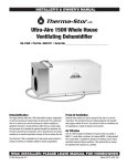
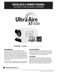
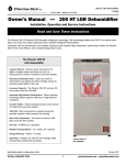
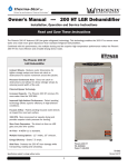
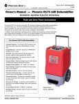
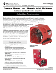
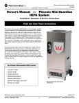
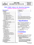
PO Box 8680 • Madison, WI 53708
Phoenix 300 High Capacity Dehumidifier
Part number TS-218
Owner’s Manual — Phoenix 300
Installation, Operation and Service Instructions
Read and Save These Instructions
The Phoenix 300 Dehumidifier is designed to maximize the water removal capacity from a single 110V, 15 amp circuit.
The multiple ducting options on the Phoenix 300 allows for ducting both the intake air and the filtered and
dehumidified supply air. This makes it possible to easily combine the Phoenix 300 with a HEPA air scrubber, air
conditioner or desiccant dehumidifier.
Phoenix dehumidifiers feature significant air filtration. Even the standard 57% MERV-8 filters remove over 90% of
seven-micron particles (the size of a human red blood cell). This filtration dramatically improves the air quality in the
areas being dried and assures continued optimal performance of the refrigeration system.
The Phoenix 300
High Capacity Dehumidifier
High capacity – Up to 38 gallons per day
High energy efficiency – Plugs into a grounded 115V
outlet
Pleated media filter – Built-in air filter reduces dust
and mold
Twist-on duct collar – Direct the drying power where
you need it
Optional high-efficiency filter – Removes 95% of
one-micron particles
Reservoir pump system – Strong and dependable,
20 ft of lift
Pump purge switch – Drains reservoir, no spills or
drips
Pump fail warning light and cut-off – Prevents reservoir
overflow
Lighted power switch – Check machine status at a
glance
Digital hour meter – Easy-to-read for more accurate
billing
Phoenix 300
PN 4022599
30-ft power cord – No need for extension cords
30-ft drain hose – Pump condensate to sinks or drains
Revised 1/07
Specifications subject to change without notice.
Toll-Free 1-800-533-7533
www.thermastor.com • [email protected]
1 Specifications
Table of Contents
Introduction.................................................................1
1. Specifications.........................................................2
2. Operation..............................................................2
2.1 Transporting the Phoenix 300...........................2
2.2 Location.........................................................2
2.3 Electrical Requirements...................................2
2.4 Condensate Removal.......................................3
2.5 Ducting...........................................................3
2.6 Power Switch..................................................3
2.7 Pump Purge Switch..........................................3
2.8 Pump Fail Light...............................................3
2.9 Hour Meter.....................................................3
2.10 Defrost Control Adjustment.............................3
2.11 Low Pressure Control......................................4
3. Maintenance..........................................................4
3.1 Air Filter..........................................................4
3.2 Blower Oiling...................................................4
3.3 Storage..........................................................4
4. Service..................................................................4
4.1 Warranty.........................................................4
4.2 Technical description.......................................4
4.3 Troubleshooting...............................................5
4.4 Refrigerant Charging........................................6
4.5 Blower Replacement........................................6
4.6 Compressor/Capacitor Replacement................6
4.6A Checking Compressor Motor Circuits..........6
4.6B Replacing a Burned Out Compressor..........6
4.6C Replacing a Compressor- Non-Burn Out.......7
4.7 Defrost Thermostat and Timer..........................7
4.8 Condensate Pump...........................................7
4.9 Relay..............................................................8
4.10 Time Delay.....................................................8
5. Wiring Diagram......................................................8
6. Service Parts List...................................................9
7. Warranty..............................................................11
Part No.
Power12 amps, 115 Vac, Grounded
Water
Removal
176 pints/day @ AHAM 80°F, 60% RH
304 pints/day maximum @ 90°F, 90% RH
Blower
540 CFM without external ducting
Refrigerant
Charge
Optional Duct
Connection
Drain Hose
Condensate
Pump
2 lbs., 5 oz. R-22
Operating Temp Range
33°F to 105°F
Warranty
Five Years;
First year 100% of Parts and Labor
Second-fifth year 100% of Parts of Sealed Refrigeration System
10” round outlet
30’ Vinyl
Internal, w/20’ Lift
Dimensions
Width
Cabinet
Overall
Shipping
24”
29”
30”
Height 45”
46”
54”
Depth
20” 25”
28”
Weight175 Lbs
210 Lbs
2 Operation
2.1 Transporting the Phoenix
The Phoenix 300 must always be upright when transported
by vehicle. It may be tipped on to its handle and back for
loading and moving by hand.
2.2 Location
Note the following precautions when locating the Phoenix
300:
• It is designed to be used INDOORS ONLY.
• If used in a wet area, plug it into a GROUND FAULT
INTERRUPTER.
• DO NOT use the Phoenix 300 as a bench or table.
• It must always be used in the upright position.
• The air inlet on top and the side outlet must be at least
1 foot from walls and other obstructions to air flow.
• If the humid area is very large, dehumidification can
be improved by adding an outlet duct to circulate air to
stagnant areas (see Sec. 2.5).
Serial No. ___________________________
Purchase Date ______/______/_____
Dealer’s Name ___________________________________
Read the operation and maintenance instructions
carefully before using this unit. Proper adherence to these
instructions is essential to obtain maximum benefit from
your Phoenix 300 dehumidifier.
Toll-Free 1-800-533-7533
4022599
www.thermastor.com • [email protected]
2.3 Electrical Requirements
2.8 Pump Fail Light
The Phoenix 300 can be plugged into a grounded 15 Amp
circuit. At 80°F, 60% RH, it draws 11.e Amps. Due to the
high percentage of a 15 Amp circuit’s capacity that the
unit uses, the circuit should be dedicated to running it
only. Amp draw decreases at lower loads and increases
at higher loads. At extremely high loads, a 20 Amp circuit
may be required.
The unit briefly draws more amps to start if it has been
stored in a cold area. This may cause a 15 Amp circuit
breaker to trip. A 20 Amp circuit is recommended in such
situations. Some models have a time delay to delay the
compressor start about 2 minutes after the power switch
is turned on. This reduces the unit’s starting amp draw by
starting the blower and compressor at different times.
If an extension cord is required, it must have a minimum of
12 gauge conductors if 25 feet long or less and 10 gauge
conductors if greater than 25 feet long.
If the condensate pump fails, water draining into the pump
reservoir will fill above its normal level. A safety float
switch will then turn on the pump fail light (located next
to the pump purge switch) and stop the compressor. This
prevents water from overflowing and wetting the floor. The
safety switch will not allow the compressor to restart until
water has been removed from the pump reservoir.
2.9 Hour Meter
The digital hour meter measures the cumulative time that
the unit is turned on to tenths of an hour. It stores its
total when the unit is unplugged; the previous total will be
displayed when the unit is next turned on. It resets to zero
after 99,999.9 hours of operation.
2.10 Defrost Control Adjustment
When the Phoenix 300 is used in a cool area, frost will
form on the cooling coil as it dehumidifies. When enough
frost forms, the defrost thermostat will initiate the
timed defrost cycle. The cycle periodically turns off the
compressor while allowing the blower to run. The frost is
melted by the air that the blower draws through the cooling
coil.
The defrost cycle is automatic and designed for optimum
performance above 50°F. If the unit is used in an area that
is below 50°F for more than 2 hours, adjustment of the
defrost timer is recommended to improve performance
(see Sec. 2.10).
2.4 Condensate Removal
The Phoenix 300 is equipped with an internal condensate
pump to remove the water that is condensed during
dehumidification. This allows the condensate to be
pumped 30’ with the attached hose. If the condensate
must be pumped more than 20 feet above the unit, a
second pump must be added to relay the condensate.
2.5 Ducting
A detachable 10” round exhaust collar is supplied that
will allow a 10” round flexible duct to be attached to the
Phoenix 300 outlet. The duct and collar may be quickly
attached to the Phoenix 300 by sliding the 4 collar tabs
into the slots around the blower outlet and rotating the
collar clockwise. It may be quickly removed to transport
the unit more easily.
DRYING TIP: Air’s ability to absorb moisture from wet
surroundings and the Phoenix 300’s ability to remove
moisture from that air is greatly improved at higher
temperatures. We recommend that the area to be dried be
heated to over 70°F if possible. Less drying time will be
required and efficiency will improve.
2.6 Power Switch
To adjust the defrost timer:
1. Unplug the unit.
2. Remove the front cover (6 screws).
3. The timer is fastened to the right inside panel. Every
fourth peg around the dial is pushed out from the dial
center except one section with 5 pegs out in a row.
See figure 1. Each fourth “out” peg represents 15
minutes of compressor “off” time during every hour
that the unit is in the defrost cycle.
4. To improve performance below 50°F, the compressor
“off” time must be increased to 30 minutes per hour
to allow the frost to completely melt. To do this, push
the pegs out from the dial center so that the pegs
alternate with 2 toward the center, then 2 out from
the center, all the way around the dial except for the
section now with 6 pegs out in a row (see Fig. 1).
The power switch (on left side of hour meter) lights up
when the unit is turned on. The unit will continue to run
in all conditions until the switch is turned off; there is no
dehumidistat.
2.7 Pump Purge Switch
This switch (on right side of hour meter) minimizes the
water left in the condensate pump reservoir for moving or
storage. Pressing and holding the pump purge switch will
cause the condensate pump to run. Hold the switch in
until the flow from the condensate hose stops.
Toll-Free 1-800-533-7533
www.thermastor.com • [email protected]
3.3 Storage
5. Replace the cover.
Change the timer pegs back to the original pattern for use
above 50°F.
Above 50°F
There are two issues to consider when the Phoenix 300 is
stored between uses and both pertain to the water trapped
in the unit: damage caused by freezing and biological
growth. The effect of the trapped water can be greatly
reduced if precautions are taken to remove as much as
possible before storage.
1. Use the pump purge switch (see Sec. 2.7 and Fig. 3)
to reduce the water level in the reservoir.
2. Stretch the hose flat to drain it completely.
If the unit will not be exposed to freezing temperatures,
an alternative way to reduce biological growth is to flush
the unit with a bio-fungicide that is approved for use with
copper, aluminum and polyethylene. To flush:
1. Run the hose to a drain.
2. Plug in the unit but do not turn it on.
3. Remove the air filter. Slowly pour a quart of the
chemical through the top grille so that it drains into
the white plastic slots.
4. Hold in the pump purge switch to reduce the water
level in the reservoir.
Below 50°F
Figure 1: Defrost Control Timer
2.11 Low Pressure Control
If the low side refrigerant pressure drops to 15 PSIG, the
low pressure control opens and shuts off the compressor
and blower. It is an automatically reset control. Its primary
function is to prevent damage to the compressor if a leak
develops in the refrigeration system. It may also open if
the unit is A) used in a cool area (below 50°F) and the
defrost timer is not adjusted (see Sec. 2.10) or B) stored
where it is below 40°F and then started. Under these
conditions, the unit will restart within several minutes.
Until the unit warms up, it may cycle several times.
4 Service
CAUTION: Servicing the Phoenix 300 with its high pressure
refrigerant system and high voltage circuitry presents a
health hazard that could result in death, serious bodily
injury, and/or property damage. Only qualified service
people should service this unit.
3 Maintenance
3.1 Air Filter
The Phoenix 300 is equipped with MERV-8 pleated fabric
air filter that must be checked regularly. Operating the unit
with a dirty filter will reduce the dehumidifier’s capacity and
efficiency and may cause the compressor to cycle off and
on unnecessarily on the defrost control.
Two optional filters are available: A) a 2” pleated filter that
has the same efficiency as the 4” standard filter, but less
surface area. This filter would need to be changed more
often than the 2” version. B) a 95% efficient 4” filter that
acts as an air scrubber to catch mold and mildew spores.
The filter can generally be vacuumed clean several times
before needing replacement. Replacement filters can be
ordered from the factory or purchased locally if available.
DO NOT operate the unit without the filter or with a less
effective filter as the heat exchange coils inside the unit
could become clogged and require disassembly to clean.
4.1 Warranty
A warranty certificate has been enclosed with this unit;
read it before any repair is initiated.
If a warranty repair is required, call the factory first at
1-800-533-7533 for warranty claim authorization and
technical assistance.
4.2 Technical Description
The Phoenix 300 uses a refrigeration system similar to
an air conditioner’s to remove heat and moisture from
incoming air, and to add heat to the air that is discharged
(see Fig. 2).
Hot, high pressure refrigerant gas is routed from the
compressor to the condenser coil (see Figure 2). The
refrigerant is cooled and condensed by giving up its heat
to the air that is about to be discharged from the unit.
The refrigerant liquid then passes through a filter/drier
and capillary tubing which cause the refrigerant pressure
and temperature to drop. It next enters the evaporator
3.2 Blower Oiling
The blower motor is lubricated for life from the factory and
does not require oiling by the owner.
Toll-Free 1-800-533-7533
www.thermastor.com • [email protected]
coil where it absorbs heat from the incoming air and
evaporates.
5. Defective compressor (Sec. 4.6).
6. Defective relay (Sec. 4.9).
7. Defective time delay (Sec. 4.10).
No dehumidification. Blower runs but compressor does not.
Pump fail light not lit.
1. Bad connection in compressor circuit (Fig. 3).
2. Defective compressor capacitor (Sec. 4.6A).
3. Defective compressor overload (Sec. 4.6A).
4. Defective compressor (Sec. 4.6).
5. Defective relay (Sec. 4.9).
6. Defective time delay (Sec. 4.10).
No dehumidification. Pump Fail Light lit. Blower runs but
not compressor.
1. Bad connection in pump circuit (Fig. 3).
2. Pump float switch or safety switch defective (Sec. 4.8).
3. Pump motor defective (Sec. 4.8).
Figure 2: Refrigeration system of Phoenix
The evaporator operates in a flooded condition, which
means that all the evaporator tubes contain liquid
refrigerant during normal operation. A flooded evaporator
should maintain constant pressure and temperature
across the entire coil, from inlet to outlet.
The mixture of gas and liquid refrigerant enter the
accumulator after leaving the evaporator coil. The
accumulator prevents any liquid refrigerant from reaching
the compressor. The compressor evacuates the cool
refrigerant gas from the accumulator and compresses it to
a high pressure and temperature to repeat the process.
Blower does not run. Compressor runs briefly but cycles on
and off.
1. Loose connection in blower circuit (Fig. 3).
2. Obstruction prevents impeller rotation.
3. Defective blower (Sec. 4.5).
Unit removes some water but not as much as expected.
1. Air temperature and/or humidity have dropped.
2. Humidity meter and/or thermometer used are out of
calibration.
3. Unit has entered defrost cycle (Sec. 2.10 and 4.7).
4. Air filter dirty (Sec. 3.1).
5. Defrost timer incorrectly set for conditions (Sec. 2.10
and 4.7).
6. Defective defrost thermostat (Sec. 4.7)
7. Low refrigerant charge (Sec. 4.4).
8. Air leak such as loose cover.
9. Defective compressor (Sec. 4.6).
10.Restrictive exhaust ducting (Sec. 2.5)
4.3 Troubleshooting
No dehumidification. Neither blower or compressor run.
Power switch does not light when ON.
1. Unit unplugged or no power to outlet.
2. Power switch defective (Sec. 2.6).
3. Loose connection in internal wiring (Fig. 3).
No dehumidification. Neither blower or compressor run.
Power switch ON and lit.
1. Low pressure control open (Sec. 2.11).
2. Power switch defective (Sec. 2.6).
3. Loose connection in internal wiring (Fig. 3).
Unit runs but does not pump water.
1. Hose kinked or plugged.
2. Pump check valve plugged (Sec. 4.8).
3. Bad connection in pump circuit (Fig. 3).
4. Hose disconnected internally.
Some dehumidification, blower runs continuously but
compressor only runs sporadically.
1. Unit is in defrost cycle (Sec. 2.10 and 4.7).
2. Defrost thermostat defective or loose
(Sec. 2.10 and 4.7).
3. Loose connection in compressor circuit
(see Fig. 3).
4. Defective compressor overload (Sec. 4.6A).
Toll-Free 1-800-533-7533
Unit pumps water automatically but not when purge switch
is pushed.
1. Bad connection in purge switch circuit (Fig. 3).
2. Defective purge switch (Sec. 2.7).
www.thermastor.com • [email protected]
4.6A Checking Compressor Motor Circuits
Perform the following tests if the blower runs but the
compressor does not with the power switch ON.
1. Turn the power switch OFF and unplug the unit, remove
the cabinet front (6 screws).
2. Plug in the unit and turn the power switch ON. Use
a voltmeter to check for 110 to 120 volts between
(a) the relay terminal that the black wire from the
compressor connects to and (b) the capacitor terminal
with the (3) white wires and (1) red wire connected.
If voltage is present, go to step 3. If no voltage, the
low pressure control, the time delay or the relay are
open or there is a loose connection in the compressor
circuit. Test each component for continuity; see the
appropriate section if a defect is suspected.
3. Turn the power switch OFF and unplug the unit, then
disconnect the red and yellow wires from compressor
terminals R and S. Using an ohmmeter, check
continuity between the points listed below.
4. Compressor terminals C and S: No continuity indicates
an open start winding; the compressor must be
replaced.
5. Compressor terminals C and R: No continuity indicates
an open run winding; the compressor must be
replaced.
6. Compressor terminal C and overload terminal 1: No
continuity indicates a defective overload lead.
7. Overload terminals 1 and 3: If there is no continuity,
the overload may be tripped; wait 10 minutes and try
again. If there is still no continuity, it is defective and
must be replaced.
8. Compressor terminal C and compressor case:
Continuity indicates a grounded motor; the compressor
must be replaced.
9. Disconnect the wires from the capacitor. Set the
ohmmeter to the Rx1 scale; the capacitor is shorted
and must be replaced if continuity exists across its
terminals. If there is no needle movement with the
meter set on the Rx100000 scale, the capacitor is
open and must be replaced.
10. Reconnect the wires to the compressor and capacitor;
plug in and turn on the unit. If the compressor fails to
start, replace the run capacitor.
11. If the unit still does not start, adding a hard-start kit
will provide greater starting torque. If this does not
work, the compressor has an internal mechanical
defect and must be replaced.
Evaporator coil frosted continuously, low dehumidifying
capacity.
1. Defrost thermostat loose or defective
(Sec. 2.10 and 4.7).
2. Defrost timer incorrectly set or defective
(Sec. 2.10 and 4.7).
2. Low refrigerant charge (Sec. 4.4).
3. Dirty air filter or air flow restricted. (Sec. 3.1).
Compressor runs with power switch OFF.
1. Defective relay (Sec. 4.10).
2. Defective power switch (Sec. 2.6)
4.4 Refrigerant Charging
If the refrigerant charge is lost, a new charge must be
accurately weighed in. If any of the old charge is left in the
system, it must be removed before weighing in the new
charge. Refer to the unit nameplate for the correct charge
weight and refrigerant type.
4.5 Blower Replacement
The centrifugal blower has a PSC motor and internal
thermal overload protection. If defective, the complete
assembly must be replaced.
1. Unplug the power cord.
2. Remove the cabinet front (6 screws).
3. Disconnect the blower leads.
4. Pull the oil tubes out of the motor.
5. Tip the unit on its back. From the bottom, remove the
2 screws that fasten the blower housing to the base.
6. Remove the four screws holding the blower outlet
flange to the cabinet end.
7. Remove the blower. Use care to avoid hooking wiring,
tubing or electrical components.
8. Reassembling with the new blower is the above
procedure reversed.
4.6 Compressor/Capacitor Replacement
This compressor is equipped with a two terminal external
overload, run capacitor, but no start capacitor or relay (see
Fig. 3).
CAUTION-ELECTRICAL SHOCK HAZARD: Electrical power
must be present to perform some tests; these tests should
be performed by a qualified service person.
Toll-Free 1-800-533-7533
4.6B Replacing a Burned Out Compressor
The refrigerant and oil mixture in a compressor is
chemically very stable under normal operating conditions.
However, when an electrical short occurs in the
compressor motor, the resulting high temperature arc
causes a portion of the refrigerant oil mixture to break
down into carbonaceous sludge, a very corrosive acid,
www.thermastor.com • [email protected]
and water. These contaminants must be carefully removed
otherwise even small residues will attack replacement
compressor motors and cause failures.
The following procedure is effective only if the system is
monitored after replacing the compressor to insure that
the clean up was complete.
1. This procedure assumes that the previously listed
compressor motor circuit tests revealed a shorted or
open winding. If so, cautiously smell the refrigerant
from the compressor service port for the acid odor of
a burn out.
running burn out has occurred, several filter/driers
may have to be replaced to remove all of the acid and
moisture.
NOTE: NEVER use the compressor to evacuate the system
or any part of it.
WARNING: The gas could be toxic and highly acidic. If no
acid odor is present, skip down to the section on changing
a non-burn out compressor.
4.7 Defrost Thermostat and Timer
4.6C Replacing a Compressor- Non-Burn Out
Remove the refrigerant from the system. Replace the
compressor and liquid line filter/drier. Charge the system
to 50 PSIG and check for leaks. Remove the charge and
weigh in the refrigerant quantity listed on the nameplate.
Operate the system to verify performance.
The defrost thermostat is attached to the refrigerant
suction tube between the accumulator and compressor.
If the low side refrigerant temperature drops due to
excessive frost formation on the evaporator coil, the
thermostat opens. The compressor is then cycled off and
on by the defrost timer. The blower will continue to run,
causing air to flow through the evaporator coil and melt the
ice when the compressor is off. When the air temperature
and/or humidity increase, the evaporator temperature will
rise and the thermostat will close to end the defrost cycle.
To improve performance in low temperatures, see Sec. 2.9
for defrost timer adjustment.
2. Remove and properly dispose of the system charge.
DO NOT vent the refrigerant or allow it to contact your
eyes or skin.
3. Remove the burned out compressor. Use rubber gloves
if there is any possibility of coming in contact with the
oil or sludge.
4. To facilitate subsequent steps, determine the type of
burn out that occurred. If the discharge line shows no
evidence of sludge and the suction line is also clean
or perhaps has some light carbon deposits, the burn
out occurred while the compressor was not rotating.
Contaminants are therefore largely confined to the
compressor housing. A single installation of liquid
and suction line filter/driers will probably clean up the
system.
If sludge is evident in the discharge line, it will
likely be found in the suction line; this indicates the
compressor burned out will running. Sludge and acid
have been pumped throughout the system. Several
changes of the liquid and suction filter/driers will
probably be necessary to cleanse the system.
5. Correct the system fault that caused the burn out.
Consult the factory for advice.
6. Install the replacement compressor with a new
capacitor and an oversized liquid line filter.
In a running burn out, install an oversized suction line
filter/drier between the accumulator and compressor.
Thoroughly flush the accumulator with refrigerant to
remove all trapped sludge and to prevent the oil hole
from becoming plugged. A standing burn out does not
require a suction line filter/drier.
7. Evacuate the system with a good vacuum pump and
accurate vacuum gauge. Leave the pump on the
system for at least an hour.
8. Operate the system for a short period of time,
monitoring the suction pressure to determine that the
suction filter is not becoming plugged. Replace the
suction filter/drier if pressure drop occurs. If a severe
Toll-Free 1-800-533-7533
4.8 Condensate Pump
Condensate is automatically pumped when the water level
in the pump’s reservoir rises to close the float switch or if
the pump purge switch is held in.
If the pump is unable to empty its reservoir due to a
pump failure or blocked condensate hose, a pump safety
float switch is triggered before the reservoir overflows.
The switch turns on the pump fail light and turns off the
compressor via its relay.
To replace the condensate pump:
1. Unplug the unit and remove the front cover.
2. Disconnect the 2 hoses from the pump.
3. Cut the pump lead wires near the old pump.
4. Remove the 4 screws from the unit bottom that hold
the pump to the base.
5. Attach the new pump with 4 screws.
6. Connect the new pump wiring. It may be easier to
splice the new and old gray leads together with a wire
nut, and splice the new and old yellow leads together,
rather than route the new ones to the pump purge
switch and pump fail light.
7. Connect the hoses to the new pump. Carefully
route the hoses so they do not contact the copper
refrigerant lines or the compressor shell.
www.thermastor.com • [email protected]
4.9 Relay
4.10 Time Delay (HP model only)
The contacts of the single pole, single throw relay
complete the power circuit to the compressor. The
contacts are closed when power is provided to the relay
coil via the control circuit. The control circuit includes the
power switch, low pressure control, time delay (HP model),
defrost thermostat and timer.
The HP model has a time delay relay in the compressor
control circuit. This relay delays the compressor start
about 2 minutes after the power switch is turned on.
This reduces the unit’s starting amp draw by starting the
blower and compressor at different times. This reduces
the chance of tripping a circuit breaker during hard start
situations, such as when the unit has been stored in a
cold place. It also reduces compressor short cycling after
the compressor has stopped.
5 Wiring Diagram
Figure 3: Electrical schematic of Phoenix 300
Toll-Free 1-800-533-7533
www.thermastor.com • [email protected]
6 Service Parts
Description
Items listed are not shown
40218181
Accumulator
40226361
Air Filter, Pleated, 2” x 20” x 20”
40225971
40219501
Wiring Diagram (on Cover)
(not shown)
Ground Fault Interrupter
(optional)
40230791
Coupling, Body,
Quick Connect, .38 Tube
40230801
Coupling, Insert,
Quick Connect,.38 Tube
Item Part No.
1
2
Qty.
40226141
Air Filter, Pleated, 4” x 20” x 20” MERV-8
40226241
Air Filter, Pleated, 4” x 20” x 20” (90-95% EFFICIENT)
3
40210831
Blower w/ Capacitor
4
4022622
2
Bumper, Foot, 1.50 Dia. x .75 High
5
4017777
2
Capillary Tubes, .059” ID x .124” OD x 32” long
6
40225631
Coil, Condenser
7
40225571
Coil, Evaporator
8
40226001
Compressor, Carlyle
(P/N EBA135111A)(HP Model)
40236451
Compressor Kit, Carlyle
(P/N EBA120111A) (4022750 Compressor only)
9
40225951
Compressor Overload, Carlyle (included with compressor)
10
40226341
Condensate Pump
11
40226151
Cord and Wire Harness
2
1
7
24
26
6
14
18
12
40219081
Drain Hose
(.38 ID x .56 OD x 33’ long)
13
40226111
Outlet Collar (for Ducting Outlet)
14
40225931
Filter/Drier (not shown)
15
40215971
Hour Meter
16
40210891
Indicator Light, Red, 125V
17
40226161
Instruction Label (not shown)
18
40222191
Low Pressure Control
17
1919700101
Relay
15
20
40227401
Run Capacitor, 30 MFD, 370V
22
21
4021997
Spring
22
40217961
Switch, Pump Purge
23
40218221
Switch, Power
24
40214701
Thermostat, Defrost
40216481
Thermostat, Defrost,
Mounting Clip
25
40218231
Timer, Defrost
26
40228781
Time Delay (HP Model)
27
4022613
Wheel, 12”, Plastic
6
2
8
9
10
3
23
16
11
12
13
25
27
19
20
4
Toll-Free 1-800-533-7533
26
Specifications subject to change without notice.
www.thermastor.com • [email protected]
This page intentionally left blank.
Toll-Free 1-800-533-7533
10
www.thermastor.com • [email protected]
Phoenix 300 Dehumidifier Limited Warranty
Warrantor:
Therma-Stor LLC
PO Box 8680
Madison, WI 53708
Telephone: 1-800-533-7533
Who Is Covered: This warranty extends only to the original end-user of the Phoenix 300
dehumidifier, and may not be assigned or transferred.
First Year Warranty Therma-Stor LLC warrants that, for one (1) year the Phoenix 300 dehumidifier
will operate free from any defects in materials and workmanship, or Therma-Stor LLC will, at its
option, repair or replace the defective part(s), free of any charge.
Second Through Fifth Year Warranty: Therma-Stor LLC further warrants that for a period of five (5)
years, the condenser, evaporator, and compressor of the Phoenix 300 dehumidifier will operate
free of any defects in material or workmanship, or Therma-Stor LLC, at its option, will repair or
replace the defective part(s), provided that all labor and transportation charges for the part(s)
shall be borne by the end-user.
End-User Responsibilities: Warranty service must be performed by a Servicer authorized
by Therma-Stor LLC. If the end-user is unable to locate or obtain warranty service from an
authorized Servicer, he should call Therma-Stor LLC at the above number and ask for the ThermaStor Service Department, which will then arrange for covered warranty service. Warranty service
will be performed during normal working hours.
The end-user must present proof of purchase (lease) upon request, by use of the warranty
card or other reasonable and reliable means. The end-user is responsible for normal care.
This warranty does not cover any defect, malfunction, etc. resulting from misuse, abuse, lack
of normal care, corrosion, freezing, tampering, modification, unauthorized or improper repair or
installation, accident, acts of nature or any other cause beyond Therma-Stor LLC’s reasonable
control.
Limitations and Exclusions: If any Phoenix 300 Dehumidifier part is repaired or replaced, the new
part shall be warranted for only the remainder of the original warranty period applicable thereto
(but all warranty periods will be extended by the period of time, if any, that the Phoenix 300
Dehumidifier is out of service while awaiting covered warranty service).
UPON THE EXPIRATION OF THE WRITTEN WARRANTY APPLICABLE TO THE PHOENIX 300
DEHUMIDIFIER OR ANY PART THEREOF, ALL OTHER WARRANTIES IMPLIED BY LAW, INCLUDING
MERCHANTABILITY AND FITNESS FOR A PARTICULAR PURPOSE, SHALL ALSO EXPIRE. ALL
WARRANTIES MADE BY THERMA-STOR LLC ARE SET FORTH HEREIN, AND NO CLAIM MAY
BE MADE AGAINST THERMA-STOR LLC BASED ON ANY ORAL WARRANTY. IN NO EVENT
SHALL THERMA-STOR LLC, IN CONNECTION WITH THE SALE, INSTALLATION, USE, REPAIR OR
REPLACEMENT OF ANY PHOENIX 300 DEHUMIDIFIER OR PART THEREOF BE LIABLE UNDER
ANY LEGAL THEORY FOR ANY SPECIAL, INDIRECT OR CONSEQUENTIAL DAMAGES INCLUDING
WITHOUT LIMITATION WATER DAMAGE (THE END-USER SHOULD TAKE PRECAUTIONS AGAINST
SAME), LOST PROFITS, DELAY, OR LOSS OF USE OR DAMAGE TO ANY REAL OR PERSONAL
PROPERTY.
Some states do not allow limitations on how long an implied warranty lasts, and some do not
allow the exclusion or limitation of incidental or consequential damages, so one or both of these
limitation may not apply to you.
Toll-Free 1-800-533-7533
11
www.thermastor.com • [email protected]