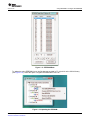
1
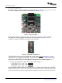
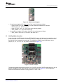
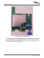
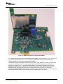
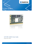
SLLU108 – July 2008
XIO3130 EVM
1.1
Overview
The Texas Instruments XIO3130 EVM is a functional implementation of a four-port PCIe-to-PCIe switch.
The XIO3130 EVM was designed to allow validation of three separate functional modes. In normal mode,
the EVM is configured as a generic PCI Express (PCIe) switch. In hot-plug mode, downstream ports 1 and
2 are configured as hot-pluggable slots. In ExpressCard mode, all three downstream ports are configured
to support the ExpressCard adapter board. The different functional modes are discussed later in this
document.
Figure 1-1 shows the EVM board. There are various jumpers, dipswitches, push buttons, and LEDs to
support the various functional modes. For the board to operate, power must be applied via the peripheral
power connector located to the right side of the board. Endpoints can be plugged directly into any one or
all of the downstream ports. The upstream edge connector can be plugged into any PCIe slot on a
motherboard. Once the EVM with attached endpoints is plugged into a PCIe motherboard and power is
provided to the EVM, nothing else needs to be done in order for the EVM to operate. The two LEDs in the
upper right-hand corner light up when power is applied to the peripheral power connector.
Figure 1-1. EVM Board
SLLU108 – July 2008
Submit Documentation Feedback
XIO3130 EVM
1
Normal-Mode Operation
1.2
www.ti.com
Normal-Mode Operation
By default, the EVM should be configured to operate in normal mode. The six jumpers (J7, J11, J13, J14,
J15, and J16) should be covering both pins of each header (see Figure 1-2).
Figure 1-2. Power Jumpers
The dipswitch should be configured with SCL slide switch in the up position and DN1_DPSTRP,
DN2_DPSTRP, and DN3_DPSTRP slide switches in the down position (see Figure 1-3). This
configuration enables the EEPROM and disables hot-plug operation.
Figure 1-3. Dipswitch Configuration
The EEPROM (U3) should also be preconfigured for normal-mode operation. See Section 1.5 for an
explanation of how to configure the EEPROM. Upon deassertion of PERST, the XIO3130 automatically
reads data from the EEPROM. This data is used to preset various PCI configuration register bits. For
normal-mode operation, the data in the EEPROM will configure bits in the following registers:
• GPIO C control register (PCI register offset: C0h in upstream bridge)
– PCIE_GPIO12_CTL = 010b – Port 1 ACT_LED0
– PCIE_GPIO13_CTL = 011b – Port 2 ACT_LED1
– PCIE_GPIO14_CTL = 100b – Port 3 ACT_LED2
Setting these bits configures LED1 as activity LED for port 1, LED2 as activity LED for port 2, and LED3
as activity LED for port 3. Any time a TLP is transferred to or from the slot, the activity LED flashes. LEDs
4 and 5 are nonfunctional in normal mode; pressing the push buttons will have no effect on the XIO3130.
2
XIO3130 EVM
SLLU108 – July 2008
Submit Documentation Feedback
Hot-Plug-Mode Operation
www.ti.com
Figure 1-4. GPIO Control Register
•
•
1.3
General control register (PCI register offset: D4h in each downstream bridge)
– RCVR_PRSNT_EN = 0b – PRSNT pin is used to determine whether slot is present
– REFCK_DIS = 0b – REFCK enabled
– LINK_ACT_RPT_CAP = 1b – Slot is link active reporting capable
– SLOT_PRSNT = 1b – Port connected to slot
General slot info register (PCI register offset EEh in each downstream bridge)
– SLOT_NUM = 1b for slot 1, 2b for slot 2, and 3b for slot 3
Hot-Plug-Mode Operation
In hot-plug mode, the EVM board utilizes the TPS2363 PCIe server dual-slot hot-plug controller to switch
power on and off to slots 1 and 2. The TPS2363 is directly controlled by the hot-plug controller built into
the XIO3130. Slot 3 operates in normal mode. To configure the EVM for hot-plug operation, the six
jumpers (J7, J11, J13, J14, J15, J16) must be removed (see Figure 1-5).
Figure 1-5. Power Jumpers
The dipswitch should be configured with SCL, DN1_DPSTRP and DN2_DPSTRP slide switches in the up
position, and DN3_DPSTRP slide switches in the down position (see Figure 1-6). This configuration
enables the EEPROM and enables hot-plug operation on slots 1 and 2.
SLLU108 – July 2008
Submit Documentation Feedback
XIO3130 EVM
3
Hot-Plug-Mode Operation
www.ti.com
Figure 1-6. Dipswitch Configuration
The EEPROM (U3) should be reconfigured for hot-plug-mode operation. See Section 1.5 for an
explanation of how to configure the EEPROM. Upon deassertion of PERST, the XIO3130 automatically
reads data from the EEPROM. This data is used to preset various PCI configuration register bits. For
hot-plug-mode operation, the data in the EEPROM configures bits in the following registers:
• GPIO B control register (PCI Register offset: BEh in upstream bridge)
– PCIE_GPIO8_CTL = 010b – Port 1 ACT_BTN0
– PCIE_GPIO9_CTL = 100b – Port 1 ATN_LED0
• GPIO C control register (PCI register offset: C0h in upstream bridge)
– PCIE_GPIO10_CTL = 011b –Port 2 ACT_BTN1
– PCIE_GPIO11_CTL = 101b – Port 2 PWRFLT1
– PCIE_GPIO12_CTL = 101b – Port 1 PWR_LED0
– PCIE_GPIO13_CTL = 110b – Port 2 PWR_LED1
• GPIO D control register (PCI register offset: C2h in upstream bridge)
– PCIE_GPIO15_CTL = 101b – Port 1 PWRFLT0
– PCIE_GPIO16_CTL = 011b – Port 2 ATN_LED1
Setting these bits configures LED1 as PWR_LED0 for port 1 and LED2 as PWR_LED1 for port 2. LED3 is
not used in hot-plug mode. LEDs 4 will be configured as ATN_LED0 for port 1 and LED5 will be
configured as ATN_LED1 for port 2. Push-button switch SW2 is the attention button for port 1 and SW3 is
the attention button for port 2.
Figure 1-7. GPIO Control Register
4
XIO3130 EVM
SLLU108 – July 2008
Submit Documentation Feedback
ExpressCard-Mode operation
www.ti.com
•
•
•
1.4
General control register (PCI register offset: D4h in port 1 and port 2 downstream bridges)
– RCVR_PRSNT_EN = 0b – PRSNT pin is used to determine whether slot is present
– REFCK_DIS = 0b – REFCK enabled
– LINK_ACT_RPT_CAP = 1b – Slot is link active reporting capable
– SLOT_PFIP = 1b – Power fault input implemented
– SLOT_PRSNT = 1b – Port connected to slot
– SLOT_ABP = 1b – Attention button implemented
– SLOT_PCP = 1b – Power controller implemented
– SLOT_AIP = 1b – Attention indicator implemented
– SLOT_PIP = 1b – Power indicator implemented
– SLOT_HPS = 1b – Device present that can be removed without prior notification.
– SLOT_HPC = 1b – Slot is hot-plug capable
– RC_PF_CTL = 1b – REFCK output enable is a function of PWR_FAULT
General control register (PCI register offset: D4h in port 3 downstream bridge)
– RCVR_PRSNT_EN = 0b – PRSNT pin is used to determine whether slot is present
– REFCK_DIS = 0b – REFCK enabled
– LINK_ACT_RPT_CAP = 1b – Slot is link active reporting capable
– SLOT_PRSNT = 1b – Port connected to slot
General slot info register (PCI register offset EEh in each downstream bridge)
– SLOT_NUM = 1b for slot 1, 2b for slot 2, and 3b for slot 3
ExpressCard-Mode operation
For this mode of operation, the ExpressCard adapter board is used in conjunction with the XIO3130 EVM
board. This adapter board utilizes the TI TPS2231 power interface switch to switch power on and off to the
ExpressCard slot. TI also offers a dual-power interface switch called the TPS2236. Figure 1-8 shows the
adapter board.
SLLU108 – July 2008
Submit Documentation Feedback
XIO3130 EVM
5
ExpressCard-Mode operation
www.ti.com
Figure 1-8. ExpressCard Adapter Board
To configure the XIO3130 EVM for ExpressCard-mode operation, connect the ribbon cable connector from
J1 on the adapter board to one of the matching connectors (J2, J3 or J4) on the XIO3130 EVM board.
Then plug the adapter board into the adjacent PCIe slot as shown in Figure 1-9. It does not matter which
PCIe slot is used, but the ribbon cable must be plugged into the connector just below and to the right of
the PCIe slot that the adapter board is plugged into.
6
XIO3130 EVM
SLLU108 – July 2008
Submit Documentation Feedback
ExpressCard-Mode operation
www.ti.com
Figure 1-9. EVM Configuration for ExpressCard Mode
To configure the XIO3130 EVM for ExpressCard-mode operation, the six jumpers (J7, J11, J13, J14, J15,
J16) must be populated (see Figure 1-5). This routes power directly to slots 1 and 2 bypassing the
TPS2363, which is not required for ExpressCard operation.
The dipswitch should be configured with SCL, DN1_DPSTRP, DN2_DPSTRP, and DN3_DPSTRP slide
switches all in the up position. This configuration enables the EEPROM and enables ExpressCard
operation on all three slots. To use two of the PCIe slots in normal-mode operation and one slot for
ExpressCard operation, two of the DNx_DPSTRP slide switches must be in the down position and the
EEPROM needs to be programmed correctly to support this mode of operation. By default, the
ExpressCard mode EEPROM .dat file is set up to enable ExpressCard-mode operation in any of the PCIe
slots that disables the other non-ExpressCard slots from operating in normal mode.
SLLU108 – July 2008
Submit Documentation Feedback
XIO3130 EVM
7
Using WinROM to Configure the EEPROM
www.ti.com
The EEPROM (U3) will need to be reconfigured for ExpressCard-mode operation. See Section 1.5 for an
explanation of how to configure the EEPROM. Upon deassertion of PERST the XIO3130 will automatically
read data from the EEPROM. This data is used to pre-set various PCI configuration register bits. For
ExpressCard-mode operation the data in the EEPROM will configure bits in the following registers:
• GPIO A control register (PCI register offset: BEh in upstream bridge)
– PCIE_GPIO3_CTL = 010b – Port 1 CLKREQ0
• GPIO B control register (PCI register offset: C0h in upstream bridge)
– PCIE_GPIO7_CTL = 010b – Port 2 CLKREQ1
• GPIO C control register (PCI register offset: C0h in upstream bridge)
– PCIE_GPIO11_CTL = 010b – Port 3 CLKREQ2
– PCIE_GPIO12_CTL = 010b – Port 1 ACT_LED0
– PCIE_GPIO13_CTL = 011b – Port 2 ACT_LED1
– PCIE_GPIO14_CTL = 100b –Port 3 ACT_LED2
Setting these bits configures LED1 as activity LED for port 1, LED2 as activity LED for port2, and LED3 as
activity LED for port 3. Anytime a TLP is transferred to or from the slot, the activity LED will flash. LEDs 4
and 5 are nonfunctional in normal mode; pressing the push buttons has no effect on the XIO3130.
CLKREQ1 and CLKREQ2 are routed across the ribbon cable to the TPS2231.
When plugging in ExpressCards, be careful not to pull the adapter board out of the PCIe socket. Grab a
hold of the upper right-hand corner of the adapter board while sliding the ExpressCard into the socket.
Slide the ExpressCard all the way in until it clicks in place. After releasing the card, it will spring back a
little. To remove the ExpressCard again, grab a hold of the upper right-hand corner of the adapter board,
push the card into the socket until it clicks, and then gently remove the card. The spring will push the card
out of the socket. Do not pull the ExpressCard out of the socket – always push in and let the spring push
the card out.
1.5
Using WinROM to Configure the EEPROM
WinROM is a TI-developed EEPROM programming utility that runs on Windows XP or Vista operating
system. WinROM can be used to program the EEPROM (U3) on the XIO3130 EVM. To use the utility,
install it on the system that contains the XIO3130 EVM. Double click the WinROM icon to start the
program. A dialog box opens that shows all the TI controllers present in the system (see Figure 1-10). The
XIO3130 shows four entries in the bus hierarchy: one entry reads "XIO3130" and the other three entries
read "8322104C." Since the EEPROM is only accessible from the upstream bridge, the three "8233104C"
entries are in red.
Figure 1-10. TI Controllers
To read the data in the EEPROM, double click the XIO3130 entry. A new dialog box opens (see
Figure 1-11). This dialog box allows the user to modify any byte in the EEPROM.
8
XIO3130 EVM
SLLU108 – July 2008
Submit Documentation Feedback
Using WinROM to Configure the EEPROM
www.ti.com
Figure 1-11. EEPROM Data
To update the entire EEPROM from a .dat file that was provided by TI, right click on the XIO3130 entry
(see Figure 1-12). Select the option "Program EEPROM Data From File."
Figure 1-12. Updating the EEPROM
SLLU108 – July 2008
Submit Documentation Feedback
XIO3130 EVM
9
Using WinROM to Configure the EEPROM
www.ti.com
A new dialog box appears that allows the user to select which .dat file to use to program the EEPROM
(see Figure 1-13). Select from one of the three operating modes supplied with the EVM.
Figure 1-13. Selecting a .dat File
After the Open button has been pressed, a new dialog box opens asking if the user is ready for WinROM
to begin flashing the EEPROM. After selecting yes, WinROM starts flashing the EEPROM with the
contents from the file (see Figure 1-13). The .dat files are text documents that can be modified by the
user.
Figure 1-14. Flashing the EEPROM
10
XIO3130 EVM
SLLU108 – July 2008
Submit Documentation Feedback
www.ti.com
Using the TopHAT Utility
Once flashing has completed, the contents of the EEPROM now contains the data from the .dat file.
However, this data is not yet present in the PCI configuration space of the XIO3130. Once flashing has
finished, WinROM displays a dialog box reminding the user to power cycle the system. Power cycling the
system causes the system PERST signal to toggle, at which time the XIO3130 reads the data from the
EEPROM to the PCI configuration registers. Now the XIO3130 is ready to use in the new operating mode.
1.6
Using the TopHAT Utility
TopHAT is a TI-developed utility that allows a user to read or write to various registers in a PCI or PCIe
device. Once the utility has been installed, double click the TopHAT icon to start the program. A dialog
box opens to show the entire PCI bus hierarchy. The XIO3130 will show us as four PCI to PCI bridges.
Look for the TI icon next “PCI/PCI bridge (TI) (see Figure 1-15).
SLLU108 – July 2008
Submit Documentation Feedback
XIO3130 EVM
11
Using the TopHAT Utility
www.ti.com
Figure 1-15. TopHAT
12
XIO3130 EVM
SLLU108 – July 2008
Submit Documentation Feedback
Using the TopHAT Utility
www.ti.com
TopHAT parses the PCI configuration space looking for any capability structure. If it finds a capability
structure, a new icon and description of the capability will show under the device. For example, under the
XIO3130 PCI/PCI bridge (TI) entry, a capability for Power Management Capability Structure is shown with
a PM icon. Double clicking any of the capabilities opens a new dialog box. Some dialog boxes have tabs
that display more information about the capability. Figure 1-16 shows the contents of the “Slot Info” tab for
the PCI Express Capability Structure.
Figure 1-16. Slot Info
In this example, the XIO3130 EVM is operating in hot-plug mode, as can be seen by looking at the Slot
Capabilities table entries. TopHAT can be used to exercise the XIO3130, for example selecting blink from
the Attention Indicator Control drop-down box causes the attention indicator LED on the EVM to blink.
Note that this dialog box also shows where the capability exists in the PCI configuration space. In this
example, it is at offset 0x090. Clicking the “Open Register Access Window” opens the PCI Registers
dialog box (see Figure 1-17). Note that the register where the capability begins is automatically selected,
in this case at PCI offset 0x090.
SLLU108 – July 2008
Submit Documentation Feedback
XIO3130 EVM
13
Using the TopHAT Utility
www.ti.com
Figure 1-17. PCI Registers
Any bit in the PCI configuration space can be modified using the PCI Registers dialog box. A new value
can be directly typed into the “New Value” edit box or entered by pressing any of the bit numbers below
the edit box. The new register value will not be written until the “Write” button is pressed. Note that by
hovering the cursor over the bit numbers a description for the bit appears.
TopHat has many other features. One useful feature is to rescan the PCI bus. For example, while testing
hot plug a user might remove one endpoint device and replace it with another. By pressing the rescan
button, the new device will now be present the PCI hierarchy. To rescan the PCI bus, press the
magnifying glass below the toolbar.
Figure 1-18. TopHAT Features
Trademarks
All trademarks are the property of their respective owners.
14
XIO3130 EVM
SLLU108 – July 2008
Submit Documentation Feedback
EVALUATION BOARD/KIT IMPORTANT NOTICE
Texas Instruments (TI) provides the enclosed product(s) under the following conditions:
This evaluation board/kit is intended for use for ENGINEERING DEVELOPMENT, DEMONSTRATION, OR EVALUATION PURPOSES
ONLY and is not considered by TI to be a finished end-product fit for general consumer use. Persons handling the product(s) must have
electronics training and observe good engineering practice standards. As such, the goods being provided are not intended to be complete
in terms of required design-, marketing-, and/or manufacturing-related protective considerations, including product safety and environmental
measures typically found in end products that incorporate such semiconductor components or circuit boards. This evaluation board/kit does
not fall within the scope of the European Union directives regarding electromagnetic compatibility, restricted substances (RoHS), recycling
(WEEE), FCC, CE or UL, and therefore may not meet the technical requirements of these directives or other related directives.
Should this evaluation board/kit not meet the specifications indicated in the User’s Guide, the board/kit may be returned within 30 days from
the date of delivery for a full refund. THE FOREGOING WARRANTY IS THE EXCLUSIVE WARRANTY MADE BY SELLER TO BUYER
AND IS IN LIEU OF ALL OTHER WARRANTIES, EXPRESSED, IMPLIED, OR STATUTORY, INCLUDING ANY WARRANTY OF
MERCHANTABILITY OR FITNESS FOR ANY PARTICULAR PURPOSE.
The user assumes all responsibility and liability for proper and safe handling of the goods. Further, the user indemnifies TI from all claims
arising from the handling or use of the goods. Due to the open construction of the product, it is the user’s responsibility to take any and all
appropriate precautions with regard to electrostatic discharge.
EXCEPT TO THE EXTENT OF THE INDEMNITY SET FORTH ABOVE, NEITHER PARTY SHALL BE LIABLE TO THE OTHER FOR ANY
INDIRECT, SPECIAL, INCIDENTAL, OR CONSEQUENTIAL DAMAGES.
TI currently deals with a variety of customers for products, and therefore our arrangement with the user is not exclusive.
TI assumes no liability for applications assistance, customer product design, software performance, or infringement of patents or
services described herein.
Please read the User’s Guide and, specifically, the Warnings and Restrictions notice in the User’s Guide prior to handling the product. This
notice contains important safety information about temperatures and voltages. For additional information on TI’s environmental and/or
safety programs, please contact the TI application engineer or visit www.ti.com/esh.
No license is granted under any patent right or other intellectual property right of TI covering or relating to any machine, process, or
combination in which such TI products or services might be or are used.
FCC Warning
This evaluation board/kit is intended for use for ENGINEERING DEVELOPMENT, DEMONSTRATION, OR EVALUATION PURPOSES
ONLY and is not considered by TI to be a finished end-product fit for general consumer use. It generates, uses, and can radiate radio
frequency energy and has not been tested for compliance with the limits of computing devices pursuant to part 15 of FCC rules, which are
designed to provide reasonable protection against radio frequency interference. Operation of this equipment in other environments may
cause interference with radio communications, in which case the user at his own expense will be required to take whatever measures may
be required to correct this interference.
Mailing Address: Texas Instruments, Post Office Box 655303, Dallas, Texas 75265
Copyright 2008, Texas Instruments Incorporated
EVM WARNINGS AND RESTRICTIONS
It is important to operate this EVM within the input voltage range of 0 V to 3.6 V or –-0.6 V to 0.6 V and the output voltage range of 0 V to
3.6 V or –-0.6 V to 0.6 V.
Exceeding the specified input range may cause unexpected operation and/or irreversible damage to the EVM. If there are questions
concerning the input range, please contact a TI field representative prior to connecting the input power.
Applying loads outside of the specified output range may result in unintended operation and/or possible permanent damage to the EVM.
Please consult the EVM User's Guide prior to connecting any load to the EVM output. If there is uncertainty as to the load specification,
please contact a TI field representative.
During normal operation, some circuit components may have case temperatures greater than 60°C. The EVM is designed to operate
properly with certain components above 70°C as long as the input and output ranges are maintained. These components include but are
not limited to linear regulators, switching transistors, pass transistors, and current sense resistors. These types of devices can be identified
using the EVM schematic located in the EVM User's Guide. When placing measurement probes near these devices during operation,
please be aware that these devices may be very warm to the touch.
Mailing Address: Texas Instruments, Post Office Box 655303, Dallas, Texas 75265
Copyright 2008, Texas Instruments Incorporated
IMPORTANT NOTICE
Texas Instruments Incorporated and its subsidiaries (TI) reserve the right to make corrections, modifications, enhancements, improvements,
and other changes to its products and services at any time and to discontinue any product or service without notice. Customers should
obtain the latest relevant information before placing orders and should verify that such information is current and complete. All products are
sold subject to TI’s terms and conditions of sale supplied at the time of order acknowledgment.
TI warrants performance of its hardware products to the specifications applicable at the time of sale in accordance with TI’s standard
warranty. Testing and other quality control techniques are used to the extent TI deems necessary to support this warranty. Except where
mandated by government requirements, testing of all parameters of each product is not necessarily performed.
TI assumes no liability for applications assistance or customer product design. Customers are responsible for their products and
applications using TI components. To minimize the risks associated with customer products and applications, customers should provide
adequate design and operating safeguards.
TI does not warrant or represent that any license, either express or implied, is granted under any TI patent right, copyright, mask work right,
or other TI intellectual property right relating to any combination, machine, or process in which TI products or services are used. Information
published by TI regarding third-party products or services does not constitute a license from TI to use such products or services or a
warranty or endorsement thereof. Use of such information may require a license from a third party under the patents or other intellectual
property of the third party, or a license from TI under the patents or other intellectual property of TI.
Reproduction of TI information in TI data books or data sheets is permissible only if reproduction is without alteration and is accompanied
by all associated warranties, conditions, limitations, and notices. Reproduction of this information with alteration is an unfair and deceptive
business practice. TI is not responsible or liable for such altered documentation. Information of third parties may be subject to additional
restrictions.
Resale of TI products or services with statements different from or beyond the parameters stated by TI for that product or service voids all
express and any implied warranties for the associated TI product or service and is an unfair and deceptive business practice. TI is not
responsible or liable for any such statements.
TI products are not authorized for use in safety-critical applications (such as life support) where a failure of the TI product would reasonably
be expected to cause severe personal injury or death, unless officers of the parties have executed an agreement specifically governing
such use. Buyers represent that they have all necessary expertise in the safety and regulatory ramifications of their applications, and
acknowledge and agree that they are solely responsible for all legal, regulatory and safety-related requirements concerning their products
and any use of TI products in such safety-critical applications, notwithstanding any applications-related information or support that may be
provided by TI. Further, Buyers must fully indemnify TI and its representatives against any damages arising out of the use of TI products in
such safety-critical applications.
TI products are neither designed nor intended for use in military/aerospace applications or environments unless the TI products are
specifically designated by TI as military-grade or "enhanced plastic." Only products designated by TI as military-grade meet military
specifications. Buyers acknowledge and agree that any such use of TI products which TI has not designated as military-grade is solely at
the Buyer's risk, and that they are solely responsible for compliance with all legal and regulatory requirements in connection with such use.
TI products are neither designed nor intended for use in automotive applications or environments unless the specific TI products are
designated by TI as compliant with ISO/TS 16949 requirements. Buyers acknowledge and agree that, if they use any non-designated
products in automotive applications, TI will not be responsible for any failure to meet such requirements.
Following are URLs where you can obtain information on other Texas Instruments products and application solutions:
Products
Amplifiers
Data Converters
DSP
Clocks and Timers
Interface
Logic
Power Mgmt
Microcontrollers
RFID
RF/IF and ZigBee® Solutions
amplifier.ti.com
dataconverter.ti.com
dsp.ti.com
www.ti.com/clocks
interface.ti.com
logic.ti.com
power.ti.com
microcontroller.ti.com
www.ti-rfid.com
www.ti.com/lprf
Applications
Audio
Automotive
Broadband
Digital Control
Medical
Military
Optical Networking
Security
Telephony
Video & Imaging
Wireless
www.ti.com/audio
www.ti.com/automotive
www.ti.com/broadband
www.ti.com/digitalcontrol
www.ti.com/medical
www.ti.com/military
www.ti.com/opticalnetwork
www.ti.com/security
www.ti.com/telephony
www.ti.com/video
www.ti.com/wireless
Mailing Address: Texas Instruments, Post Office Box 655303, Dallas, Texas 75265
Copyright © 2008, Texas Instruments Incorporated