1
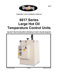
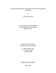
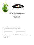
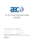
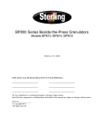
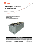
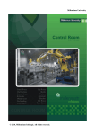
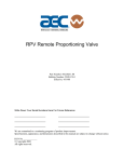
Operation and Installation Manual SCW Series Central Chilling Stations Important! Read Carefully Before Attempting to Install or Operate Equipment Part No. A0551795 Bulletin No. SC3-635.1 Write down your unit serial number(s) ________________ ________________ here for future reference ________________ ________________ ________________ ________________ ________________ ________________ Sterling is committed to a continuing program of product improvement. Specifications, appearance, and dimensions described in this manual are subject to change without notice. © Copyright Sterling 2008 All rights reserved. Part No. A0551795 Page 2 of 77 Effective 4/11/2008 Bulletin No. SC3-635.1 SCW Series Central Chilling Stations Safety Considerations Sterling SCW Series central chilling stations are designed to provide safe and reliable operation when installed and operated within design specifications, following national and local safety codes. To avoid possible personnel injury or equipment damage when installing, operating, or maintaining this equipment, use good judgment and follow these safe practices: ; Only PROPERLY TRAINED personnel familiar with the information within this manual should work on this equipment. ; Follow all local SAFETY CODES. ; Wear SAFETY GLASSES and WORK GLOVES. ; Disconnect and/or lock out power before servicing or maintaining the chiller. ; Use care when LOADING, UNLOADING, RIGGING, or MOVING this equipment. ; Operate this equipment within design specifications. ; OPEN, TAG, and LOCK ALL DISCONNECTS before working on equipment. Sterling recommends following OSHA Lock-Out/Tag-Out Standard 29 CFR 1910.147. ; Make sure the unit is properly GROUNDED before switching power on. ; When welding or brazing in or around this equipment, be sure VENTILATION is ADEQUATE. PROTECT adjacent materials from flame or sparks by shielding with sheet metal. An approved FIRE EXTINGUISHER should be close at hand and ready for use if needed. ; Do not jump or bypass any electrical safety control. ; Do not restore power until all tools, test equipment, chiller and related equipment have been removed. SCW Series Central Chilling Stations Page 3 of 77 Table of Contents 1 General Information ................................................. 8 ; 1-1 Introduction ....... 8 ; 1-2 Necessary Documents 8 ; 1-3 Models Covered 9 ; 1-4 Standard Features 9 ; 1-5 Available Options 10 2 Shipping Information ............................................. 16 ; 2-1 Unpacking and Inspection 16 ; 2-2 In the Event of Shipping Damages 16 ; 2-3 If the Shipment is Not Complete 17 ; 2-4 If the Shipment is Not Correct 17 ; 2-5 Returns.............. 17 ; 2-6 Uncrating Your New Chiller 18 3 Installation............................................................... 20 ; 3-1 Installation Location Considerations 20 ; 3-2 Making Electrical Connections 20 ; 3-3 Piping Considerations 22 ; 3-4 Making Process Water Connections 22 ; 3-5 Making Tank Piping Connections 23 ; 3-6 Water Connection Sizing Considerations 24 ; 3-7 Galvanic Corrosion Considerations 24 ; 3-8 Water Treatment Considerations 24 ; 3-9 Making Water-Cooled Condenser Connections 24 ; 3-10 Installing the Remote Air-Cooled Condenser 25 ; 3-11 Checking Motor Direction 26 4 Sequence Of Operation........................................ 277 ; 4-1 Staging .............. 28 ; 4-2 Alarms ............... 28 ; 4-3 Lead-Lag Compressors 28 ; 4-4 Lead-Lag Pumps 28 ; 4-5 Chilled Water Circuit 29 Page 4 of 77 SCW Series Central Chilling Stations ; 4-6 Refrigeration Circuit 29 ; 4-7 Freezestat Control 29 ; 4-8 High Pressure Cutout 31 ; 4-9 Low Pressure Cutout 31 ; 4-10 Flow Switch ....... 31 ; 4-11 Control Nipple ... 32 ; 4-12 32 Control Probe .... ; 4-13 Chilled Water Manifold ; 4-14 5 32 Optional Condenser Water Manifold 32 Startup Checklists .................................................. 34 ; 5-1 Introduction ....... 34 ; 5-2 Water-Cooled SCW Series Startup Checklist 34 ; 5-3 Water-Cooled SCW Series Startup 36 ; 5-4 Remote Air-Cooled SCW Series Startup Checklist 37 ; 5-5 Remote Air-Cooled SCW Series Startup 39 ; 5-6 Determining Flow Rate 40 ; 5-7 Shutdown .......... 40 6 ; 6-1 7 Graphic Panel Devices........................................... 41 Indicator Lights and Control Switches (MMI) 41 Using the Standard Touchscreen Interface ......... 43 ; 7-1 Operator Interface Introduction (MMI) 43 ; 7-2 Using the SCW Series Standard Operator Interface 44 ; 7-3 Getting Started on the SCW Series Standard Operator Interface 45 ; 7-4 Viewing and Operating Chiller Compressors 45 ; 7-5 Viewing and Operating Chiller Pumps 45 ; 7-6 Viewing Active Alarms and Handling Alarm Conditions 46 ; 7-7 Viewing and Setting System Temperatures 46 8 Using the Advanced Touchscreen Interface........ 48 ; 8-1 Touchscreen Interface Introduction (MMI) 48 ; 8-2 Using the SCW Series Advanced Touchscreen Interface 49 ; 8-3 Getting Started on the SCW Series Advanced Touchscreen Interface 50 ; 8-4 Viewing and Operating Chiller Compressors 50 SCW Series Central Chilling Stations Page 5 of 77 8-5 Viewing and Operating Chiller Pumps ................. 55 ; 8-6 Viewing Active Alarms and Handling Alarm Conditions 59 ; 8-7 Viewing and Setting System Temperatures 61 9 Routine Maintenance ............................................. 64 ; 9-1 Lubrication......... 64 ; 9-2 Condenser Maintenance 64 ; 9-3 Evaporator Maintenance 65 ; 9-4 Pump Motor Seal 65 9-5 Makeup Valve .......................................................... 65 ; 9-6 Recommended Pump Tank Spare Parts 65 ; 9-7 Preventive Maintenance Service 66 10 Troubleshooting ..................................................... 68 I Index ........................................................................ 72 Page 6 of 77 SCW Series Central Chilling Stations Charts and Figures 1 2 3 4 5 6 7 8 9 10 11 12 13 14 15 16 17 Typical Two-Circuit 60-195 Ton Water Cooled Chiller 11 Typical Two-Circuit 60-195 Ton Remote Air Cooled Chiller 13 Freezing Protection Curve 29 SCW Series Standard Control Panel 39 SCW Series Advanced Control Panel 40 SCW Series Standard Control Panel 44 SCW Series Advanced Control Panel 58 Main Menu Screen (Advanced Control Panel) 59 Chiller Status Screen (Advanced Control Panel) 61 Chiller Configuration Screen (Advanced Control Panel) 62 Compressor Run Time Display Screen (Advanced Control Panel) 64 Pump Status Screen 65 Pump Enables Screen 66 Pump Run Time Display Screen 68 Alarm Condition Screen 69 System Status Screen 71 Temperature Input Display Screen 72 SCW Series Central Chilling Stations Page 7 of 77 1 1-1 General Information Introduction Sterling SCW Series central water chilling stations are available in water-cooled and remote air-cooled designs. They differ only in the condensing media used. The SCW Series units are configured with two independent circuits using multiple compressors for each circuit. This manual lists information for these units. SCW Series chilling stations may be configured with stainless steel pump tanks for use as reservoirs for chilled water processes. These dual-well models hold hot and cold water before and after it is pumped through the chiller. Tanks have recirculation pump(s) to send return water to the chiller and process pump(s) to pump cooled water directly to process. Standby pumps may be utilized to distribute pump service or to allow uninterrupted chiller operation during pump maintenance. Properly installed, operated, and maintained SCW Series chilling stations provide many years of reliable operation. To get the most satisfaction from your new chiller, read and follow the instructions in this manual. 1-2 Necessary Documents The following documents are necessary for the operation, installation, and maintenance of Sterling SCW Series central chillers. Additional copies are available from Sterling. Familiarize the appropriate personnel with these documents: ; This manual. ; The schematic and connection diagram in the control enclosure. ; Operation and installation manuals for accessories and options selected by the customer. ; The Customer Parts List included in the information packet. Page 8 of 77 SCW Series Central Chilling Stations 1-3 Models Covered This manual provides operation, installation, and maintenance instructions for the SCW Series central chilling stations. Model numbers are listed on the serial tag. A model number followed by Q indicates a specially constructed unit, and not all information in this manual may apply. Make sure that you know the model number, serial number, and operating voltage of your chiller if you contact Sterling. 1-4 Standard Features • Two independent refrigeration circuits • High-efficiency screw compressors • Stainless steel brazed plate (60 & 75) Shell & Tube (90 – 195) evaporators • Cleanable shell and tube condensers (water-cooled models) • Electronic expansion valve • 2 remote single circuit condensers with variable speed lead fans and fan cycling (air-cooled models) • NEMA 12 electrical enclosure • Mitsubishi FX2N PLC control with F930GOT touchscreen interface. • High and low refrigerant pressure safeties • Touch-safe branch circuit fusing • Evaporator water piping manifold (Condenser manifold optional) • R-134a refrigerant • Digital low temperature freezestat • Liquid line solenoid and shut-off valves • Chilled water flow switches • 1 year warranty on parts and labor • 3 year warranty on controller SCW Series Central Chilling Stations Page 9 of 77 1-5 Available Options SCW Series central chillers are available with options to tailor the unit to your requirements. Some are factory installed; some can be retro-fitted in the field. Consult Sterling sales for more information. Available SCW Series options include: • Advanced control package including: Mitsubishi P2A PLC control with A970GOT – color touchscreen interface; provides control of up to nine additional chillers, cooling tower system, water treatment system • General Fault audible/visual alarm with elevated light stack • Non-fused rotary thru-the-door disconnect switches • Electrical operation available in 208, 460, and 575 volts, 60 Hz; 200, 380, and 415 volts, 50 Hz • UL/CUL-listed electrical subpanel • Water cooled condenser manifold • Onsite startup Standard Features on Remote Condensers Page 10 of 77 • Direct-drive 3-phase fan motors with ball bearings and internal overload protection • Electronic variable-speed control of lead fan and fan cycling for constant condenser head pressure control • Fans are 30” (76 cm) in diameter and have PVC-coated steel fan guards; 1½ hp (1.12 kW) variable-speed fans are 26” (66 cm) in diameter • Internal baffles between fan cells • UL listed in the United States and Canada • Patented floating tube coil to eliminate tube sheet leaks • Copper tube condenser coils have corrugated aluminum fins • Weather-proof control panel with factory-mounted door interrupt switch • High-efficiency condenser coil, designed for optimum performance • Aluminum housing provides corrosion protection for outdoor applications SCW Series Central Chilling Stations Model Number Nomeclature SCW W 060 SCW – Screw Compressor Central Chiller Condenser Type R – Remote Air Cooled W – Water Cooled (Nominal Unit Size) 060 075 090 100 115 145 165 195 SCW Series Central Chilling Stations Page 11 of 77 Figure 1 Typical Two-Circuit 60-195 Ton Water Cooled Chiller Model Cooling Capacity (tons) @ 50°F LWTc Capacity stages EER (BTUH/W) Evaporatord Nominal water flow (gpm) Condenserse Condenser connection (no manifold) Flange Conn. (in.) Evaporator manifold connection Victaulic Amp draw, nameplate Water-cooled (460/3/60 V)f Height Dimensions (in.) Width Depth Shipping weight (lbs) Max operating weight (lbs.) c d e f SCWW-xxx 75 90 74.9 88.8 Infinite Unloading 15.1 15.7 180 213 225 266 60 60.4 15.2 145 181 2.5 3 112 15.5 245 307 3 4 130 138 85 100 45 3,266 3,468 100 102.2 170 74 115 72 3,512 3,754 4,336 4,594 4,982 5,246 Based on 50ºF (10ºC) chilled water supply temperature and 85ºF (29ºC) tower water. Based on 2.4 gpm per ton (9.1 lpm per 3.517 kW). Based on availability of 85ºF (29ºC) tower water at 25 psi (172.4 kPa/1.7 bars) minimum. Multiply 460/3/60 amperage by 2.0 for 208-230/3/60 amperages; multiply by 1.2 for 380/3/60 amperages; multiply by 0.8 for 575/3/60 amperages Page 12 of 77 SCW Series Central Chilling Stations Model Cooling Capacity (tons) @ 50°F LWTc Capacity stages EER (BTUH/W) Evaporatord Nominal water flow (gpm) Condenserse Condenser connection (no manifold) Flange Conn. (in.) Evaporator manifold connection Victaulic Amp draw, nameplate Water-cooled (460/3/60 V)f Height Dimensions (in.) Width Depth Shipping weight (lbs) Max operating weight (lbs.) c d e f 115 116.3 15.5 279 349 3 4 216 77 124 72 5,298 5,584 SCWW-xxx 145 165 146.0 166.3 Infinite Unloading 16.2 15.9 350 399 438 499 4 6 195 193.1 16.2 463 579 250 282 316 8,844 9,428 81 137 75 9,376 10,102 9,580 10,364 Based on 50ºF (10ºC) chilled water supply temperature and 85ºF (29ºC) tower water. Based on 2.4 gpm per ton (9.1 lpm per 3.517 kW). Based on availability of 85ºF (29ºC) tower water at 25 psi (172.4 kPa/1.7 bars) minimum. Multiply 460/3/60 amperage by 2.0 for 208-230/3/60 amperages; multiply by 1.2 for 380/3/60 amperages; multiply by 0.8 for 575/3/60 amperages SCW Series Central Chilling Stations Page 13 of 77 Figure 2 Typical Two-Circuit 60-195 Ton Remote Air Cooled Chiller Model Cooling Capacity (tons) @ 50°F LWT Capacity stages EER (BTUH/W) Nominal water flow (gpm) Evaporator Evaporator manifold connection Victaulic No. of condenser fans per condenser Amp draw, nameplate Chiller (460/3/60 V) Condensers (per condenser) Dimensions (in.) of chiller Height Width Depth Dimensions (in.) of each Height condenser Width Depth Shipping weight (lbs) Chiller Condensers (each condenser) Max operating weight Chiller (lbs.) Condensers Model Cooling Capacity (tons) @ 50°F LWT Capacity stages EER (BTUH/W) Nominal water flow (gpm) Evaporator Evaporator manifold connection Victaulic No. of condenser fans per condenser Amp draw, nameplate Chiller (460/3/60 V) Condensers (per condenser) Dimensions (in.) of chiller Height Width Depth Dimensions (in.) of each Height condenser Width Depth Shipping weight (lbs) Chiller Condensers (each condenser) Max operating weight Chiller (lbs.) Condensers (each condenser) SCWR-xxx 75 90 67.1 79.1 Infinite Unloading 9.9 9.8 161 190 60 53.8 9.4 129 3 3 112 11 100 91.2 10 219 4 3 130 11 4 138 14 75 100 45 4 170 14 74 115 72 50 45.5 180 2,574 1,190 2,600 1,215 115 104.1 10.3 250 4 4 216 14 77 124 72 235 4,156 1,760 4,212 1,800 45.5 235 2,676 1,210 2,710 1,240 3,456 1,580 3,498 1,650 SCWR-xxx 145 165 130.5 148.4 Infinite Unloading 10.5 10.4 313 356 6 5 6 250 282 18 21 81 137 75 50 45.5 290 345 7,528 7,554 2,380 2,480 7,788 7,814 2,435 2,540 3,532 1,620 3,580 1,660 195 174.0 10.2 418 8 316 28 88 235 7,698 3,230 8,016 3,300 c Based on 50ºF (10ºC) chilled water supply temperature and 95ºF (35ºC) ambient air. d Based on 2.4 gpm per ton (9.1 lpm per 3.517 kW) e Multiply 460/3/60 amperage by 2.0 for 208-230/3/60 amperages; multiply by 1.2 for 380/3/60 amperages; multiply by 0.8 for 575/3/60 amperages Page 14 of 77 SCW Series Central Chilling Stations SCWR Series Remote Condenser Models Model Number SCWR60 SCWR75 SCWR90 SCWR100 SCWR115 SCWR145 SCWR165 SCWR195 Dia. in. 30 30 30 30 30 30 30 30 Motor hp c 1 ½ hp 3 ø 1 ½ hp 3 ø 1 ½ hp 3 ø 1 ½ hp 3 ø 1 ½ hp 3 ø 1 ½ hp 3 ø 1 ½ hp 3 ø 1 ½ hp 3 ø Fan(s) Refrigeration d Each Connections Charge Amps Air flow Discharge Liquid R-134a 460V Fans cfm e ODS(in.) ODS(in.) lbs. e 11.0 3 34,800 21/8 21/8 19 11.0 3 32,900 21/8 21/8 19 14.0 4 46,400 21/8 21/8 22 14.0 4 42,400 21/8 21/8 27 14.0 4 41,500 21/8 21/8 27 18.0 5 51,800 25/8 25/8 43 21.0 6 65,800 25/8 25/8 50 21.0 8 87,800 2 @ 21/8 2 @ 21/8 44 c ø represents electrical phase; all motors are 1,140 rpm. Multiply hp by 0.746 to convert to kW. d Refrigeration charge is for remote condenser only! e To convert cfm to cmh, multiply by 1.699. To convert lbs. to Kg, multiply by 0.454. SCW Series Central Chilling Stations Page 15 of 77 2 2-1 Shipping Information Unpacking and Inspection You should inspect your equipment for possible shipping damage. Thoroughly check the equipment for any damage that might have occurred in transit, such as broken or loose wiring and components, loose hardware and mounting screws, etc. 2-2 In the Event of Shipping Damages According to the contract terms and conditions of the Carrier, the responsibility of the Shipper ends at the time and place of shipment. Notify the transportation company’s local agent if you discover damage Hold the damaged goods and packing material for the examining agent’s inspection. Do not return any goods before the transportation company’s inspection and authorization. File a claim with the transportation company. Substantiate the claim by referring to the agent’s report. A certified copy of our invoice is available upon request. The original Bill of Lading is attached to our original invoice. If the shipment was prepaid, write us for a receipted transportation bill. Advise customer service regarding your wish for assistance and to obtain an RMA (return material authorization) number. Page 16 of 77 SCW Series Central Chilling Stations 2-3 If the Shipment is Not Complete Check the packing list as back-ordered items are noted on the packing list. In addition to the equipment itself, you should have: ; ................. Bill of lading ; ................. Packing list ; ................. Operating and Installation packet ; ................. Electrical schematic and panel layout drawings ; ................. Component instruction manuals (if applicable) Re-inspect the container and packing material to see if you missed any smaller items during unpacking. 2-4 If the Shipment is Not Correct If the shipment is not what you ordered, contact the parts and service department immediately at (262) 641-8610. Have the order number and item number available. Hold the items until you receive shipping instructions. 2-5 Returns Do not return any damaged or incorrect items until you receive shipping instructions from the shipping department. SCW Series Central Chilling Stations Page 17 of 77 2-6 Uncrating Your New Chiller ! WARNING ! DUE TO THE SIZE AND WEIGHT OF SCW SERIES CHILLERS, STERLING RECOMMENDS USING BONDED PROFESSIONAL MILLWRIGHTS TO UNLOAD AND MOVE SCW SERIES CHILLERS. Rig the chiller from the frame only, using spreader bars to prevent load transfer to any chiller components. Rig the frame from at least four points and balance the load before lifting to clear the skid. Use a forklift of adequate size when lifting the chiller by the fork pockets. Insert the forks all the way into the pockets and be sure to balance the load before lifting the chiller to clear the skid. Lift only as high as necessary. Use a pry bar to free the skid if necessary. Lower slowly. Retain the crating in case reshipment is necessary due to hidden shipping damage. Caution! Due to the weight of these units, use extreme caution when moving and placing SCW Series chillers. . Page 18 of 77 SCW Series Central Chilling Stations - Notes - SCW Series Central Chilling Stations Page 19 of 77 3 3-1 Installation Installation Location Considerations As with all equipment installations, follow all applicable codes and regulations. ; Locate close to the process to reduce piping expense. ; Locate adjacent to drain and city water sources. ; Consult a structural engineer to assure that the floor, mounting pad or structural steel support is of adequate strength. ; Allow for required service clearances necessary for condenser maintenance and easy access to all components. 3-2 Making Electrical Connections SCW Series systems are designed for three-phase voltage operation. Refer to the unit nameplate for proper voltage and amperage requirements. Make sure you provide a correctly sized and protected supply of electrical power to the unit. Important! Refer to National Electric Code (NEC) Article 430-24 through 430-26 for proper feeder conductor and supply disconnect sizing. Maintain a safe ground and disconnect the power supply before servicing the unit. A qualified electrician should make electrical connections, and disconnect and lock out electricity using OSHA 29 CFR 1910.147 standards when you need a service call. Check serial tag voltage and amperage requirements and make sure your electrical service conforms before making any electrical connections. Total running amps for the SCW Series systems are listed on the nameplate. Customer connections can be run to the supply terminals from either side of the unit. Make sure that all three phases are wired correctly. If not wired properly, the unit will run backwards. Again, check the unit nameplate for correct voltage and amperage. Page 20 of 77 SCW Series Central Chilling Stations ! DANGER Improper electrical connections will damage the unit and cause serious operator injury or death! Compressor damage will occur if compressors are run backwards. Bring properly sized power leads and ground from a fused disconnect (installed by your electrician) to the unit. Provide external overcurrent protection to the unit, using circuit breakers or fuses. If you use fuses, make sure that they are dual-element timedelay fuses, sized according to your electrical code. Make sure that all electrical connections are tight. Important! 1. Electrical connections must comply with all applicable electrical codes. 2. The chiller must be grounded in accordance with NEC Article 250. 3. Voltage must be within plus or minus ten percent (±10%) of the nameplate rating. 4. Make sure your installer provides external protection. Check Compressor Rotation Before Starting Unit! 1. Connect a phase monitor and phase incoming power ABC. 2. Connect a refrigerant gauge to the suction service valve. Fully front seat the service valve and open one full turn. 3. Bump start the compressor by switching off then on quickly 0.5 to 1 second. If the rotation is correct, the suction pressure will drop immediately. A rise in pressure will indicate the wrong rotation. If this occurs, change over two electrical phases of the incoming power supply (do not change phase at the compressor starter). Check the electrical wiring schematic provided in your Customer Information packet for additional information. SCW Series Central Chilling Stations Page 21 of 77 Note: • Never switch contactor leads or motor leads for reversing rotation. • Do not use contactor or motor leads for phase matching. • Compressor damage will occur if the compressor is run in reverse. The compressor motor protector checks for correct phasing and will not allow it to start in reverse. • If you discover that compressor rotation is reversed, correct it by switching any two main power leads into the disconnect switch or distribution block on the unit. Check your work and proceed to the following Piping Considerations section. 3-3 Piping Considerations Piping systems vary with process application and pump tank configuration. Typical system configuration drawings are provided in this manual; the details may or may not apply to your application. Piping systems must be designed by a person knowledgeable in piping system design and configuration. Sterling’s Contracting Department can design and install a piping system tailored to your process. 3-4 • All water piping returning to the pump tank must be equipped with an inverted trap with a vacuum breaker at the high point of the system to prevent mains from siphoning into the pump tank. • Run mains full size in order to reduce pressure drop in the system and provide maximum pressures at the ends of the mains. Making Process Water Connections All Models All SCW Series chilling stations have two chilled water connections per unit, and on water-cooled models, one more set of water connections for condenser water: To Process The chilled water supply outlet leading to the process being controlled. Page 22 of 77 SCW Series Central Chilling Stations From Process The chilled water return for water returning back to the chiller from the process to be cooled and recirculated. Adjust the butterfly valve for the pressure drop that corresponds to the model number of the chiller. Pressure drop is equal to supply pressure minus return pressure Model Number SCWW/R60 SCWW/R75 SCWW/R90 SCWW/R100 SCWWR115 SCWW/R145 SCWW/R165 SCWW/R195 3-5 Water Side Pressure Drop Condenser (each) Evaporator (each) Flow (gpm) PD (psi) Flow (gpm) PD (psi) 91 4.0 72 5.3 102 4.7 90 4.5 117 4.4 107 5.6 150 5.5 123 3.9 166 4.3 140 3.0 196 4.1 175 4.8 219 4.1 200 4.6 278 4.7 232 6.0 Making Tank Piping Connections If you have purchased the SCW Series central chilling station with the integral pump tank, please proceed with this section. Return Bring the chilled water returning from the process to the pump tank warm From Process side. This line is sized according to the flow rate from the process to the pump tank. See Section 3-3 on Page 21 for more information on piping considerations. Important! Do not use the SCW Series unit to support piping. Makeup Connect a city water source to maintain water level in the pump tank. Overflow Connect the OVERFLOW outlet to an approved, trapped drain to permit excess water in the pump tank to overflow to the drain. The overflow line is sized according to the size of the pump tank. To Drain Connect to a 1½” line (approx. 63 mm) leading to an approved, trapped drain. You can drain the pump tank if necessary. SCW Series Central Chilling Stations Page 23 of 77 3-6 Water Connection Sizing Considerations Important! • Run all external chilled water connections with adequate size to the process. • Provide the largest possible openings and passages for the flow of chilled water through platens, dies, molds, or other pieces of equipment. • Minimum external pressure drop is critical for proper operation. 3-7 Galvanic Corrosion Considerations Water circuit piping components are primarily ferrous (iron) and react electro-chemically with non-ferrous metallic materials such as copper. Some water has dissolved minerals that will greatly accelerate the reaction between dissimilar metals. Use PVC or ferrous piping to minimize galvanic action. If piping must be copper, use dielectric unions at the chiller. 3-8 Water Treatment Considerations Water treatment is important in any piping system. In some locations, raw water may be used in the system without problem; in other locations, it will result in large deposits of scale and corrosion. Sterling offers a complete line of water treatment equipment. Contact your Sterling sales representative for water testing and treatment options. 3-9 Making Water-Cooled Condenser Connections SCW Series water-cooled chilling stations use city or tower water as a cooling medium. All external condenser supply and discharge piping and connections should be of adequate size. Water regulating valves are not required on the SCW Central Chiller if the tower water does not fall below 65°F (18ºC). Water flow must be adjusted based upon the pressure drop in the following table on the next page. Page 24 of 77 SCW Series Central Chilling Stations Two connections are made to each SCW Series unit: Condenser Water In The city or tower water supply inlet is located at the side or rear of the chiller. • Water pressure ≥ 25 psi (≥ 172.4 kPa/≥ 1.72 bars) • Water temperature ≤ 85°F (≤ 29ºC) Condenser Water Out The return outlet, located at the chiller side or rear is connected to a cooling tower inlet, a sewer or other approved discharge receiver. • A water regulating valve is an optional feature in the condenser water out line. • Adjust the butterfly valve for the pressure drop that corresponds to the model number of the chiller. Pressure drop is equal to supply pressure minus return pressure. (If a water regulating valve has been supplied, adjustment is not required.) Model Number SCWW/R60 SCWW/R75 SCWW/R90 SCWW/R100 SCWWR115 SCWW/R145 SCWW/R165 SCWW/R195 Water Side Pressure Drop Condenser (each) Evaporator (each) Flow (gpm) PD (psi) Flow (gpm) PD (psi) 91 4.0 72 5.3 102 4.7 90 4.5 117 4.4 107 5.6 150 5.5 123 3.9 166 4.3 140 3.0 196 4.1 175 4.8 219 4.1 200 4.6 278 4.7 232 6.0 3-10 Installing the Remote Air-Cooled Condenser SCW Series models use the surrounding air to cool the remote condenser. All models have variable speed fans and low ambient controls to allow proper operation down to -20°F (-29ºC) outdoor air temperature. Install the remote air cooled condenser where there is: • Greater than or equal to -20°F (-29ºC) air temperature. • Free passage of air for condensing. • Adequate structural support. • Protection from strong winds and drifting snow. • Provisions for removal of heated air from the area. SCW Series Central Chilling Stations Page 25 of 77 • No steam, hot air or fume exhausts drawn into the condenser coils. • Service accessibility. SCW Series condensing pressure with 95ºF (35ºC) condenser air R-134a = 171 psi (1,179 kPa/11.79 bars) Note: Due to the variables involved in remote air-cooled condenser installations, no set or standard piping procedure exists. Each installation must be designed and installed by qualified persons. Follow the instructions supplied with the condenser. 3-11 Checking Motor Direction Compressor Check Compressor Rotation Before Starting Unit! 1. Connect a phase monitor and phase incoming power ABC. 2. Connect a refrigerant gauge to the suction service valve. Fully front seat the service valve and open one full turn. 3. Bump start the compressor by switching off then on quickly 0.5 to 1 second. If the rotation is correct, the suction pressure will drop immediately. A rise in pressure will indicate the wrong rotation. If this occurs, change over two electrical phases of the incoming power supply (do not change phase at the compressor starter). Note: • Never switch contactor leads or motor leads for reversing rotation. • Do not use contactor or motor leads for phase matching. • Compressor damage will occur if the compressor is run in reverse. The compressor motor protector checks for correct phasing and will not allow it to start in reverse. • If you discover that compressor rotation is reversed, correct it by switching any two main power leads into the disconnect switch or distribution block on the unit. Water Pump A positive pressure of 20 to 30 psi (137.9 to 206.8 kPa/1.38 to 2.07 bars) on the TO PROCESS line indicates correct pump rotation. Page 26 of 77 SCW Series Central Chilling Stations Condenser Fan On SCW Series remote air-cooled units, air should be drawn through the condenser and discharge up from the condenser. Changing fan rotation direction • Disconnect and lock out power at the fused disconnect. • If all fans are going backwards, reverse any two main power leads. • If only some of the fans are going backwards, switch any two of their respective motor leads. -Notes- SCW Series Central Chilling Stations Page 27 of 77 4 4-1 Sequence Of Operation Staging 1. The system uses a PID control algorithm to regulate the chilled water temperature. As the required control effort increases or decreases, the system compressors are infinitely unloaded or turned on/off to keep the temperature at the specified set-point. 2. Compressor anti-recycle time is two (2) minutes. 4-2 Alarms If a fault occurs, that compressor or circuit is deactivated. The load will automatically shift to any other compressors that are currently ON-LINE, but not running. Lead/Lag rotation will continue to function. Compressors that are faulted will be removed from the rotation order. 4-3 Lead-Lag Compressors The system automatically rotates the compressor order to generate a Lead/Lag rotation. Any time a compressor is faulted or manually taken OFF-LINE, it will be removed from the Lead/Lag rotation. Once the fault is cleared or manually put ON-LINE, the compressor is returned to the Lead/Lag rotation at the end of the rotation order. 4-4 Lead-Lag Pumps The system automatically rotates the pump order to generate a Lead/Lag rotation. Any time a pump is faulted or manually taken OFF-LINE, it will be removed from the Lead/Lag rotation. Once the fault is cleared or manually put ON-LINE, the pump is returned to the Lead/Lag rotation at the end of the rotation order. Page 28 of 77 SCW Series Central Chilling Stations 4-5 Chilled Water Circuit If your central chilling station is equipped with the optional integral pump tank, make the process cooling water supply connection at the P1 manifold at the left side of the pump tank at the exposed connection. Bring the process cooling water return connection to the Hot well of the tank on the right side at the flanged connection. Warm coolant (water and ethylene glycol mixture) returns from the process to the tank, then gets pumped through the evaporator where it is cooled. The coolant flows to the process and returns to repeat the cycle. 4-6 4-7 Refrigeration Circuit • SCW Series chilling station air- and water-cooled unit refrigeration cycles differ only in the way the compressed gas is condensed to a liquid. • Liquid refrigerant from the condenser passes through a shut-off valve into a filter/dryer. • The refrigerant then passes through the sight glass and solenoid valves into the thermal expansion valve which regulates flow; the valve lowers pressure and boiling point. Heat from the fluid causes the refrigerant to boil off into a vapor. • The refrigerant vapor flows through the suction line back into the compressor. • The refrigerant gives up heat as it re-condenses to a liquid in the condenser. Freezestat Control The freezestat shuts down the compressor if the chilled water temperature approaches the freezing point. The chilled water pump on the system will continue to run. It is factory-set at 40°F (4ºC) or 10°F (6ºC) below the rated capacity operating temperature of 50°F (10ºC). SCW Series Central Chilling Stations Page 29 of 77 If you want lower chilled water temperatures, you’ll need to mix process water with industrial- (not automotive) grade ethylene or propylene glycol with rust inhibitor to provide protection down to 20°F (12ºC) below the operating temperature you want. Figure 3 below shows the proper mixtures needed to provide protection to 20°F (12ºC) below the operating temperature you want. You can then reset the freezestat cutout temperature to a temperature of 10°F (6ºC) below the operating temperature you selected. Caution! Make sure all freezestat adjustments are performed by a qualified refrigeration service technician. The Sterling product warranty does not cover system freeze-up! Figure 3 Freezing Protection Curve 60 Ethylene glycol required for evaporator freeze protection 50 Ethylene glycol percent by volume 40 30 20 10 0 -50ºF -40ºF -30ºF -20ºF -10ºF 0ºF 10ºF 20ºF 30ºF 40ºF 50ºF 60ºF -46ºC -40ºC -34ºC -29ºC -23ºC -18ºC -12ºC -7ºC -1ºC 4ºC 10ºC 16ºC Chilled water operating temperature ºF / ºC Page 30 of 77 SCW Series Central Chilling Stations 4-8 High Pressure Cutout This electro-mechanical safety feature opens the control circuit if the system condensing pressure exceeds a safe level. High pressure cutout setting Model SCW Series water-cooled and remote air-cooled chilling stations psi kPa bars 290 psi 2,000 kPa 20 bars Important! The high pressure cutout is a manual reset control, so you should reset it once. If the problem persists, call a refrigeration service technician to analyze the problem and to reset the control. 4-9 Low Pressure Cutout This encapsulated switch safety feature prevents the compressor suction pressure from dropping below a pre-set point. It is factory set to open the control circuit when pressure drops below a safe level. The chiller will restart when the suction pressure reaches 30 psi (206.9 kPa/2.1 bars). Opens control circuit @ psi kPa bars Model SCW Series water-cooled and remote air-cooled chilling stations 15 psi 103.4 kPa Resets control circuit @ psi kPa bars 1.0 bars 30 psi 206.9 kPa 2.1 bars 4-10 Flow Switch The flow switch shuts down the chiller if the evaporator water flow falls below a safe operating gallons-per-minute (liters-per-minute) flow rate. SCW Series Central Chilling Stations Page 31 of 77 4-11 Control Nozzle All SCW Series chilling station evaporators have two control nozzles. The flow switch, freezestat, and flush port are located in the control nozzle. Pressure gages are mounted in the control nozzles to aid in achieving proper flow through the evaporator and balancing flows. Pressure drop between evaporator entering water pressure and evaporator leaving water pressure can be converted to gallons per minute using the pressure drop charts below. Model Number SCWW/R60 SCWW/R75 SCWW/R90 SCWW/R100 SCWWR115 SCWW/R145 SCWW/R165 SCWW/R195 Water Side Pressure Drop Condenser (each) Evaporator (each) Flow (gpm) PD (psi) Flow (gpm) PD (psi) 91 4.0 72 5.3 102 4.7 90 4.5 117 4.4 107 5.6 150 5.5 123 3.9 166 4.3 140 3.0 196 4.1 175 4.8 219 4.1 200 4.6 278 4.7 232 6.0 4-12 Control Probe Two control probes sense temperatures. One probe measures the temperature of the hot well and the other does the same for the cold well of the reservoir. These temperatures are used by the PLC controller to sequence the compressors, based on load. 4-13 Chilled Water Manifold The chilled water manifold allows one-point connections of TO PROCESS piping. The Sch. 40 steel piping includes butterfly valves at each evaporator for flow balancing and circuit isolation; optional pressure gauges can be installed. 4-14 Optional Condenser Water Manifold The optional condenser water manifold allows one-point connection of TO TOWER (drain) and FROM TOWER (city water) piping. Sch. 40 steel include butterfly valves for each condenser. Page 32 of 77 SCW Series Central Chilling Stations - Notes - SCW Series Central Chilling Stations Page 33 of 77 5 5-1 Startup Checklists Introduction Important! These lists assume the installation information in this manual has been read and followed. Have new chillers started up and checked by a qualified refrigeration service technician. Sterling offers factory startup for SCW Series chilling stations. Call the Sterling Service Department at 1 (800) 233-4819 for more details. 5-2 Water-Cooled SCW Series Startup Checklist ; Check the shipping papers against the serial tag to be sure chiller size, type and voltage is correct for the process. ; Check the transformer primary voltage connections to be sure they are configured for the electrical power you are using. ; The voltage at the main power connection must be within plus or minus ten percent (±10%) of the voltage listed on the serial tag. ; Phase imbalance must be less than two percent (<2%). ; Electrical connections must conform to all applicable codes. ; Complete the chilled water TO PROCESS and FROM PROCESS connections. ; The optional or field installed chilled water supply and return valves on the chiller must be open. ; Be sure the pump tank and chilled water circuit are filled with a water/glycol mixture that provides freeze protection to 20°F (12ºC) below the leaving water temperature you want. ; Complete the tower or city condenser WATER IN and WATER OUT connections. Provide an adequate condenser water supply; 2 gpm per ton for city water or 3 gpm per ton for tower water operation. ; Remove all tools, foreign matter and debris from the pump tank reservoir and piping. Page 34 of 77 SCW Series Central Chilling Stations ; Complete all piping leading to and from the pump tank. Observe all applicable codes. ; Complete all electrical wiring. Observe all applicable codes. ; Prepare all related equipment in the system for operation. ; Check for proper compressor rotation direction. To confirm proper rotation: 1. Connect a phase meter and phase incoming power ABC. 2. Connect a refrigerant gauge to the suction service valve. Fully front seat the service valve and open one full turn. 3. Bump start the compressor by switching off then on quickly 0.5 to 1 second. If the rotation is correct, the suction pressure will drop immediately. A rise in pressure will indicate the wrong rotation. If this occurs, change over two electrical phases of the incoming power supply (do not change phase at the compressor starter). Note: • Never switch contactor leads or motor leads for reversing rotation. • Do not use contactor or motor leads for phase matching. • Compressor damage will occur if the compressor is run in reverse. The compressor motor protector checks for correct phasing and will not allow it to start in reverse. • If you discover that compressor rotation is reversed, correct it by switching any two main power leads into the disconnect switch or distribution block on the unit. ; Open the 1” (approx. 25 mm) makeup water valve and allow the tank to fill until the automatic float valve shuts off. The float level should be adjusted so the standing water level is 8” (20 cm) from the top of the tank. ; Close the discharge butterfly valve, crack it open, then start the pump and observe the gauge. ; Check for proper pump rotation direction. To confirm proper rotation: 1. Observe a pump pressure gauge connected to the suction and discharge sides of the pump casing through two ¼” (approx. 6.4 mm) gauge cocks. SCW Series Central Chilling Stations Page 35 of 77 2. Close the gauge cock leading to the pump suction and open the gauge cock leading to the pump discharge. 3. Close the discharge butterfly valve, crack it open, then start the pump and observe the gauge. • If the gauge indicates within 15 psi (103.4 kPa/1.03 bars) below the pump curve, pump rotation is correct. Pump rotation is clockwise opposite the shaft end. • If the gauge indicates 20 psi (137.9 kPa/1.38 bars) or more below the pump curve, the pump is running backwards. Reverse rotation by interchanging any two power mains to the pump motor or starter. • Recheck the pressure to be sure it increased. ; Check the water level in the pump tank to be sure the pump does not run dry while the system piping is being filled. ; Check your work and proceed to the Startup procedure. 5-3 Water-Cooled SCW Series Startup 1. Start the chiller by pushing the Start button on the control panel of the unit. 2. The screen will display the Main Menu screen. 3. If your chiller has been setup to control the pump tank, the recirculation pump will turn on first, then after 5 seconds the process pump will turn on. If configured with a standby pump, the lead/lag will control which pump turns on. 4. Fifteen (15) seconds after the last pump turns on the first compressor will turn on. Based on the temperature of the water, the controller will turn on compressors every 15 seconds. 5. Adjust the Freezestat cut-out, located in the main electrical enclosure, to 10°F (6ºC) below the process temperature set point you want. Note: If the recirculation pump does not turn on (or that the flow switch is not satisfied) the compressors will not be allowed to turn on. 6. Check the pump(s) amp draws and pressures. The amp draws must be within the pump(s) running load and service factor amps. Page 36 of 77 SCW Series Central Chilling Stations 7. Operate the chiller, looking for leaks and listening for unusual noises or vibrations that could indicate improper operation. 5-4 Remote Air-Cooled SCW Series Startup Checklist ; Check the shipping papers against the serial tag to be sure chiller size, type and voltage is correct for the process. ; Check the transformer primary voltage connections to be sure they are configured for the electrical power you are using. ; The voltage at the main power connection must read within plus or minus ten percent (±10%) of the voltage listed on the serial tag. ; Phase imbalance must be less than two percent (<2%). ; Electrical connections must conform to all applicable codes. ; Complete the chilled water TO PROCESS and FROM PROCESS connections. ; The optional or field installed chilled water supply and return valves must be open. ; Be sure the tank and chilled water circuit piping are filled with a water/glycol mixture. The water/glycol mix should provide freeze protection to 20°F below the leaving water temperature you’ve selected. ; The air cooled condenser should have an adequate supply of air for proper operation. ; Connect the main power to the unit and bump-start it to check for proper rotation direction. If the fans are operating backwards, reverse any two main power leads at the incoming terminal block. ; Remove all tools, foreign matter and debris from the pump tank reservoir and piping. ; Complete all piping leading to and from the pump tank. Observe all applicable codes. ; Complete all electrical wiring. Observe all applicable codes. ; Prepare all related equipment in the system for operation. ; Check for proper compressor rotation direction. To confirm proper rotation: 1. Connect a phase meter and phase incoming power ABC. SCW Series Central Chilling Stations Page 37 of 77 2. Connect a refrigerant gauge to the suction service valve. Fully front seat the service valve and open one full turn. 3. Bump start the compressor by switching off then on quickly 0.5 to 1 second. If the rotation is correct, the suction pressure will drop immediately. A rise in pressure will indicate the wrong rotation. If this occurs, change over two electrical phases of the incoming power supply (do not change phase at the compressor starter). Note: • Never switch contactor leads or motor leads for reversing rotation. • Do not use contactor or motor leads for phase matching. • Compressor damage will occur if the compressor is run in reverse. The compressor motor protector checks for correct phasing and will not allow it to start in reverse. • If you discover that compressor rotation is reversed, correct it by switching any two main power leads into the disconnect switch or distribution block on the unit. ; Open the 1” (approx. 25 mm) makeup water valve and allow the tank to fill until the automatic float valve shuts off. The float level should be adjusted so the standing water level is 8” (20 cm) from the top of the tank. ; Check for proper pump rotation direction. To confirm proper rotation: Page 38 of 77 1. Observe a pump pressure gauge connected to the suction and discharge sides of the pump casing through two ¼” (approx. 6.4 mm) gauge cocks. 2. Close the gauge cock leading to the pump suction and open the gauge cock leading to the pump discharge. 3. Close the discharge butterfly valve, crack it open, then start the pump and observe the gauge. • If the gauge indicates within 15 psi (103.4 kPa/1.03 bars) below the pump curve, pump rotation is correct. Pump rotation is clockwise opposite the shaft end. • If the gauge indicates 20 psi (137.9 kPa/1.38 bars) or more below the pump curve, the pump is running backwards. Reverse rotation by interchanging any two power mains to the pump motor or starter. • Recheck the pressure to be sure it increased. SCW Series Central Chilling Stations ; Check the water level in the pump tank to be sure the pump does not run dry while the system piping is being filled. ; Check your work and proceed to the Startup procedure in the following section. 5-5 Remote Air-Cooled SCW Series Startup 1. Start the chiller by pushing the Start button on the control panel of the unit. 2. The touchscreen will display the Main Menu screen. 3. If your chiller has been setup to control the pump tank, the recirculation pump will turn on first, then after 5 seconds the process pump will turn on. If configured with a standby pump, the lead/lag will control which pump turns on. 4. Fifteen (15) seconds after the last pump turns on, the first compressor will turn on. Based on the temperature of the water, the controller will turn on compressors every 15 seconds. 5. Adjust the Freezestat cut-out, located in the main electrical enclosure, to 10°F (6ºC) below the process temperature set point you want. Note: If the recirculation pump does not turn on (or that the flow switch is not satisfied) the compressors will not be allowed to turn on. 6. Check the pump(s) amp draws and pressures. The amp draws must be within the pump(s) running load and service factor amps. 7. Operate the chiller, looking for leaks and listening for unusual noises or vibrations that could indicate improper operation. 8. Check condenser fans for pressure switch settings as shown in the table below: Fan number 1 2 3 4 5 psi 155 170 185 200 Set on Set off kPa bars psi kPa bars Not applicable; Fan 1 is a variable-speed fan 1,069 10.7 120 828 8.3 1,172 11.7 135 931 9.3 1,276 12.8 150 1035 10.3 1,379 13.8 165 1,138 11.4 SCW Series Central Chilling Stations Page 39 of 77 5-6 Determining Flow Rate To determine flow: 1. Close the gauge cock leading to the pump suction side and open the gauge cock leading to the pump discharge. 2. Start the pump and make note of the discharge pressure in psi (kPa/bars). 3. Check the pump curve for the appropriate horsepower pump at the discharge pressure psi. 4. Project this point down to find the flow in gpm (lpm). 5. Process pumps can be left wide open if running amps are below full load amps. 5-7 Shutdown 1. Ready process and related equipment for shut down. 2. Donot turn off main power until chiller completes the shutdown sequence (approximately 2 minutes). 3. Close the water make up valve. 4. If the system is to be drained, open the 2” drain valve. Figure 4 SCW Series Standard Control Panel Figure 5 SCW Series Advanced Control Panel -Notes- Page 40 of 77 SCW Series Central Chilling Stations 6 6-1 Graphic Panel Devices Indicator Lights and Control Switches (MMI) System On The green System On indicator lights when the main power switch is on and the control circuit is energized. Start The Start push-button lets you energize the unit. Stop The Stop push-button lets you de-energize the unit. Touchscreen Interface The color touchscreen interface gives you control over the chilling station. It has an easy-to-use control menu that lets you quickly change or adjust chiller settings and also gives you all the operation information you need to control the unit effectively. See Chapter 7 on Page 43 for more information on the Standard touchscreen interface operation. See Chapter 8 on Page 57 for more information on the Advanced touchscreen interface operation. SCW Series Central Chilling Stations Page 41 of 77 -Notes- Page 42 of 77 SCW Series Central Chilling Stations Using the Standard Operator Interface 7 7-1 Operator Interface Introduction The Standard touchscreen interface lets you control your SCW Series central chilling station. You can do such things as: • Control compressors and optional pumps • View current statuses of operation, such as pressures, temperatures, and capacities • Handle alarm conditions The sections in this chapter list special instructions for the standard operator interface. Note: The screens shown in this chapter are sample screens. Actual screen representations may be slightly different in appearance, but are no different in operation. On all screens in this controller, the F4 button is reserved for the previous screen function. Some screens, such as the chiller status screen, do not have sufficient space to display a prompt that the F4 performs this function. However, the F4 button will always move to the previous screen and will eventually return to the Main Menu. SCW Series Central Chilling Stations Page 43 of 77 Figure 6 SCW Series Standard Control Panel 7-2 Using the SCW Series Standard Operator Interface Page 44 of 77 SCW Series Central Chilling Stations 7-3 Getting Started on the SCW Series Standard Operator Interface 7-4 Viewing and Operating Chiller Compressors Viewing Compressor Status Operating the chiller compressors Setting Compressor Lead/Lag Times and Activating Compressor Lead/Lag Operation Viewing Compressor Run Times 7-5 Viewing and Operating Chiller Pumps Viewing Chiller Pump Status Operating Chiller Pumps Setting Pump Lead/Lag Times and Activating Pump Lead/Lag Operation Viewing Pump Run Times SCW Series Central Chilling Stations Page 45 of 77 7-6 Viewing Active Alarms and Handling Alarm Conditions ! CAUTION Never attempt to service a unit until a qualified electrician has opened and locked out the main disconnect using OSHA 1910.147 standards. All electrical connections must be done by a qualified electrician. ! WARNING Disconnect all power to the unit, let the unit cool down, and turn off the water prior to any servicing. Failure to do so can result in SERIOUS INJURY OR DEATH! 7-7 Viewing and Setting System Temperatures Page 46 of 77 SCW Series Central Chilling Stations Setting System Temperatures SCW Series Central Chilling Stations Page 47 of 77 Using the Advanced Touchscreen Interface 8 8-1 Touchscreen Interface Introduction (MMI) The Advanced touchscreen interfaces let you control your SCW Series central chilling station. You can do such things as: • Control compressors and optional pumps • View current statuses of operation, such as pressures, temperatures, and capacities • Handle alarm conditions The sections in this chapter list special instructions for operating either touchscreen interfaces. Note: The screens shown in this chapter are sample screens. Actual screen representations may be slightly different in appearance, but are no different in operation. Also, the PLC is configured based on options and system configuration at the time of order. These screens are the basic ones to startup the chiller. Page 48 of 77 SCW Series Central Chilling Stations Figure 7 SCW Series Advanced Control Panel 8-2 Using the SCW Series Advanced Touchscreen Interface SCW Series Central Chilling Stations Page 49 of 77 8-3 Getting Started on the SCW Series Advanced Touchscreen Interface Figure 8 Main Menu Screen The Main Menu screen lets you gain access to: • “Active Alarms” contains the current alarm(s) of the system • “Al;arm History” contains the last thirty (30) alarms that were activated. • “Compressor Hourmeters” contains the lifetime and resettable hour meters to show the number of hours that the compressors have been running • If the chiller was configured to operate the chilled water pump tank, there are three screens to configure and view the pump tank setup. The configuration screen allows for the user to turn on or off any of the pumps as well as configuring the lead/lag rotation (if multiple pumps were configured) • “Chiller Configuration” shows the configuration of the chiller itself including the chiller temperature setpoint, temperature alarm settings, as well as setting up the lead/lag rotation, and the ability to turn on and off the compressors. • “PanelView Utilities” and “ACS Service” are both password protected sections of the PLC that are used to configure the display and the initial configuration of the chiller and system. The following sections in this chapter list the information you need to navigate through these screens for operating and monitoring your SCW Series central chilling station with the Standard Control Package. 8-4 Viewing and Operating Chiller Compressors Viewing Compressor Status To view the status of the chiller compressors, start at the Main Menu screen, then: Page 50 of 77 SCW Series Central Chilling Stations Press the Up or Down buttons on the right side of the screen to highlight “System Information” Press ↵ The chiller status screen displays: Figure 9 Chiller Status Screen The Chiller Status screen shows the status for compressors within the system. Only compressors that are included in the system will SCW Series Central Chilling Stations Page 51 of 77 be shown on this screen. Compressors will display one of the following states: 1. OFFLINE – This indicates that the compressor has been turned off in the compressor enable/disable screen. The compressor will not be called to operate until it has been re-enabled. The color code for this indication is black. 2. READY – Indicates that the compressor is enabled and ready to run. However, the current loading does not require the compressor to be running. This compressor will be automatically started when needed. The color code for this indication is yellow. 3. RUNNING – Compressor is currently running. The color code for this indication is green. 4. FAULT – A safety on the compressor indicates a fault condition and the compressor has been deactivated. Once the problem is remedied, the compressor will return to a READY state unless it is put in the OFFLINE state. The color code for this indication is red. Operating the chiller compressors To enable or disable the individual compressors, start at the Main Menu, then: Press the Up or Down buttons on the right side of the screen to highlight “Chiller Configuration” Press the ↵ button The configuration menu screen displays: Figure 10 Chiller Configuration Screen Page 52 of 77 SCW Series Central Chilling Stations Touch the screen corresponding with the compressor you want to bring On-Line or Off-Line. The background color of the square turns green for On-Line and black for Off-line. Setting Compressor Lead/Lag Times and Activating Compressor Lead/Lag Operation While in the Configuration Menu, the compressors can be setup in a lead/lag configuration using interval hours. By pressing the “Compressor Rotation Interval” button, a numeric keypad will be displayed and allow the user to change the timeframe of the interval. To activate the Lead/Lag operation, touch the “Compressor Rotation” button. The status of the button will change to Enabled (green background), or Disabled (black background). SCW Series Central Chilling Stations Page 53 of 77 Viewing Compressor Run Times From the Main Menu, use the Up or Down buttons to highlight the “Compressor Hourmeters” menu. Scroll to select the compressors. Then press ↵ to display the hourmeters. Note: This is a complete list of all compressors that may be included in the system. Any compressor that is not included in the system will not accumulate time. The Compressor Run Time screen displays: Figure 11 Compressor Run Time Display Screen Page 54 of 77 SCW Series Central Chilling Stations Two hourmeters are kept for each compressor in the system. The first is a lifetime meter. This measures the total time that the compressor has been operational in the lifetime of the chiller. The second is a resettable hourmeter. This hourmeter can be cleared to monitor run time on specific intervals. In order to clear the resettable hourmeter, press the Hour Meter Reset button (as prompted on the screen) 8-5 Viewing and Operating Chiller Pumps If your chiller system was configured to operate the pump(s) of the chilled water pump tank, the user may view the status of the process and recirculation pumps. Viewing Chiller Pump Status To view the status of the pumps, start from the Main Menu, then: SCW Series Central Chilling Stations Page 55 of 77 Press the Up or Down buttons to highlight either “System Information”. Press ↵ The Pump Status Screen appears Figure 12 Pump Status Screen Only pumps that are included in the system will be shown on this screen. Pumps will display one of the following states: 1. OFFLINE – This indicates that the pump has been turned off in the pump enable/disable screen. The pump will not be called to operate until it has been re-enabled. The color code for this indication is black. 2. READY – Indicates that the pump is enabled and ready to run. However, the current number of pumps specified to run does not require this pump to operate. The color code for this indication is yellow. Page 56 of 77 SCW Series Central Chilling Stations 3. RUNNING – Pump is currently running. The color code for this indication is green. 4. FAULT – A safety on the pump indicates a fault condition and the pump has been deactivated. Once the problem is remedied, the pump will return to a READY state unless it is put in the OFFLINE state. The color code for this indication is red. Operating Chiller Pumps To turn on and off the pumps, start from the Main Menu, then: Press the Up or Down buttons to highlight either “Chilled Water Pump Tank Configuration”. Press ↵ The Pump Enables Screen appears Figure 13 Pump Enables Screen Any pump that is disabled to the OFF-LINE position will not be called to operate. Simply press the button of the desired pump to SCW Series Central Chilling Stations Page 57 of 77 toggle the state of the pump from the ON-LINE to OFF-LINE state. Setting Pump Lead/Lag Times and Activating Pump Lead/Lag Operation While in the Configuration Menu, the pump lead/lag (rotation) can be enabled or disabled. Simply press the Process or Recirculation Pump Interval button on the screen to toggle between Enabled and Disabled. The interval between rotating pumps may also be setup in this screen. Press the CW Pump Rotation Interval button to bring up the time entry screen. Acceptable range is 50-200 hours. Viewing Pump Run Times From the Main Menu, use the Up or Down buttons to highlight either the “Chilled Water Process Pump Hourmeters” or “Chilled Water Recirc Pump Hourmeters” menu. Then press ↵ to display the hourmeters. Note: This is a complete list of all pumps that may be included in the system. Any pump that is not included in the system will not accumulate time. The Pump Run Time screen displays: Figure 14 Pump Run Time Display Screen Page 58 of 77 SCW Series Central Chilling Stations Pumps: Pump 1 Pump 1 Pump 2 Pump 2 Two hourmeters are kept for each pump in the system. The first is a lifetime meter. This measures the total time that the pump has been operational in the lifetime of the chiller. The second is a resettable hourmeter. This hourmeter can be cleared to monitor run time on specific intervals. In order to clear the resettable hourmeter, press the appropriate “Hour Meter Reset” button (as prompted on the screen) 8-6 Viewing Active Alarms and Handling Alarm Conditions These two screens let you view any active alarm conditions as well as the alarm history for the entire history. The list of system alarms that are tracked are as follows: Chilled Water High Temperature Alarm Chilled Water Low Temperature Alarm Compressor Motor Protector Fault (One for each compressor) Chilled Water Circuit Low Flow (One per chilled water circuit) Chilled Water Circuit Freezestat (One per chilled water circuit) SCW Series Central Chilling Stations Page 59 of 77 Chilled Water Circuit High Pressure (One per chilled water circuit) Chilled Water Circuit Low Pressure (One per chilled water circuit) Pump motor overload (One per system pump) If an alarm condition occurs, the follow screen is displayed: Figure 15 Alarm Condition Screen To acknowledge the alarm, press the alarm silence button to clear it. It will then appear in the alarm history screen. Except for High and Low Water Temperature, and Low Refrigerant Pressure, these alarms are considered fatal and maintenance must be preformed in order to allow the chiller to fully run. Should a compressor or pump turn off from an alarm condition, the remaining will shut down and display FAULT in the status screen for the device. Page 60 of 77 SCW Series Central Chilling Stations Once a device has gone offline you will need to contact a licensed professional (electrician or refrigeration sevice company) to bring the device back online. ! CAUTION Never attempt to service a unit until a qualified electrician has opened and locked out the main disconnect using OSHA 1910.147 standards. All electrical connections must be done by a qualified electrician. ! WARNING Disconnect all power to the unit, let the unit cool down, and turn off the water prior to any servicing. Failure to do so can result in SERIOUS INJURY OR DEATH! 8-7 Viewing and Setting System Temperatures To view the actual process temperature, start at the Main Menu and SCW Series Central Chilling Stations Page 61 of 77 Use the Up or Down arrows to highlight “System Information” Press ↵ The system status displays: Figure 16 System Status Screen Note: If you have a metric version of the SCW Series controller, the screens display in converted metric values. Setting System Temperatures The chiller setpoints are set through the compressor configuration menu. Starting from the Main Menu: Page 62 of 77 SCW Series Central Chilling Stations Press the Up or Down buttons to highlight “Chiller Configuration” Press ↵ Touch the “Process Set-point” button The input display screen appears: Figure 17 Temperature Input Display Screen SCW Series Central Chilling Stations Page 63 of 77 9 9-1 Routine Maintenance Lubrication Grease all fan bearings, fan motors, and pump motors that do not have permanently sealed bearings. Remove the grease relief plug (motors only) before adding grease. Failure to do so may dislodge the bearing grease retainer which will eventually cause bearing failure. Lubricate components regularly, based only on the component manufacturer’s specifications for frequency and lubricant. Compressors require a special scroll oil (Suniso 3GSA or equivalent); failure to use this oil when lubricating will void the warranty. 9-2 Condenser Maintenance Dirty condenser heat exchange surfaces reduce system capacity. Inspect and clean as needed. Remote Air-Cooled Brush or vacuum light dirt accumulations. Avoid bending or damaging the fins. Heavy soil accumulations on the coil require professional steam cleaning by a qualified refrigeration service technician. Washing from the outside will only make matters worse. Water-Cooled Proper water treatment will greatly reduce cleaning intervals. Remove dirt in the condenser tubes with a nylon tube brush. Mineral deposits can be removed by circulating Sterling Liquid De-Scaling Solution (Sterling Model Number A0502600) through the water side of the condenser. Follow the directions on the container. The refrigerant side is sealed and requires no routine maintenance. Page 64 of 77 SCW Series Central Chilling Stations 9-3 Evaporator Maintenance The evaporator(s) may be accessed for back-flushing by removal of the 2” plug (approx. 51 mm) in the return control nipple and the flow switch in the supply control nipple. If the suggested piping recommendations have been followed, one circuit of a multiple circuit chiller may be back-flushed without shutting down the entire system. Check Y-strainer for any clogging. 9-4 Pump Motor Seal Pump seals require water for lubrication, so the pump(s) must never be run dry. Always fill the tank before attempting to operate the pump(s). Seal failures usually follow a period of dry operation of the pump. 9-5 Makeup Valve Periodically inspect the water makeup valve assembly for proper operation. If the valve no longer shuts off completely or reliably, replace it. The plastic ball float should be buoyant for proper operation. 9-6 Recommended Pump Tank Spare Parts Part no. A0550190 A0102396 A0069538 A0102394 - Call Sterling Parts - Part description Pressure gauge Float valve, 1” (approx. 25 mm) Plastic ball float, 6” (approx. 152 mm) Float rod, 10” (25 cm) Pump seal and casing gasket Quantity 1 per pump 1 per tank 1 per pump Check your Customer Information Packet for a complete list of spare parts and part numbers for your SCW Series chilling station. SCW Series Central Chilling Stations Page 65 of 77 9-7 Preventive Maintenance Service A systematic preventive maintenance program helps avoid costly down time. Call the Service Department at Sterling to arrange a schedule of inspections. This service, described in Sterling Bulletin No. 10-106.3, is tailored to fit your maintenance requirements. Inspections include: ; Check refrigerant suction and discharge pressures. ; Check safety and operating controls. ; Check voltage and amperage of all motors. ; Check all electrical connections. ; Check quantity of refrigerant. ; Check compressor oil level. ; Check lubrication of motor and pump bearings. ; Check circulating pump operation. ; Check flow through heat exchangers. ; Check compressor efficiency. ; Check noise levels. ; Check cleanliness of equipment area. . Page 66 of 77 SCW Series Central Chilling Stations - Notes - SCW Series Central Chilling Stations Page 67 of 77 10 Troubleshooting Problem Possible Cause No power. Wrong voltage supplied to unit. Defective On/Off switch. Control circuit fuse blown. Unit does not run. Defective control transformer. Flow switch circuit is open. Pump motor off on overload. Unit is off on flow switch or pressure switch. Freeze control set higher than temperature of liquid in system. Pump runs, compressor does not. High pressure refrigerant cutout switch contacts open. Page 68 of 77 Solution Check main disconnect, fuses, wiring, and power lead to unit. Voltage must be within plus or minus ten percent (±10%) of nameplate rating. Replace switch. Replace fuse, check transformer, check wiring for loose wires, check for shorted coils on contactors and solenoids, check crankcase heater. Replace. Check pump for proper rotation. Reset and test motor. Check that the chiller pump is running. Check that all valves are open. Check for defective flow switch or pressure switch. Lower freeze control setting to 10°F (6ºC) below the leaving temperature you want. Air cooled units: Check and clean air filters. Check condenser fans for proper rotation. Check for dirty condenser. Check for condenser air obstruction. Check for tripped motor overload, blown fuses, or bad condenser fan motor. Water cooled units: Check for water valves turned on. Check for dirty condenser. Check water flow through condenser. SCW Series Central Chilling Stations Problem Possible Cause Compressor internal overload open. Pump runs, compressor does not (cont’d). Compressor contactor holding coil open. Defective fan motor. Fan motor out on overload. Defective freezestat. Refrigerant low. Defective fan cycling control. Low refrigerant pressure switch contact open. Defective pump motor interlock to compressor control circuit. Broken wire in the compressor control circuit. Freezestat control setting is too high. Pump runs, compressor cycles at short intervals. Refrigerant is too low. Leaving water temperature is not at set point. Improper water/glycol mixture. Defective freezestat control. Refrigerant charge is low. Pump pressure is too high. Restricted water flow. SCW Series Central Chilling Stations Solution Allow time to cool and reset. Check for high/low voltage. Voltage must be within plus or minus ten percent (±10%) of nameplate rating. Check for poor compressor electrical connections. Check compressor rotation on scroll compressors. Repair or replace. Repair or replace. Reset and test. Replace. Check the refrigerant charge. Replace. Sight glass should be clear while comperssor runs. Call for service if bubbling or foaming. Repair or replace. Locate and repair. Lower set point to 10°F (6ºC) below the leaving water temperature you want with at least 15 degrees differential. Check refrigeration charge; check refrigerant sight glass for bubbles or a level in the glass. Be sure the antifreeze mixture protection is right for the process. Replace. Call service to find and repair the leak. Add refrigerant. Check for partially closed valves etc. Be sure all lines are properly sized. Page 69 of 77 Problem Possible Cause Pump is running in reverse. Pump pressure is too low. Check for foreign matter. Process water pressure low, pressure at pump high. Evaporator frozen. Restricted condenser air flow. Refrigerant not feeding. Unit runs continuously, but not enough cooling power. Improper water/glycol solution. Poor heat transfer in evaporator. Unit low on refrigerant. Low water flow through evaporator. Inefficient compressor. Unit under-sized for application. Solution Verify proper rotation; if incorrect, see Changing Rotation Direction on Page 25 for more information. Clean the system. You may also have to pull the pump and inspect the impeller. Check for foam in the water circuit; add anti-foam if needed. Isolate evaporator, thaw out, check for leaks. Check coolant solution. Coolant solution should be good for at least 10ºF (6ºC) below leaving water temperature. Clean air filters, clean condenser, check water flow. Check superheat on expansion valve. Make sure that coolant mixture protection is right for the process. Backflush and clean evaporator. Call service. Increase flow to design flow of 2.4 gpm/ton. Call service. Call sales representative. . Page 70 of 77 SCW Series Central Chilling Stations Service Notes SCW Series Central Chilling Stations Page 71 of 77 I Alarms Advanced Controls, 59 Standard Controls, 46 Available options, 10 Index Water Treatment Considerations, 24 Water-Cooled Condenser Connections, 24 Location considerations, 20 Checking Motor Direction, 26 Chiller Pumps Advanced Controls, 55 Chiller Shutdown, 40 Circuit Alarm Sequence, 28 Compressor Lead-Lag, 28 Compressor Staging Sequence, 28, 32 Condenser Maintenance, 64 Copyright information, 2 Determining Flow Rate, 40 Disclaimer information, 2 Electrical connections, 20 Electrical wiring schematics, 21 Evaporator Maintenance, 65 Freezestat Control, 29 Galvanic Corrosion Considerations, 24 General information Available options, 10 Models covered, 9 Necessary documents, 8–9 Standard features, 9 Graphic Panel Devices, 41 Indicator Lights and Control Switches, 41 Incomplete shipment, 17 Incorrect shipment, 17 Installation information, 20–27 Checking Motor Direction, 26 Connection Sizing Considerations, 24 Electrical connections, 20 Galvanic Corrosion Considerations, 24 Location considerations, 20 Piping Considerations, 22 Process Water Connections, 22 Remote Air-Cooled Condensers, 25 Tank Piping Connections, 23 Page 72 of 77 Makeup Valve Maintenance, 65 Models covered, 9 Motors Checking Direction, 26 Necessary documents, 8–9 Operating Compressors Advanced Controls, 50 Standard Controls, 45 Options, 10 Piping Considerations, 22 Process Water Connections, 22 Pump Lead-Lag, 28 Pump Seal Maintenance, 65 Pump Tank Piping Connections, 23 RCR specifications, 14 Remote Air-Cooled Condenser Installation, 25 Remote Air-Cooled Startup, 39 Remote Air-Cooled Startup Checklist, 37 Return material authorization number (RMA), 16 Returns, 17 RMA number, 16 Routine Maintenance, 64–66 Condensers, 64 Evaporators, 65 Lubrication, 64 Makeup Valve, 65 Pump Seals, 65 RSR Condenser Specifications, 15 RSR drawing, 14 RSW drawing, 12 RSW specifications, 12, 13 Safety considerations, 3 Sequence of Operation, 27–32 Alarms, 28 Chilled Water Circuit, 29 Chilled Water Manifold, 32 Compressor Staging, 28 Condenser Water Manifold, 32 Control Nipple, 32 Control Probe, 32 Flow Switch, 31 Freezestat Control, 29 High Pressure Cutout, 31 Lead-lag Compressors, 28 Lead-Lag Pumps, 28 Low Pressure Cutout, 31 Refrigeration Circuit, 29 Shipping damages, 16 Shipping information, 16–18 Incomplete shipment, 17 Incorrect shipment, 17 Returns, 17 Shipping damages, 16 Uncrating, 18 Unpacking and inspection, 16 Specifications RCR, 14 RSR Condensers, 15 RSW, 12, 13 Standard Controls Touchscreen, 44, 49 Standard features, 9–10 Startup Checklist, 34–40 Chiller Shutdown, 40 Determining Flow Rate, 40 Introduction, 34 Remote Air-Cooled, 37 Remote Air-Cooled Startup, 39 Water Cooled, 34 Water Cooled Startup, 36 System Temperatures Advanced Controls, 61 Troubleshooting, 64–66 Uncrating, 18 Unpacking and inspection, 16 Using the Advanced Touchscreen Interface, 48– 63 Alarms, 59 Chiller Pumps, 55 Getting Started, 50 Introduction, 48 Operating Chiller Compressors, 50 System Temperatures, 61 Using the Standard Touchscreen Interface, 44, 43–47, 49 SCW Series Central Chilling Stations Alarms, 46 Getting Started, 45 Introduction, 43 Operating Chiller Compressors, 45 Water Connection Sizing Consideration, 24 Water Cooled Startup, 36 SCW Series Central Chilling Stations Water Cooled Startup Checklist, 34 Water Treatment Considerations, 24 Water-Cooled Condenser Connections, 24 Page 73 of 77 Service Notes Page 74 of 77 SCW Series Central Chilling Stations Service Notes SCW Series Central Chilling Stations Page 75 of 77 Service Notes Page 76 of 77 SCW Series Central Chilling Stations Technical Assistance Parts Department Call toll-free 7am–5pm CST or call [800] 423-3183, [262] 641-8610, or fax to [262] 641-8653 The ACS Customer Service Group will provide your company with genuine OEM quality parts manufactured to engineering design specifications, which will maximize your equipment’s performance and efficiency. To assist in expediting your phone or fax order, please have the model and serial number of your unit when you contact us. A customer replacement parts list is included in this manual for your convenience. ACS welcomes inquiries on all your parts needs and is dedicated to providing excellent customer service. Service Department Call toll-free 8am–5pm CST [800] 423-3183 or call [262] 641-8610 Emergencies after 5pm CST, call [847] 439-5655 We have a qualified service department ready to help. Service contracts are available for most of our products. www.acscustomerservice.com Sales Department Call [262] 641-8610 Monday–Friday, 8am–5pm CST, fax [262] 641-8653 Our products are sold by a world-wide network of independent sales representatives. Contact our Sales Department for the name of the sales representative nearest you. Contract Department Call [262] 641-8610 Monday–Friday, 8am–5pm CST Let us install your system. The Contract Department offers any or all of these services: project planning; system packages including drawings; equipment, labor, and construction materials; and union or nonunion installations. Sterling, Inc. 2900 S. 160th Street New Berlin, WI 53151 www.sterlco.com SCW Series Central Chilling Stations Page 77 of 77