1
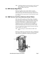
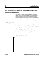
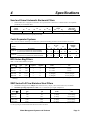
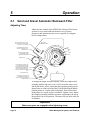
Water Management Systems
Filtration and Separation Systems
SGM-250A Sand and Gravel Filter
CSM Centri Separator
BFS Bag Filter
SWF Full Flow Strainers
Product Manual
Sterling, Inc.
2900 S. 160th Street
New Berlin, WI 53151
Tel [262] 641-8610
Fax [262] 641-8653
Part Number A0568850
Revision C
Bulletin No. SC7-600.4
Sterling/Sterlco is committed
to a continuing program of product improvement.
Specifications, appearance, and dimensions described in this manual
are subject to change without notice.
© Copyright Sterling/Sterlco 2008
All rights reserved.
Effective 4/14/2008
Part No. A0568850
Revision C
Bulletin No. SC7-600.3
Page 2
Water Management Systems and Products
Safety Considerations
Sterling/Sterlco water management systems products are designed
to provide safe and reliable operation when installed and operated
within design specifications, following national and local safety
codes.
To avoid possible personnel injury or equipment damage when
installing, operating, or maintaining this equipment, use good
judgment and follow these safe practices:
; Follow all SAFETY CODES.
; Wear SAFETY GLASSES and WORK GLOVES.
; Disconnect and/or lock out power before servicing or
maintaining the system.
; Use care when LOADING, UNLOADING, RIGGING, or
MOVING this equipment.
; Operate this equipment within design specifications.
; OPEN, TAG, and LOCK ALL DISCONNECTS before
working on equipment. You should remove the fuses and carry
them with you.
; Make sure that system equipment and components are properly
GROUNDED before you switch on power.
; Do not jump or bypass any electrical safety control.
; Do not restore power until you remove all tools, test
equipment, etc., and the system and related equipment are fully
reassembled.
; Only PROPERLY TRAINED personnel familiar with the
information in this manual should work on this equipment.
Water Management Systems and Products
Page 3
Table of Contents
1
Introduction............................................................... 5
1-1
1-2
1-3
1-4
1-5
2
Shipping Information ............................................... 8
2-1
2-2
2-3
2-4
2-5
3
General Description
Sand and Gravel Automatic Backwash Filters
Centri-Separator Filter Systems
BFS Series Bag Filters
SWF Series Full Flow Stainless Steel Filters
Unpacking and Inspection
In the Event of Shipping Damages
If the Shipment is Not Complete
If the Shipment is Not Correct
Returns
Installation............................................................... 10
3-1
3-2
3-3
3-4
Installing the Sand and Gravel Filter
Installing the Centri-Separator System
Installing the BFS Series Bag Filter
Installing the SWF Series Full Flow Stainless Steel Filter
4
Specifications ......................................................... 13
5
Operation................................................................. 14
5-1
5-2
5-3
5-4
Page 4
Sand and Gravel Automatic Backwash Filter
Centri-Separator System
BFS Series Bag Filters
SWF Series Full Flow Stainless Steel Filters
Water Management Systems and Products
1
1-1
Introduction
General Description
Filtration is used on cooling tower systems or chilled water
systems requiring removal of large, heavy-duty suspended solids.
Four filtration systems are available; sand and gravel filters,
centrifugal separators, bag filters, and strainers.
Sand and gravel filters use two layers of gravel and one layer of
sand for filtration. It is piped in a by-pass configuration. A timer
can be preset at any interval to automatically back wash the sand
and gravel. The SGM-250A sand and gravel filter is designed to
handle up to 250 ton tower systems and 500 ton chiller systems.
The Centri-Separator System uses centrifugal force by directing
the water in a circular motion allowing suspended solids to drop
out and be purged from the system. It is piped in a by-pass
configuration and is supplied with an integral pump, electrically
operated ball valve, and controls. A timer can be preset at any
interval to automatically purge the separator. The CSM Centri
Separator is available for cooling tower systems up to 400 tons and
chiller systems up to 800 tons.
BFS bag filters use a 25-micron bag to filter suspended solids in
either a by-pass or full flow piping configuration. A differential
pressure alarm is available to warn when bag is full. BFS bag
filters are available for tower systems up to 150 tons and chiller
systems up to 200 tons.
SWF Series full flow filters use a strainer basket to filter the water.
An 80-mesh strainer screen is standard. Other mesh sizes are
available upon request. The filter housing, strainer basket, and
flanges are made from 304 stainless steel. A differential pressure
alarm and automatic purge valve are available as an option. SWF
Series full flow filters are available for tower systems up to 650
tons and chiller systems up to 850 tons.
Water Management Systems and Products
Page 5
1-2
Sand and Gravel Automatic Backwash Filters
Sterling/Sterlco sand and gravel filters are shipped complete with:
•
Tank
•
Valve manifold
•
Gauges
•
Initial charge of sand and gravel
The system switches valves automatically. Two backwash control
mechanisms are available. Backwash cycles can be based on a time
cycle (SGM-250A) or pressure differential across the unit (SGM250P).
SGM-250A sand and gravel automatic backwash filters are
available in a 250-ton (756,000 Kcal/hr) model for cooling towers
and a maximum-capacity 500-ton (1,512,000 Kcal/hr) chiller
model. The SGM250A model is equipped with automatic valves
operated from a timing device so that the backwash cycle
automatically activates on a periodic basis.
Filters must be installed in a bypass line so that plugging of the
filter or temporary shutdown required for back washing does not
hinder process operation.
1-3 Centri-Separator Filter Systems
Sterling/Sterlco centrifugal separation systems are used on cooling
tower or chilled water systems requiring large capacity, heavy-duty
suspended solids removal.
The Centri-Separator System (CSM-150) is designed to handle up
to 150-ton (567,000 Kcal/hr) cooling tower systems and up to 300ton (907,200 Kcal/hr) chiller systems. The CSM-150 includes a
centrifugal separator, 1/3 hp (0.25 kW) pump, 1/2” PVC electricallyactivated ball valve, and a 115 volt single-phase 60 hertz control
station. The CSM-150 can be mounted on a pump tank or piped in
a bypass line. The system performs all operations, including
separator purging, automatically.
The CSM-400 is designed for larger tower water system
applications; up to 400-ton (1,512,000 Kcal/hr) cooling tower
systems and up to 800-ton (2,419,200 Kcal/hr) chiller systems.
Page 6
Water Management Systems and Products
Note: Centrifugal separation systems must not be used for closedloop or chilled water systems; back flushing eliminates
chemicals added to the system.
1-4 BFS Series Bag Filters
BFS Series bag filters can be used for full flow or bypass
applications. BFS Series filters feature single cell 25-micron
polyester filter bags, and include pressure gauges. BFS bag filters
are available for tower systems up to 150 tons and chiller systems
up to 200 tons.
1-5 SWF Series Full Flow Stainless Steel Filters
SWF Series full flow stainless steel filters feature 304 stainless
steel construction of filter housings, strainer baskets, and flanges.
Maximum working pressure is 100 psi (689.5 kPa/6.9 bars); 150
psi (1,034.5 kPa/10.3 bars) is available. Maximum operating
temperature is 110ºF (43ºC); consult the factory for higher
operating temperatures. 80-mesh screen size is standard for the
stainless steel strainer basket; 40 mesh can be used for cooling
tower water applications. Options include ΔP pressure alarm and
automatic purge valve with timer.
Note: Valving and bypass are not included with SWF Series
filters.
BFS Series and SWF Series full flow filters must be installed with
bypass piping so that plugging of the filter or temporary shutdown
required for back-washing does not hinder process operation.
Water Management Systems and Products
Page 7
2
Shipping Information
2-1
Unpacking and Inspection
You should inspect your Sterling/Sterlco water management
systems and products for possible shipping damage.
Thoroughly check the equipment for any damage that might have
occurred in transit, such as broken or loose wiring and
components, loose hardware and mounting screws, etc. In case of
breakage, damage, shortage, or incorrect shipment, refer to the
following sections.
2-2
In the Event of Shipping Damages
Important!
According to the contract terms and conditions of the Carrier,
the responsibility of the Shipper ends at the time and place of shipment.
The Carrier then assumes full responsibility of the shipment.
; Notify the transportation company’s local agent if you discover
damage.
; Hold the damaged goods and packing material for the
examining agent’s inspection. Do not return any goods to
Sterling/Sterlco before the transportation company inspection
and authorization.
; File a claim against the Transportation Company. Substantiate
the claim by referring to the agent’s report. A certified copy of
our invoice is available upon request. The original Bill of
Lading is attached to our original invoice. If the shipment was
prepaid, write us for a receipted transportation bill.
; Advise Sterling/Sterlco. regarding your wish for replacement
and to obtain an RMA (return material authorization) number.
Page 8
Water Management Systems and Products
2-3
If the Shipment is Not Complete
Check the packing list. The apparent shortage may be intentional.
Back-ordered items are noted on the packing list. You should have:
; Sterling/Sterlco water management system equipment or
chemical treatment products
; Bill of lading
; Packing list
; Operating and Installation packet
; Electrical schematic and panel layout drawings
; Component instruction manuals
Re-inspect the container and packing material to see if you missed
any smaller items during unpacking. Determine that the item was
not inadvertently taken from the area before you checked in the
shipment. Notify Sterling/Sterlco immediately of the shortage.
2-4
If the Shipment is Not Correct
If the shipment is not what you ordered, contact the parts and
service department immediately at [262] 641-8610. Have the
order number and item number available. Hold the items until you
receive shipping instructions.
2-5
Returns
Important!
Do not return any damaged or incorrect items
until you receive shipping instructions from Sterling/Sterlco.
Water Management Systems and Products
Page 9
3
3-1
Installation
Installing the Sand and Gravel Backwash Filter
Selecting an Installation Site
Place the unit on a suitable and level foundation, preferably a
concrete floor or pad and near the pump for best operation. The
location you select must also have an open drain to a sewer for
backwash, a hookup to city water, and a 110-volt electrical source.
Use a fork lift truck when moving the unit to avoid damage.
Installing the Unit
Be sure that piping to the unit has a bypass circuit. The bypass
circuit allows for removal of the unit for servicing without
interrupting water service. Always run piping full size at 1½” NPT
(approx. 38 mm). Connect the entering water connection of the
filter unit to the process supply and the leaving connection to the
tank. Use 2” NPT (approx. 51 mm) to hook up city water or
process water to the backwash connector piping, as well as to
connect back-flush connections to the city waste or sewer.
Figure 1
Typical Sand and Gravel Filter
Page 10
Water Management Systems and Products
Filling the Unit
Fill the water tank with water by opening valves e and f. Valves
c, d, g, and h are automatically controlled by a timer. After you
open valves e and f, water flows and is filtered in the normal
direction.
Take a moment now, while the filter is clean, to record pressure
gauge readings at the inlet and outlet of the filter. You’ll use these
readings later to determine the cleanliness of the filter media.
Complete the installation of the sand and gravel filter by plugging
the unit into a 110-volt source of electricity. The sand and gravel
filter is now ready to use.
3-2
Installing the Centri-Separator System
Selecting an Installation Site
Place the unit on a suitable and level foundation, preferably a
concrete floor or pad and near the pump for best operation. The
location you select must also have an open drain to a sewer for
purging and a 110-volt electrical source.
Use a fork lift truck when moving the unit to avoid damage.
Installing Piping
Be sure that piping to the unit has a bypass circuit. The bypass
circuit allows for removal of the unit for servicing without
interrupting water service. Part of your Centri-Separator system
includes a three foot (about 1 m) suction leg, including a priming
valve/connection for startup. Connect the pump suction leg to the
pump suction connection. Sterling/Sterlco recommends that you
use a hose at least 1½” (about 38 mm) in diameter for clean water
flow to the pump tank. Your system includes a threaded barbed
fitting and clamps to install the hose.
Priming the Pump and Preparing for Operation
Be sure that the pump on your Centri-Separator system is primed
before you start up the system. To do this, connect a city water line
to the priming valve. Allow enough time for the suction leg to fill
with water, then close the priming valve.
Water Management Systems and Products
Page 11
Complete the installation of your Centri-Separator system by
plugging the unit into a 110-volt source of electricity. The CentriSeparator system is now ready to use.
3-3
Installing the BFS Series Bag Filter
Selecting an Installation Site
Place the unit on a suitable and level foundation, preferably a
concrete floor or pad and near the pump for best operation.
Use a fork lift truck when moving the larger units to avoid damage.
Installing Piping
Be sure that piping to the unit has a bypass circuit. The bypass
circuit allows replacement of bag filter without interruption of
service. Connect to the inlet and outlet as labeled on filter housing.
Solids will collect inside the bag filter preventing spill over when
the bag is removed. Always run piping full size. Filter housing
maximum operating pressure is 150 psi.
3-4
Installing the SWF Series Full Flow Stainless
Steel Filter
Selecting an Installation Site
Place the unit on a suitable and level foundation, preferably a
concrete floor or pad and near the pump for best operation.
Use a fork lift truck when moving the larger units to avoid damage.
Installing Piping
Be sure that piping to the unit has a bypass circuit. The bypass
circuit allows for removal of the unit for servicing without
interrupting water service. Connect to the inlet and outlet as
labeled on the housing. Solids will collect in the bottom of the
housing where it will be purged out of the system. Always run
piping full size. Filter housing maximum operating pressure is 100
psi.
Page 12
Water Management Systems and Products
4
Specifications
Sand and Gravel Automatic Backwash Filters
•
Model SGM-250A is equipped with automatic valves operated from a time device so that backwash is accomplished
periodically on an automatic basis.
Model
number
SGM-250A
L
in.
40
Dimensions in. (cm)
W
in.
cm
cm
101
48
122
Shipping
weight
lbs.
Kg
1,800
818
H
in.
39
cm
99
Pressure
differential
backwash c
SG-250P
c Model SGM-250P. Automatic valves are operated from pressure switch. Pressure switch monitors the pressure drop in the filter
media and activates backwash cycle at preset pressure drop.
Centri-Separator Systems
Note: Not to be used for closed-loop or chilled water systems; back flushing eliminates chemicals added to the system.
Model
number
CSM-150 •
•
CSM-400 •
•
L
Description
150-ton (453,600 Kcal/hr) tower maximum
300-ton (907,200 Kcal/hr) chiller maximum
400-ton (1,209,600 Kcal/hr) tower maximum
800-ton (2,419,200 Kcal/hr) chiller maximum
in.
29
29
26
26
cm
74
74
66
66
Dimensions
in. (cm)
W
H
in. cm
in.
cm
19½ 50
26 66
19½ 50
26
66
20
51
41
104
20
51
41
104
Shipping
weight
lbs.
Kg
130
60
130
60
150
69
150
69
BFS Series Bag Filters
Note: Can be used for full flow or bypass.
Model c
BFS-30
BFS-65
BFS-90
BFS-200
BFS-300
BFS-450
Max. flow
gpm
lpm
30
113
65
246
90
340
200
757
300
1,135
450
1,703
No. filter bags
required
supplied
1
3
1
3
1
3
1
3
2
6
3
12
Pipe size
inches
1½” NPT
2½” NPT
2½” NPT
3” (flanged)
4” (flanged)
5” (flanged)
mm
38 mm
63 mm
63 mm
76 mm (flanged)
102 mm (flanged)
127 mm (flanged)
c Single cell filters include bypass, pressure gauges and 25 micron filter bags. Multi-cell filters include pressure gauges and 25 micron
filter bags.
SWF Series Full Flow Stainless Steel Filters
•
•
Maximum working pressure is 100 psi (689.5 kPa/6.895 bars); 150 psi (1,034.25 kPa/10.343 bars) is available.
Maximum operating temperature is 110ºF (43ºC). Consult factory for higher temperatures.
Maximum flow
Model cd
SWF-100
SWF-200
SWF-350
SWF-750
SWF-1300
SWF-2000
gpm
100
200
350
750
1,300
2,000
lpm
378
757
1,325
2,839
4,920
7,570
Connection size/flange
inches
mm
2” flange
51 mm flange
3” flange
76 mm flange
4” flange
102 mm flange
6” flange
152 mm flange
8” flange
203 mm flange
10” flange
254 mm flange
c 80 mesh screen size is standard for stainless steel strainer basket. 40 mesh can be used for tower water. Specify mesh size.
d Valving and bypass are not included with SWF Series stainless steel filters.
Water Management Systems and Products
Page 13
5
Operation
5-1
Sand and Gravel Automatic Backwash Filter
Adjusting Timer
Adjust the time control of the SGM-250A if desired. The factory
set timer is set to backwash four minutes every 24 hours.
Frequency and duration may be reset as required. See diagram
below to adjust timer.
M AN UAL
For manual regeneration, move
lever in direction of arrow as far
as it will go - then release.
REGEN ERA TIO N
Red
Dial
1. Set skipper wheel so that
"TO-DAY" or number one is
opposite arrow.
White
Dial
Lift tabs on skipper wheel
corresponding to days
regeneration as desired.
Yellow
Dial
Skipper wheel.
E
R A T IO N
TI
G
NE
E
RE
M
2. Set time of day at which unit
is to regenerate by loosening
this screw, and turning this dial
in either direction so that arrow
points to desired regeneration
time in the window of the black
dial.
DAY
Then tighten screw.
T IM
E O F D AY
3. Set time of day by lifting up
yellow dial and turning it in
either direction until actual time
is opposite arrow.
To change the length of backwash time, rotate the complete dial
assembly until the red arrow is at 11:00. Loosen the center screw
and lift the black, yellow, and white dials together pointing to the
desired time to on the red scaled dial. Lift the black knob and the
red dial pointer to 6 on the white-scaled dial. Then lift the black
knob pointer to 6 on the yellow-scaled dial. Tighten screw. Rotate
the complete assembly until the red arrow is pointing to the rib on
the pressure box (6:00 position). The timer will now back wash for
six minutes.
Important!
Make sure gears are engaged before tightening screw
Page 14
Water Management Systems and Products
The Model SGM-250P backwashes based upon pressure
differential across the filter media. Additionally, an adjustable
timer allows back washing for up to five minutes. The factory
setting is four minutes.
The pressure differential switch is adjustable for pressure drop and
dead band. Backwash will start when the pressure differential
reaches set point plus the dead band. For example, if the pressure
differential is set for 6 psi, the dead band for 4 psi, and the
backwash timer for 4 minutes, then the backwash cycle will start at
10 psi for a duration of four minutes.
Replacing Sand and Gravel
Replace the sand and gravel every two years, when contaminated,
or when sand has carried over from excessive water flow.
There are three layers of filter media. First, starting from the
bottom, place 200 lbs. of ½” x ¼” round gravel. Second, place 300
lbs. of ¼” x 1/8” round gravel and third, the top final layer, place
700 pounds of #20 filter sand.
Anode Replacement
On top of the filter housing is a sacrificial anode made of
magnesium. Inspect and replace when it has depleted.
5-2
Centri-Separator System
The CSM-150 and CSM-400 require a 120/1/60-power source and
are provided with a standard plug. The separators are designed to
operate to a prescribed flow range for maximum solid removal.
The CSM-150 operates at a flow rate of 10 to 20 gpm and the
CSM-400 operates at 45 to 70 gpm. Liquid enters the upper portion
of the separator housing tangentially and the solids are drawn
through internal slots to the bottom chamber. An electrically
operated ball valve automatically back flushes the solids from the
separator. Periodically inspect and ensure that the purge line is
clear to flow freely.
Water Management Systems and Products
Page 15
5-3
BFS Series Bag Filters
Bags are easily removed from the top of the filter housing. Before
removing the bag filter be sure that pressure has been relieved and
that the filter housing has been isolated to prevent spill over.
! CAUTION
SEVERE INJURY WILL RESULT IF HOUSING COVER IS REMOVED UNDER
PRESSURE. RELIEVE PRESSURE AND ISOLATE HOUSING BEFORE
REMOVING COVER.
Loosen and unlatch the V-clamps or swing type bolts that fasten
down the top of the filter housing. The top is hinged on one end
and will swing open. Reach down and lift the bag handle and
remove the filter bag. Unfold and install the new bag. Close the
cover and tighten down the swing bolts.
5-4
SWF Series Full Flow Stainless Steel Filters
Periodically, solids that settle to the bottom of the filter housing
will need to be purged out. The drainage port valve, which is piped
to an open drain, will need to be opened to purge the debris from
the reservoir. Over time, one should be able to accurately
determine how often the valve should be opened. Do not allow the
debris to collect beyond the capacity of the reservoir.
An optional automatic purge valve is available to open based upon
an adjustable time cycle. Periodically inspect and ensure that the
purge line is clear to flow freely.
! CAUTION
SEVERE INJURY WILL RESULT IF HOUSING COVER IS REMOVED UNDER
PRESSURE. RELIEVE PRESSURE AND ISOLATE HOUSING BEFORE
REMOVING COVER.
The cover of the SWF full flow filter is removable if the strainer is
clogged with debris. A pressure drop of 10 psi, after purging debris
from the reservoir, would indicate that the strainer requires
cleaning. Do not remove the cover under pressure. Relieve the
pressure and isolate the filter from the system first. Lift the strainer
element out of the filter housing and scrub it carefully with a rigid
nylon brush and water until clean. Wash it off with clean water,
Page 16
Water Management Systems and Products
preferably a garden hose if possible. Return it to the filter housing
ensuring that the U-shaped gasket fits securely to the bottom of the
strainer. Make sure that the strainer head gasket is secure.
Reposition the strainer cover on top of the filter housing.
On those models with a band clamp, replace the band clamp
around the strainer cover and housing latching the T-bolt. Then
push the latch handle towards the filter housing. The T-bolt latch
does not need adjustment when installed. It is set at the factory for
proper clamp compression.
Bolted cover models require a torque sequence as follows: 12:00 to
6:00, 3:00 to 9:00, 11:00 to 5:00, and 2:00 to 7:00. Bolt torque
requirements are: 3/8” bolts (15 to 25 ft.lbs.), ½” bolts (45 to 55
ft.lbs.), and 5/8” bolts (80 to 100 ft.lbs.).
Service Notes
Water Management Systems and Products
Page 17
Parts Department
Call toll-free 7am–5pm CST [800] 423-3183 or call [262] 641-8610 or fax [262] 641-8653
The ACS Customer Service Group will provide your company with genuine OEM quality parts manufactured to
engineering design specifications, which will maximize your equipment’s performance and efficiency. To assist in
expediting your phone or fax order, please have the model and serial number of your unit when you contact us. ACS
welcomes inquiries on all your parts needs an is dedicated to providing excellent customer service.
Service Department
Call toll-free 8am–5pm CST [800] 423-3183 or call [262] 641-8610
Emergencies after 5pm CST, call [847] 439-5655
We have a qualified service department ready to help. Service contracts are available for most of our products.
www.acscustomerservice.com.
Sales Department
Call [262] 641-8610 Monday–Friday, 8am–5pm CST
Our products are sold by a world-wide network of independent sales representatives. Contact our Sales Department
for the name of the sales representative nearest you.
Contracting Department
Call [262] 641-8610 Monday—Friday, 8am—5pm CST
Let us install your system. The Contracting Department offers any or all of these services: project planning; system
packages including drawings; equipment, labor, and construction materials; and union or non-union installations.
Sterling/Sterlco
2900 S. 160th Street
New Berlin, WI 53151
[262] 641-8600 • Fax [262] 641-8653
www.sterlco.com
Page 18
Water Management Systems and Products