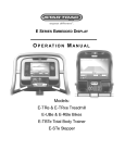
1
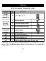
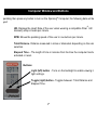
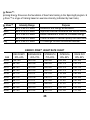
Star Trac Fitness™
Spinning® Computer
User Manual
Installation, Service and Instructor Education
Table of Contents
FCC Regulatory Statements _________________________________________________
Parts List _______________________________________________________________
Marketing Statement Regarding Heart Rate ____________________________________
Specifications ____________________________________________________________
How it Works ____________________________________________________________
Computer Window and Buttons ______________________________________________
Installing or Replacing Batteries______________________________________________
Do I need to Re -sync? _____________________________________________________
Testing for RPM _________________________________________________________
Syncing Mode ___________________________________________________________
Setup Mode_____________________________________________________________
Installation of Cadence Sensor and Magnet – All Spinners® _______________________
Mounting Computer On Handlebars - V-Bikes ________________________________
Mounting Computer On Handlebars - Pro 5800 / 6800 / Elite 5900 __________________
Mounting Computer On Handlebars - Elite 6900 and NXT 7000 ____________________
Maintenance Checklist____________________________________________________
FAQ’s and Troubleshooting ________________________________________________
Spinning® Instructor Education_____________________________________________
FCC Regulatory Statements
1.
This device complies with Part 15 of the FCC Rules. Operation is subject to the following
two conditions: (1) this device may not cause harmful interference, and (2) this device
must accept any interference received, including interference that may cause undesired
operation.
2.
Changes or modifications not expressly approved by Star Trac could void the user’s
authority to operate the equipment.
1
Parts List
®
All 727-0083 Spinning Computer Kits include:
Part Number for
re-order
Qua
ntity
727-0083
Spinning ®
Computer Kit
1
Spinning Computer
1
Mounting Bracket
1
V2 Bracket Mounting Insert
1
Pro Bracket Mounting Insert
727-0084-KT
1
Cadence Sensor
727-0094
N/A
N/A
N/A
N/A
N/A
1
4
1
1
1
1
Cadence Magnet
AA Panasonic Batteries
®
Spinning Computer Manual
M5 Allen Assembly Tool
M2 Allen Assembly Tool
M6x30 Computer Clamp Screw for Rhino Horn
727-0093-KT
Mounting
Bracket Kit
Description
®
®
efore installing the Spinning Computer, verify that all the parts needed for mounting on your bikes
e included. If any of the items are missing, call StarTrac at 800-503-1221 or 1-714-669-1660 to
der a replacement kit.
2
Marketing Statement Regarding Heart Rate
arketing Statement Regarding Heart Rate Acquisition on the Star Trac Spinning® Computer:
tar Trac takes the acquisition and accuracy of heart rate very seriously and has developed a system to
erform to the best ability that technology will allow. Star Trac has engineered a product that has taken
very precaution possible to acquire an accurate heart rate signal as well as eliminate “crosstalk”
terference that may be caused by other monitors being placed too close together.
o achieve the best possible results from your Spinning® Computer, please abide by the following
mportant parameters:
Users must wear Coded Transmitters (such as Polar© T61, Polar© T31C or Polar© WearLink
when operating the Spinner® bike with the Spinning® Computer. Only Coded Transmitter will allo
a “one to one” relationship with the Spinning® Computer and will minimize potential “crosstalk”
interference. If users wear non-coded straps, there is significantly increased potential for
“crosstalk” which will cause erratic heart rate display , loss of heart rate display and significantly
reduce the consistency of accurate heart rate reporting.
Bikes should be spaced so that the side-to-side distance from the Spinning® Computer on one
bike and the Spinning® Computer on bikes to the left or right is at least 36 inches (91.4 cm). In
addition, the distance from the bottom of the Spinning® Computer on one bike to the seat of the
bike in front of it (where another rider and his/her transmitter would be seated) should be at least
24 inches (61 cm) in order to significantly reduce chances for interference. See the diagram on
page 21 regarding bike layout.
3
3) Riders must lean into the
display (within 16 inches) and
wait for the HR to display –
once the HR is displayed they
must maintain the forward
Position for 15 seconds while
the computer codes with their
Polar Coded Strap, this insures
that no outside signals will interfere
with the riders data once they lean
back into their seated position.
Calorie calculations are displayed as a summary only and will ONLY be shown if a user utilizes a
heart rate strap throughout the entire workout.
Cell phones, televisions, speakers and other electronic devices can cause interference with the
operation if they are in close proximity to the Spinning® Computer and/or transmitter.
there are any questions regarding operation or usage of the Spinning® Computer, please contact
tar Trac Customer Support at 800-503-1221 or 1-714-669-1660.
4
Specifications
Computer:
Heart Rate Range:
Battery:
Battery life expectancy:
Approximately 30” From computer to users HR chest strap
Qty 4 each AA Alkaline
1 year (depending on use and backlight usage)
Cadence Sensor:
Battery:
Battery life expectancy:
Distance to magnet:
Lithium CR2032
Approximately 2.5 Years (depending on use)
Approximately 5mm
5
How it Works
How does the Spinning computer work?
he Spinning computer displays heart rate, RPM (speed), total distance and elapsed time.
•
•
©
©
©
The heart rate information is received from a Polar T61, Polar T31C or Polar
®
WearLink heart rate strap worn by the person riding the Spinning Bike. The Polar stra
sends a radio signal to the computer and the computer displays the person’s heart rate
If any other strap is used it will not display the heart rate. The computer and heart rate
strap must be within range of each other and no other heart rate strap can be within this
imaginary circle. The range is approximately 36 inches from the computer.
The RPM signal is transmitted by the cadence sensor sending the RPM to the compute
Each time the magnet on the flywheel passes the cadence sensor it records one
revolution and as it counts the revolutions it sends this number to the computer.
Heart
rate
RPM
6
Computer Window and Buttons
®
tart pedaling then press any button to turn on the Spinning Computer; the following data will be
splayed:
®
HR- Displays the Heart Rate of the user when wearing a compatible Polar HR
telemetry strap in beats per minute.
RPM- Shows the pedaling speed of the user in revolutions per minute.
Total Distance- Distance measured in miles or kilometers depending on the setup
selection.
Elapsed Time – The length of time in minutes from the time the computer has been
activated or reset.
Buttons:
Light (left) button - Turns on the backlight to enable viewing in low
light settings.
Toggle (right) button - Toggles between: Total Distance and
Elapsed Time.
7
Installing or Replacing Batteries
me required:
5 Minutes
arts required:
4 new AA alkaline batteries
ools required:
Slotted or Phillips screwdriver
Low Battery
Indicator
ote: The batteries in the computer will last approximately
year depending on usage.
he cadence sensor battery will last approximately 2.5
Remove the computer from the handlebar or computer mounting
bracket.
Loosen the captive screw on the back of the battery cover (screw will
not completely come off, it will remain captive.) To remove the cover,
pull on the captive screw and lift.
Install 4 new batteries. Note: Replace all 4 batteries at the same time.
8
Installing or Replacing Batteries – cont’d
Note the directions each battery is to be installed. There is a plus (+) and minus (-) symbol
inside the battery compartment. The + sign indicates the positive (+) side on the battery and
the - indicates the negative (-) side on the battery.
Insert each of the 4 batteries into the battery compartment of the computer.
Attach the battery cover and tighten the screw.
Attach the computer onto the handlebar or computer mounting bracket and test.
9
Do I need to Re-sync?
: Syncing will not improve Heart Rate and is not a calibration it should only be used to Sync
Pair up) the cadence sensor and the computer so that RPM can be transmitted.
erform the Syncing process after checking all of the following:
•
•
•
•
•
Do the serial numbers on the cadence sensor and the
computer match?
o If they do not match the handlebar has been swapped
with another bike and should be swapped back, so the
computer and sensor are matched up again.
Is the battery secure in the cadence sensor and the cover is not loose?
o A loose battery will prevent the cadence sensor to transmit the RPM signal to the
computer.
Is the magnet aligned with the cadence sensor?
o A missing magnet or one that is not lined up properly will prevent the cadence senso
to transmit the RPM signal to the computer.
Does the computer turn on when you press a button?
o If the computer does not turn on replace the batteries in the computer.
The computer turns on but as you pedal it does not show the RPM.
o If you have performed all of the above steps you may now sync the computer and
cadence sensor. This will make them a paired set and will be able to transmit and
receive the RPM signal.
10
Testing for RPM
me required:
Less then 5 Minutes
arts required:
N/A
ools required:
N/A
TEST Procedure:
Once the batteries are installed, press any button and the display window will turn on in the
Workout mode.
Test by waving a magnet across the cadence sensor. If you see RPM
values, then the cadence sensor and computer was synced successfully,
there is no need to perform the sync process.
If you do not get any rpm reading and the computer turns off you WILL
need to perform the Syncing process.
NOTE: If the cadence sensor and computer are no longer a pair (i.e. when users swap
handlebars with the computer attached.) the Cadence sensor and computer will have to be
sync’d again. Do not swap handlebars.
AUTION: TEST ONE BIKE AT A TIME, the range for the cadence sensor is
pproximately 30 feet and if you are testing the bike and someone else o n the same
oom is pedaling another bike you may be picking up the wrong RPM signal.
11
Syncing Mode
yncing Process:
ools required:
Coin (penny, dime, etc.) or similar item to remove battery cover
teps to Syncing:
®
Removing the battery lid on the backside of the Spinning Computer and insert or replace th
4 AA batteries.
2. Once the batteries are installed, press any button and the display window will go into the
orkout mode.
Workout Mode
window
Holding the cadence sensor, remove the battery cover from the back of the cadence sensor
using the coin or similar object and take out the battery.
AUTION: SYNC ONE BIKE AT A TIME, the range for the cadence sensor is
pproximately 30 feet and if you are testing the bike and someone else on the same
oom is pedaling another bike you may be picking up the wrong RPM signal.
12
Syncing Process – cont’d
4. Place the battery back in the cadence upside down to reset the system. Do not put the lid
back on yet.
Battery facing
upside down →
Battery facing
← right side up
5. Activate Sync Mode on the computer by holding down the Light
and Toggle buttons for several seconds until the window displays
“Conn“
Sync
Mode
window
6. Remove the cadence sensor battery and place it back in correctly (battery face will be right
side up).
7. Replace the battery cover on the cadence sensor.
Note: To put the cadence sensor battery cover on
correctly, align the arrows before locking shut.
13
Syncing Process – cont’d
8.
With the computer window still displaying “Conn” hold the magnet
about 1/2 inch (1.2 cm) away from the edge of the cadence sensor
with the large arrow pointing towards the magnet.
Wave the magnet back and forth several times until the window on
the computer displays a random ID number (e.g. ID 45896).
Finally, accept ID by pressing the Toggle (right) button.
10. Once the Syncing Process is done, the display should be in the Workout Mode.
Wait for 60 seconds.
You must wait for 60 seconds to allow the computer to reset the ID properly.
12. Test for response by turning the computer on then waving a magnet across the cadence
sensor, as you did in the test on page 10. By doing this you are simulating the same motion
as when the flywheel rotates and the magnet passes by the cadence sensor. If you see RPM
displayed, then the cadence sensor and computer were synced successfully. Proceed with
the installation and mounting to the bike.
NOTE: Remember to keep the computer and cadence sensor as a set at all times.
14
Setup Mode
®
Spinning Computer is pre-set with a gear ratio 2 and a setting display distance in miles. It is
so pre-set with recommended default settings for the length of time the backlight will stay on when
ctivated and the length of time summary information will be displayed. You can make changes to
ese settings by following the steps below. (You will first need to install 4 AA batteries in the
omputer.) Any time you want to change setting or view information, follow these Setup Mode steps
o activate Setup Mode:
1. Press any button to activate computer.
®
2. Wave a magnet along the right side of the Spinning Computer until
the display window shows all LCD segments flash.
3. Press Toggle (right) button to scroll through available setup options.
4. Press the Light (left) button to change settings on the current display option.
etup Mode options:
•
GEAR and Software Version
o Gear Ratio, Select 1 (2.875) for V-Bikes.
o Select 2 (3.250) for all other models.
o Software Version displayed (-XX)
(Default Setting)
Note: User will not get the correct RPM values if
the Gear Ratio setting is not correct.
15
Setup Mode- cont’d
•
Units - MILES or KM
Note: User will not get the correct RPM values if
the Gear Ratio setting is not correct.
(Default Setting)
•
BLON – (Default Back Light On*) The amount of time the backlight
will stay on when the left button is pressed. Select between 1
second to 60 seconds using the Light (left) button and press the
Toggle (right) button to save and advance to the next setting.
*Note: Increasing the BLON (Back Light On) time will reduce
overall battery life. A shorter BLON time will result in longer
battery life (recommended).
•
BLU – (Back Light Usage) Total time in minutes that the back light
has been on since the last data clearing. Press the Light (left)
button to clear data, if desired, then press Toggle (right) button to
accept and advance to the next setting.
16
Setup Mode- cont’d
•
UH – (Usage Hours) Total operation time in hours of display since
the last data clearing. Press the Light (left) button to clear data, if
desired, then press Toggle (right) button to accept and advance to
the next setting.
•
ODO – Total Miles / KM
Total traveled distance in miles or KM since the last data clearing.
Press the Light (left) button to clear data, if desired then press the
Toggle (right) button to accept and advance to the next setting.
•
SON – (Summary ON Time) Number of seconds the summary will
be displayed at the end of the workout.
o Options: 30, 60, 90, or 120 seconds
Select by using the Light (left) button and press the Toggle
(right) button to accept and exit Setup Mode.
5.
To exit Setup Mode, press the Toggle (right) button several times until the computer
returns to Workout Mode.
6.
Once out of Setup Mode and in the Workout Mode, one could start monitoring the
workout.
17
Installation of Cadence Sensor and Magnet – All Spinners®
Before the cadence sensor is securely fastened to the flywheel support, it must be adjusted
so that it is about 5 mm (.20 in) from the magnet face. Install the magnet on the flywheel so
that it aligns with the arrow on the end of the cadence sensor. Note the distance between th
end of the cadence sensor and the magnet face. Remove the cadence bracket and adjust
the distance by pulling or pushing the cadence sensor bracket.
Tighten the set screw on the cadence mounting bracket using the M2 Allen tool
Caution
Do not over tighten the set screw.
Magnet location
Remove the backing of the adhesive on the magnet. Mount the magnet with the adhesive
tape side onto the flywheel by positioning the magnet so it will line up in front of the cadence
sensor as the flywheel turns. Note: Mount the magnet near one of the dots of the Spinning
logo as shown in the figure above.
18
Mounting Computer On Handlebars - V-Bikes
me required:
15 Minutes
arts required:
®
727-0083 Spinning Computer Kit
NOTE: The thick insert is used on the V-Bikes
ools required:
M5 Allen Wrench
M2 Allen Wrench
Place the thick insert inside the bottom part of the
Mounting Bracket Clamp. Position the mounting
bracket onto the center-curved portion of the handlebars. Once positioned correctly, tighten
the 4 M6x20 screws using the M5 Allen tool.
Install the computer onto the mounting bracket by
sliding the computer clamp over the long portion of the
bracket. Tighten computer clamp with the M6 screw
and nut using the M5 Allen tool.
Note: Use the M6x30 screw for the computer
clamp when installing onto the computer
mounting bracket.
19
Mounting Computer On Handlebars - Pro 5800 / 6800 / Elite 5900
me required:
15 Minutes
arts required:
®
727-0083 Spinning Computer Kit
Note: The thin spacer is used on Pro 5800 / 6800 and
Elite 5900 bikes.
ools required:
M5 Allen Wrench
M2 Allen Wrench
Place the thin insert inside the bottom part of the
Mounting Bracket Clamp. Then position the mounting bracket onto the center-curved portion
of the handlebars. Once positioned correctly, tighten the 4 M6x20 screws using the M5 Allen
tool.
Install the computer onto the mounting bracket by
sliding the computer clamp over the long portion of the
bracket. Tighten computer clamp with the M6 screw
and nut using the M5 Allen tool.
Note: Use the M6x30 screw for the computer
clamp when installing onto the computer
mounting bracket.
20
Mounting Computer On Handlebars - Elite 6900 and NXT 7000
me required:
15 Minutes
arts required:
727-0083 Spinning® Computer Kit
Note: The inserts and mounting
bracket are not used on the
Elite 6900 or NXT 7000.
ools required:
M5 Allen Wrench
M2 Allen Wrench
1.
Install the mounting bracket to the center flat
section of the handlebar by slightly prying the
computer bracket clamp open.
2.
Secure clamp down by tightening the M6x20 screw
and M6 nut.
21
Maintenance
Checklist
FAQ’s
Preventative
and Troubleshooting
Maintenance
tar Trac strongly recommends performing the regular daily, weekly and monthly preventive
aintenance routines outlined below. If any items need replacement contact the Star Trac Custome
upport Department at 800-503-1221 or 1-714-669-1660.
Daily W= Weekly M= Monthly
W
M
Procedure
Daily maintenance of the computer will determine its life of the computer by how consistently it is
performed.
•
Wipe down the computer with a soft cloth after each use.
•
Dilute Simple Green (1) with water (30) (30:1 ratio) spray onto a soft cloth then wipe the Spinner
Computer.
NOTE: Never spray directly onto the Spinner Computer.
•
Never use abrasive cleaning liquids or oil base, ammonia or alcohol when wiping down the computer
The w eekly maintenance should focus on the overall performance of the computer. During this portion o
the maintenance look for vibration and possible loose assemblies.
•
Inspect each computer f or loose parts, bolts and nuts. Adjust as necessary.
•
Remove any computers that are not properly mounted and are deemed unsafe.
P
P
P
P
P
P
The monthly maintenance check should be a comprehensive inspection of the overall assembly
components of the computer.
•
Inspect all areas for proper adjustments
•
Inspect all parts to determine damage which will require possible part replacement.
•
Battery Low will display when the battery needs replacement. Replace the batteries in the computer
with 4 high quality AA Alkaline batteries such as Duracell or Energizer.
•
Inspect the mounting of the cadence sensor and magnet to insure it is intact and working properly.
ote: Depending on the amount of use, some procedures may need to be performed more frequentl
No display
22
o
o
o
Press any button.
Pedal the bike and then press any button.
Check batteries in computer.
No heart rate
o Is the user wearing a Polar® “Coded” HR chest strap?
o Moisten the strap and wear it against the skin.
o The battery in the strap might be low, try another strap.
o Stay in Syncing position for 15 seconds. Note: It may take 15 seconds (or more)
the computer to obtain a heart rate signal from a chest strap.
Heart rate drops out
o Rider may not have held forward position for 15 seconds.
o Rider does not have the recommended “Coded” chest strap or it may not be working
®
Which heart rate strap works with my Spinning Computer?
o Any Polar® “Coded” HR strap. Note: It is suggested to use a Polar® “Coded” series
chest strap to reduce HR “crosstalk”.
Picking up another riders heart rate
o Bikes might be too close to each other and receiving HR from another rider. Move
the bikes so there is more space from the computer of your bike to the chest of the
other rider (see diagram on page 22).
o Each rider should wear a Polar® “Coded” series chest strap.
23
FAQ’s and Troubleshooting – cont’d
Battery light does not stay on long enough
o Change the BLON time (see page 6).
No RPM
o Is the magnet on the left side of the flywheel and aligned with the cadence sensor
o Sync up the computer and cadence unit and wait 60 seconds.
o Check the battery in the cadence sensor.
o If pedaling exceeds 120 RPM, the computer will flash the 120 value until rpm’s
decrease.
What is the battery life?
o Computer batteries last approximately 1 year depending on usage and backlight use
Note: “Low Batt” will be displayed underneath the Heart symbol, suggesting battery
replacement.
§ Computer batteries: 4 AA Alkaline
§ Cadence sensor battery: Lithium CR2032
o Cadence sensor battery lasts approximately 2.5 years.
What does the computer display?
o Cadence = RPM
o Heart Rate = BPM
o Total Distance = MILES / KM
o Elapsed Time = MINUTES
Total Calories = kCal
24
Spinning® Instructor Education
Instructor Education
adence, Resistance And Intensity:
nderstanding the relationship between cadence, resistance and intensity is the key to Spinning®
ogram classes that meet training goals. By using the Spinner® computer, you will become more
oficient at increasing power, gaining efficient leg speed and mastering the relationship between
eal resistance and heart rate intensity.
eart Rate Monitoring:
efore discussing cadence and how to use the Spinning® Computer effectively, one needs an
nderstanding of heart rate monitoring. Heart rate monitors are used in the Spinning® program for
ontinuous feedback on exercise intensity. For effective training, it is desirable sometimes to exercise
anaerobic intensity and aerobic intensity at some other times. Heart rates are used to tell whether
erson is in aerobic or anaerobic intensity. Generally speaking, when heart rate is between 65 %
0% of one’s maximum heart rate (MHR) it is aerobic, and is anaerobic when the heart rate is above
0%.. An easy way to estimate one’s maximum heart rate is to use the age-predicted formula: 220
ge. Subtract one’s age from 220 to get age-predicted maximum heart rate. For example, a 30 years
d has 220 – 30 to get age-predicted maximum heart rate of 190 beats per minute (BPM).
25
nergy Zones™:
he Spinning Energy Zones are the foundation of heart rate training in the Spinning® program. Each
nergy Zone™ is a type of training based on exercise intensity (indicated by heart rate).
Energy Zone™
covery
ndurance
trength
terval
ace Day
Intensity Range
50% to 65% of MHR
65% to 75% of MHR
75% to 85% of MHR
65% to 92% of MHR
80% to 92% of MHR
Purpose
Relaxation and energy accumulation.
Improves muscular endurance and mental stamina.
Raises metabolism, burns fat, increases energy.
Trains the heart to recover quickly from work effort.
To challenge the well conditioned exerciser.
ENERGY ZONE™ HEART RATE CHART
AGE
20-23
24-27
28-31
32-35
36-39
40-43
44-47
48-51
52-55
56-60
RECOVERY
50%-65%
100-129
98-126
96-123
94-120
92-118
90-116
88-113
86-110
84-108
82-105
ENDURANCE
65%-75%
129-149
126-146
123-143
120-140
118-137
116-134
113-131
110-128
108-125
105-122
STRENGTH
75%-85%
149-168
146-165
143-162
140-159
137-155
134-151
131-148
128-145
125-141
122-139
26
INTERVAL
65%-92%
129-182
126-178
123-175
120-172
118-168
116-164
113-161
110-157
108-153
105-150
RACE DAY
80%-92%
160-182
155-178
153-175
150-172
146-168
143-164
140-162
137-157
133-153
131-150
CADENCE FUNDAMENTALS
What Is Cadence?
adence is defined as the number of times the pedals revolve per minute, also known as RPM f
volutions per minute. The safest, most efficient and most realistic cadences are 80–110 RPM for a
at road and 60–80 RPM for a hill. These ranges are based on studying the cadences of elite cyclist
s well as understanding how the muscles work together to turn the pedals in the most efficient
anner.
adence Range for Flat Roads: 80-110 RPM.
edaling faster than 110 RPM is both unrealistic and counterproductive. The resistance knob on a
pinning® bike is used to increase friction on the flywheel in order to simulate realistic external force
would encounter on an outdoor bike, such as road surfaces, bike weight and wind resistance.
edaling Faster Than 110 RPM Is Unrealistic because:
It’s like pedaling very fast in a very low gear—there’s a low power to resistance ratio.
It’s wasted energy. If a person pedaled like this on street bike, he/she wouldn’t generate
much power or speed.
A skilled cyclist who has worked on her pedal stroke for many years and has trained the
nervous system to react quickly is able to pedal efficiently at 100+ rpm for an extended
period. Because of his/her strength and ability to overcome the higher resistance at faster leg
speeds, it is said that he/she has a high power to resistance ratio.
edaling Faster Than 110 RPM Is Counterproductive because:
No amount of high-cadence/low-resistance pedaling on a Spinning® bike will succeed at
training the nervous system properly. The flywheel is doing most of the work.
One won’t achieve his/her performance and weight loss goals.
One won’t build leg strength.
27
It Good To Pedal Faster Than 110 RPM?
hose who have a high power to resistance ratio may occasionally attain these leg speeds. This
eans they have the ability to overcome resistance through strength and speed. The rare, highly
killed Spinning® enthusiast (often cyclists) who have mastered a smooth pedal stroke and who
nderstand the dynamics of cadence can pedal faster than 110 rpm for 1-3 minutes. A high
erformance sprint, used judiciously in ride profiles may require cadences over 110 rpm for 10-20
econds.
ouncing In The Saddle:
When riding at cadences of 100-120 rpm with too little resistance, the rider will bounce in the saddle.
What causes the bouncing has to do with the pedal stroke. There are four phases to the pedal stroke
any riders, however, usually have only one phase—straight down. That means that they haven’t
erfected sweeping the foot back at the bottom of the pedal stroke and pushing the toe forward at the
p. As a result, they push down furiously on the pedals and rely on the flywheel to carry their foot the
st of the way. When their foot reaches the bottom of the crank arm, the leg can go no further, and
e hip is raised up off the saddle, creating that familiar bouncing. The short-term solution is to add
ore resistance, but one must also work on pedal stroke technique and cadence drills.
adence Range For Hills: 60-80 rpm
nce 1998, Lance Armstrong has amazed the cycling world with his ability to pedal at 90 RPM up
ome of Europe’s toughest climbs. But keep in mind that Lance can ride at 400 watts for several
ours and stay aerobic (watts is a measure of power; 400 watts is a lot of power), whereas many
killed cyclists may be lucky to achieve 400 watts for a few minutes. In order to pedal at 90 RPM
eep hill, one must either be superhuman or must choose a gear that is so low (granny gear), that
bike barely moves. The granny gear is the small cog found on the front chain ring of mountain
kes and some road bikes—it allows the rider to climb hills at a much higher cadence and lower
sistance, but his/her power and speed are reduced.
28
s not dangerous to exceed 80 RPM on a hill, but for extended periods it will likely raise the rider’s
tensity too high and won’t achieve the strength benefits of climbing. It is all right to exceed 80 RPM
r brief periods, such as in a standing climb for the last 10-20 seconds. The rider intensity will
crease dramatically, so make sure one has planned for this in his/her profile.
he lower limit of 60 RPM on a hill is for safety reasons. There won’t be many situations where a
yclist will pedal slower than 60 RPM. If one cannot turn the cranks at a faster cadence than 60 RPM
e resistance is too high. A key indicator is the need to contort the body by throwing his weight into
ushing the pedal downward while pulling on the handlebars. This excessive resistance places too
uch load on the knee joint and puts the hips and low back at risk. One wouldn’t perform a bicep cur
ith a weight that would require the rider to throw his/her hips forward. The same applies to
sistance while pedaling. A rider must build the strength in his legs using appropriate resistance at a
adence no lower than 60 RPM. If a steep hill is the goal, find the highest amount of resistance one
an maintain while employing good form at 60 RPM without contorting the body to turn the pedals.
emember, 60 RPM is one revolution of the pedals per second.
29
ps For Choosing An Appropriate Cadence And Resistance:
•
Warm-Up. The first ten minutes of a Spinning ride are critical for establishing proper
cadence. With no resistance during warm-up, one may tend to pedal too quickly thus
raising the heart rates prematurely. During the warm-up, it’s important to work on
cadence by keeping intensity under control (65% or less). Use the warm-up to establish
smooth cadence and gradually establish a balanced intensity. Similarly, after the warm
up, be cautious of increasing cadence over 100 rpm with light resistance (this will also
cause a potential anaerobic event and one may spend the remaining class time
attempting to recover). In other words, if one chooses to climb after the warm-up, ensure
that intensity and cadence are increasing equally.
•
Resistance. Resistance is good. Some riders are afraid to add resistance because they
think they’ll end up with bulging quadriceps. But in cycling, it is the sprinters who have th
larger quadriceps (high cadences, lower resistance), and the skilled climbers generally
have the longer, leaner legs (lower cadences, higher resistance).
•
Intensity. Slower cadence does not necessarily mean lower intensity. Perhaps a rider
feels that if he/she slows down the rpm his/her heart rate will drop too low. But in fact,
he/she is in control of the intensity because he/she can add resistance as needed. Subtl
turns of the knob should eventually generate the required response. Wearing a heart rate
strap is critical to monitor ones intensity goals using the right combination of cadence an
resistance.
•
Putting it together. Cadence and resistance are inversely related. The next section will
explain how cadence and resistance work together to elicit a given intensity. With this
understanding, one can coach others to select the appropriate resistance and cadence
for the terrain they have selected.
30
Relationship Between Cadence And Resistance:
adence, resistance and intensity are interrelated. For any given intensity, there is a correlated
adence and resistance combination. In other words, if one knows the intensity (heart rate) he/she
to exercise at, and selects the cadence at which to ride, he/she can find the right resistance to
et to that intensity. Or if given a target intensity and target cadence, one can dial in the right amoun
resistance.
other words, for every selected cadence parameter combined with a heart rate range, one should
e able to find a resistance that will attain that heart rate. The goal is to find that resistance through
xperimentation. Remember that on some days the resistance may be slightly different than other
ays due to factors such as fatigue, stress, overtraining, or medication.
pplying The Concept:
he following examples will help the rider to understand and learn to apply this relationship between
adence, heart rate and intensity.
1. Ride at a steady state heart rate of 75% maximal heart rate (MHR) on a flat road, at a
cadence in the range of 85–95 RPM. Dial in the amount of resistance necessary to reach tha
goal.
2. Now find a moderate to hard seated climb at a cadence of 65-70 RPM and at a high-end
aerobic HR of around 80% MHR (a range is sufficient). Dial in the right amount of resistance
to reach that goal.
3. Now suppose the hill just became a little easier, but one wants to maintain the same HR o
80%. Because it’s still a hill, his/her cadence should not rise above 80 RPM. What does
need to do to stay at the same intensity as cadence increases? Answer: reduce the
resistance just a little.
31
4. Find a tough climb without exceeding 85% MHR. Continue adding resistance until one
feels the need to rise out of the saddle in a standing climb. (Outdoors, cyclists stand on a
climb when the road becomes steeper.) Maintain a cadence of 70–75 RPM. Play with these
three variables, finding the right combination to meet the parameters. If cadence picks up too
fast, one will have to increase the resistance. If heart rate rises too high, one will need to
adjust one or both of the other variables (cadence and/or resistance).
hese exercises will help a rider become the master of the road and in control of his/her intensity.
stead of being told to turn the resistance knob a particular number of rotations, one will be able to
nd the appropriate resistance for the cadence and intensity desired.
CADENCE DRILLS
ow let’s look at some specific cadence drills which one can incorporate into his/her rides
adence Drill #1: Teaching The Concept Of Cadence Vs. Resistance
his drill introduces the relationship between cadence, resistance and intensity. The goal is to
aintain the same intensity even though the terrain changes. An outdoor cyclist would accomplish
is by changing gears.
egin on a flat road and ride at an intensity of 80% MHR and a cadence of 85 RPM for 5 minutes
his will allow you to internalize the feel of the cadence and resistance). Ride at 85, 90 and 95 RPM
4 minutes each, all the while maintaining the same heart rate. If at any point one cannot
aintain the intensity, he/she should ride at the last cadence to maintain the desired intensity which
ould mean to go back down the ladder from 95 to 80 RPM.
32
ext, add a little hill while maintaining the same intensity. Remain seated and ride a progressively
eeper hill by gradually adding resistance every 3-4 minutes. Try to maintain the same intensity of
0%. In order to do so, one will have to slow his/her legs down as the hill becomes steeper. Ride at
0, 75, 70, 65 and 60 RPM. If one cannot maintain the intensity he/she should ride at the last
adence where he/she could.
ow for the hard part—transition to a standing climb. Once standing, ride back up the ladder from 60
RPM, reducing the resistance slightly each time. It will be difficult to maintain the 80% MHR
e hill becomes less steep because heart rate often rises with faster cadences on a hill. Take cautio
find the correct amount of resistance (one that allows the rider to maintain the desired cadence)
hile at the same time staying connected to the crank arms (no jerky pedal strokes). On this drill,
duce the time spent at each level to 1 minute each.
ounce Test:
drill introduces a basic and reliable method for determining your maximum cadence and also
one determine the highest cadence where one can safely and efficiently pedal without bouncin
the saddle. Skilled riders can achieve a higher cadence, which will help train leg speed. With
aining and focus, one can improve skill and leg speed.
elect a flat road resistance at an aerobic intensity of 70-75% of MHR. Gradually increase the
adence from 80 to 100 RPM about 3 RPM every minute, all on a flat road. One can make subtle
djustments to his/her resistance if needed. Intensity will undoubtedly increase, but one should hit
aximum cadence before reaching an anaerobic intensity. Stay seated deeply into the saddle while
ing. Pull the feet back at the bottom and push forward at the top of the pedal stroke.
start to bounce, reduce the cadence a few RPM to determine the exact point one can ride
ithout bouncing. One will probably need to raise the resistance slightly.
33
adders:
adders are a progressive increase or decrease in one of the following variables: cadence, resistanc
intensity. This drill is best employed using seated or standing flats and seated or standing climbs.
umps do not work well for ladders. One can use a combination of the following drills in any profile:
Constant cadence with increasing resistance in a seated flat or standing flat. The terrain
gradually becomes a hill.
Constant resistance with increasing cadence, in a seated or standing position. Intensity can
increase very quickly, so this requires close attention to your heart rate monitor. This drill is
also known as spin-ups or accelerations (see below).
Measured heart rate increases (5 beats at a time) using a combination of cadence or
resistance to elicit the increase in intensity. This is an excellent tool to practice control.
ccelerations (Spin-Ups)
ccelerations (also known as Spin-Ups) are a type of ladder where riders progressively increase the
adence over a fairly short period of time. This drill requires a long warm-up. Accelerations are done
intervals and can be quite intense, but they’re an excellent way to train leg speed and improve
uscle firing patterns in the legs. It also trains muscular endurance on hills. Accelerations help the
to move beyond the cadence where he/she tends to bounce.
hese drills are done in intervals with ample recovery in between. The work to rest ratio should be at
ast 1:2 or even 1:3. This guarantees that when one begins the next interval, he/she is rested
nough to give it his/her all. Insufficient recovery will hamper the ability to perform the work interval.
n the Flats: Establish a flat road resistance at 80 RPM at an aerobic intensity. The first drill will be
r 90 seconds, progressively raising the cadence to 110 RPM. Every 10-12 seconds, raise cadence
3 RPM. As one approaches and surpasses 100 RPM, extra effort should be made to stay seate
eeply in the saddle without bouncing (if one cannot do this without bouncing, he/she should not go
eyond that point—it will defeat the purpose).
34
ext, try this over 60 seconds, raising the cadence 2 RPM every 4 seconds.
eated Climbs: Climb at 60 RPM with enough resistance to bring the intensity to 75%. Gradually
crease the cadence to 80 RPM over 60 seconds. If possible, use 85% MHR as a ceiling. One may
ave to try this several times to find a hill that allows him/her to stay within the desired intensity. Onc
ing 80 RPM, hold this cadence for progressively longer periods. (15, 30, 45 and 60 seconds).
tanding Climbs: Begin at 60 RPM and gradually increase the cadence to 80 RPM. Intensity will no
oubt rise quickly, so limit the intervals to 45–60 seconds.
35
This page intentionally left blank
36
pinning® Ride Profile:
his Strength Energy Zone™ ride takes a rider on three hills, each one a little longer, steeper and
erefore more difficult. For the first hill, attempt to keep the heart rate at 80% max. Allow heart rate
rise to 85% with the second and third hills.
apsed Time
5:00
Duration
5 min
Movement/Cadence
Seated Flat
80-110 RPM
Intensity
50-65%
MHR
Technique
Warm up for 5 minutes and allow heart rate to
rise up to 65% MHR.
9:00
4 min
Seated Climb
80 RPM
80% MHR
Settle in to the back of the saddle as you
gradually add resistance and take your cadenc
to 80 RPM .
12:00
3 min
Seated Flat
90-100 RPM
75% MHR
Unload resistance and increase cadence to 90
100 RPM . Find the right resistance to maintain a
heart rate effort at 75%.
8 min
Seated Climb
60-80 RPM
80-85%
MHR
Add resistance to moderate/heavy and combin
the two movements in any combination.
Example: 3 min seated climb, 1 min jumps on
hill, repeat
20:00
Jumps on a Hill
60-80 RPM
37
23:00
3 min
Seated Flat
90-100 RPM
75% MHR
Unload resistance and increase cadence to 90
RPM . Find the right resistance to maintain a heart
rate effort at 75%.
35:00
12 min
Seated Climb
60-80 RPM
80-85 MHR
Add resistance to moderate/heavy and combine al
three movements in any combination. Example: 2
min seated, 1 min jumps, 2 min standing, 3 min
seated, 2 min jumps, 2 min standing.
50-65%
MHR
Decrease resistance to light and allow HR to come
down to 50-65%.
Jumps on a Hill
60-80 RPM
Standing Climb
60-80 RPM
40:00
5 min
Seated Flat
80-110 RPM
38
This page intentionally left blank
39
This page intentionally left blank
800-503-1221
http://support.startrac.com/
For more information on Spinning® education, events, accessories and apparel log onto
www.spinning.com
Spinning® Computer Manual
620-7654 Rev F