1
Thermal Printer
TSP200 Series
Programmer’s Manual
TABLE OF CONTENTS
1. OUTLINE .............................................................................................. 1
2. MEMORY SWITCH AND DIP SWITCH ........................................... 2
2-1. Memory Switch ............................................................................ 2
2-2. DIP Switch ................................................................................... 2
3. DISPLAY PANEL AND FUNCTIONS ............................................... 4
3-1. LED .............................................................................................. 4
3-2. Switches ....................................................................................... 4
3-3. Switch Operation (Combined Switch Operation) ........................ 4
4. SERIAL INTERFACE .......................................................................... 5
4-1. Interface Specifications ................................................................ 5
4-2. Interface Circuit ........................................................................... 6
4-2-1. RS-232C Interface ............................................................. 6
4-3. Connectors and Signal Names ..................................................... 7
4-3-1. RS-232C Interface ............................................................. 7
4-4. Interface Connections .................................................................. 9
4-5. Data Protocol.............................................................................. 10
4-5-1. DTR mode ....................................................................... 10
4-5-2. X-ON/X-OFF mode ......................................................... 12
5. PARALLEL INTERFACE .................................................................. 13
5-1. Interface Specifications .............................................................. 13
5-2. Interface Timing ......................................................................... 13
5-3. Connectors and Signal Names ................................................... 14
6. PERIPHERAL UNIT DRIVE CIRCUIT ............................................ 16
7. ERRORS .............................................................................................. 19
7-1. Automatic Recovery (Power Lamp: Flashing;
On-Line Lamp: On).................................................................... 19
7-2. Recoverable Errors (Power Lamp: Flashing;
On-Line Lamp: Off) ................................................................... 19
7-3. Fatal Error (Power Lamp: Flashing;
On-Line Lamp: Flashing) ........................................................... 20
7-4. Type of buzzer sound (only Star mode) P: 50ms Pi: 100ms ...... 20
8. CONTROL CODES/STAR MODE .................................................... 21
8-1. Star Mode Command Summary ................................................. 21
8-2. Command Specification ............................................................. 25
9. CONTROL CODES/ESC/POS MODE .............................................. 57
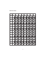
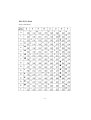
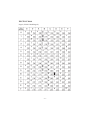
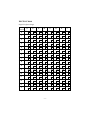
10. CHARACTER CODE TABLES ....................................................... 59
11. AUTOMATIC CUTTER ................................................................... 73
1. OUTLINE
The TSP200 series is ideal for printing text, bar code and graphics.
The TSP200 series has the following features:
1. extremely quiet and fast printing (maximum 50 mm/sec.) using the direct line
thermal printing method
2. support many bar code types
(UPC-A, UPC-E, JAN/EAN-8, JAN/EAN-13, CODE 39, IFT 2 OF 5, CODE
128, CODE 93, NW-7)
3. dual interfaces (RS232C, Parallel)
4. memory switches that enable wide selection of printer default settings
The printer has two different software modes which can be selected using the DIP
switch.
(Factory setting: Star Mode)
Star Mode: DIP switch 1-7 ON
This mode is compatible with Star Receipt printers, such as the SP300 and SP200
series.
ESC/POS Mode: DIP switch 1-7 OFF
This mode is compatible with the printers supporting ESC/POS command.
ESC/POS is a trademark of Seiko Epson Corporation.
For improvement purposes, the descriptions and specifications in this manual are
subject to change without notice.
–1–
2. MEMORY SWITCH AND DIP SWITCH
Functional settings are made using the printer’s EEPROM memory switches and
the DIP switches.
2-1. Memory Switch
Each memory switch is a 16-bit word stored in EEPROM.
The printer is shipped with the factory setting which is made in accordance with
its product type.
For the detailed functions and the settings of the Memory switches, please refer
to “Chapter 8”.
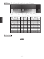
The factory settings are shown in the table below.
Memory switch
#0
#1
#2
#3
#4
TSP212
0000
0000
0000
0000
0000
TSP242
0000
0000
0100
0000
0000
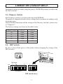
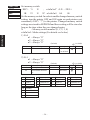
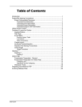
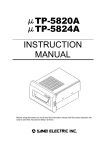
2-2. DIP Switch
Be sure to turn off the power of the printer before changing the setting of the
DIP switches.
Power off
DIP switch
ON
OFF
1
8
DIP switch 1
1
4
DIP switch 2
DIP switch array
–2–
DIP switch #1
The factory settings of DIP switch 1 are all on.
Switch
1-1
1-2
1-3
1-4
1-5
1-6
1-7
1-8
Contents
Baud Rate
ON
Data Length
Parity Check
Parity Selection
Handshake
Operating Mode
Interface
Baud Rate
2400BPS
4800BPS
9600BPS
19200BPS
8 bit
Disabled
Odd
DTR
Star
RS232C
1-1
OFF
ON
ON
OFF
OFF
7 bit
Enabled
Even
XON/XOFF
ESC/POS
Parallel
1-2
OFF
OFF
ON
ON
DIP Switch #2
Factory settings: 2-1 and 2-2 are on; 2-3 and 2-4 are off.
Switch
2-1
2-2
2-3
2-4
Contents
Print Density
ON
Serial I/F No. 6 Pin Reset Signal
Serial I/F No. 8 Pin Reset Signal
Print Density
Light
Standard
Somewhat Heavy
Heavy
2-1
OFF
ON
ON
OFF
Enabled
Enabled
2-2
OFF
ON
OFF
ON
–3–
OFF
Disabled
Disabled
3. DISPLAY PANEL AND FUNCTIONS
3-1. LED
LED
POWER
ON LINE
Function
Lights up when the printer is turned on.
Blinks when an error occurs (Refer to 7. ERRORS.)
Lights up when the printer is on line; goes off when the printer
is off line or error occurs (Refer to 7. ERRORS.)
3-2. Switches
Switch
ON LINE
FEED
Function
Switches between on line and off line
Feeds the paper while pressed
3-3. Switch Operation (Combined Switch Operation)
1) <SELF PRINTING>
FEED + POWER ON (Turn the power on while holding the FEED switch
depressed.)
Self-printing will be performed. VER. NO., Memory switch settings, DIP
switch settings and character order will be printed out.
2) <Hexadecimal dump mode>
ON LINE + POWER ON (Turn the power on while holding the ON LINE
switch depressed.)
Each of the signals sent from the computer to the printer will be printed out
in hexadecimal code.
This function allows you to check if a control code sent to the printer by the
program being used is correct or not. The last line is not printed if its data is
less than one full line. However, if the ON LINE switch is pressed to set the
off line mode, the last line will be printed. To turn off the mode, it is necessary
to turn off the printer completely.
–4–
4. SERIAL INTERFACE
SERIAL
4-1. Interface Specifications
Transmission type ................. Asynchronous serial interface
Baud rate (bps) ..................... 2400, 4800, 9600, or 19200
(Selected by DIP switch)
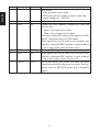
Word format
Start bit: ......................1
Data bits: ....................7 or 8 (Selected by DIP switch)
Parity: ......................... Odd, Even, or None
(Selected by DIP switch)
Stop bit: ......................1
Signal polarities
RS-232C ..................... Mark = Logic “1” (–3V to –15V)
Space = Logic “0” (+3V to +15V)
Handshaking ......................... DTR or XON/XOFF mode (Selected by DIP
switch)
Mark [1]
b0
Space [0]
A
b1
b2
b3
b4
B
b5
b6
(b7)
C
D
A: Start bit
B: Data bits
C: Vertical parity bit
D: Stop bit
–5–
4-2. Interface Circuit
4-2-1. RS-232C Interface
SERIAL
Input (RXD, DSR)
Printer
Host computer
Output (DTR, FAULT, TXD, RTS)
Printer
Host computer
75188 or equivalent
–6–
4-3. Connectors and Signal Names
1
SERIAL
5
6
9
4-3-1. RS-232C Interface
Pin No.
1
2
3
4
Signal name
FG
RXD
TXD
DTR
Direction
–
IN
OUT
OUT
Function
Frame ground
Receiving data
Transmission data
ESC/POS mode
1) DTR/DSR communication mode
Indicates if printer is busy or not.
Space: Printer ready
Mark: Printer busy
The conditions for busy will vary according to
the memory switch settings.
Printer Status
Memory SW #4-4
1
0
1. From when the power BUSY
is turned on or I/F reset
until communication
possible
BUSY
2. Test printing
–––
3. Cover open
4. Paper feed by paper feed – – –
switch
–––
5. Stop due to no paper
6. During waiting for – – –
switch input in macro
execution
–––
7. Other errors
BUSY
8. Receiving buffer full
BUSY
BUSY
BUSY
BUSY
BUSY
BUSY
BUSY
BUSY
2) XON/XOFF Communication mode
Indicates when printer can receive data from
host. This is space, except for the following.
1. After reset until communication possible.
2. During test printing.
–7–
Pin No. Signal name Direction
SERIAL
5
6
SG
DSR
—
IN
7
8
RTS
INIT
OUT
IN
9
FAULT
OUT
Function
Star mode
Data terminal ready signal.
When the printer is ready to receive data, this
signal changes to “SPACE”.
Signal ground
Signal line that indicates whether the host can
receive data
Space : Host can receive data
Mark : Host cannot receive data
Does not confirm the status of this signal in XON/
XOFF communication or STAR mode.
This signal line can be used as an external reset
signal by setting the DIP switches. A pulse width of
1 ms or more mark state activates reset.
Same as DTR signal.
This signal line can be used as an external reset
signal by setting the DIP switches. A pulse width of
1 ms or more space state activates reset.
In the Star mode, the printer will enter the mark
state during the following errors: no paper, head up,
cutter error. In ESC/POS mode, this is normally
space.
–8–
Refer to the host computer’s interface specifications for details of how to connect
the interface. The following illustrations show typical connection configurations.
[RS-232C]
Printer side
IBM PC side (25 pin)
F-GND
1
1
F-GND
RXD
2
2
TXD
TXD
3
3
RXD
DTR
4
4
RTS
S-GND
5
5
CTS
DSR
6
6
DSR
RTS
7
7
S-GND
INIT
8
8
DCD
FAULT
9
20
DTR
Printer side
IBM PC side (9 pin)
F-GND
1
1
DCD
RXD
2
2
RXD
TXD
3
3
TXD
DTR
4
4
DTR
S-GND
5
5
S-GND
DSR
6
6
DSR
RTS
7
7
RTS
INIT
8
8
CTS
FAULT
9
–9–
SERIAL
4-4. Interface Connections
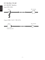
4-5. Data Protocol
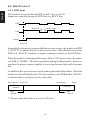
4-5-1. DTR mode
SERIAL
This mode is accessed when the DIP switch 1-6 is set to ON.
Signals are controlled using the DTR line as a BUSY flag.
Data
RXD
Buffer full
Data
Data
Buffer empty
DTR
Printing
Power ON
Immediately after power on (provided that no error occurs), the printer sets DTR
to “SPACE” to indicate that it is ready to receive data. When the host detects that
DTR is in “SPACE” condition, it begins sending text data over the RXD line.
When the printer’s remaining buffer space falls to *256 bytes or less, the printer
sets DTR to “MARK.” The host responds by halting the data transfer. However,
note that the printer remains capable of receiving data until the buffer becomes
full.
Available buffer space increases as the printer prints the buffered data. When the
printer has cleared all but the last *256 bytes of data, it sets DTR back to “SPACE”
to indicate that it is ready to receive more data.
Data buffer full
Nearly full
Nearly empty
*256 bytes
remaining
Empty
*256 bytes
DTR
“MARK”
DTR
“SPACE”
* 16 bytes when the buffer size is set to 45 bytes
– 10 –
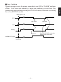
Upon detecting an error, the printer immediately sets DTR to “MARK” and goes
offline. If the error was caused by a paper-out condition, you can clear it by
loading new paper and then pressing the ON LINE switch (Star mode) or closing
the cover (ESC/POS mode).
When paper is out
RXD
OFF LINE
ON LINE
DTR
Printing
Paper out
PAPER OUT signal
Power ON
– 11 –
Press the ON LINE switch after
loading paper (Star mode).
SERIAL
■ Error Condition
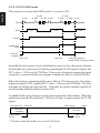
4-5-2. X-ON/X-OFF mode
This mode is accessed when DIP switch 1-6 is set to OFF.
SERIAL
X–OFF
X–OFF
X–OFF X–ON
X–OFF
X–OFF
X–OFF X–ON
X–ON
TXD
RXD
Data
Data
Data
Printing
PAPER OUT
signal
ON
ON LINE
indicator OFF
Power ON
Paper out
Load paper and press
the ON LINE switch (Star mode).
Immediately after power on (provided that no error occurs), the printer informs
the host that it is ready to receive data by outputting the X-ON signal (control code
DC1; value = 11H) over the TXD line. If necessary the printer repeats the signal
every three seconds until the host begins sending text data over the RXD line.
When the printer’s remaining buffer space falls to *256 bytes or less, the printer
begins to output X-OFF signals (DC3, value = 13H) over the TXD line. The host
responds by halting the data transfer. Note that the printer remains capable of
receiving data until the buffer becomes full.
Available buffer space increases as the printer prints the buffered data. When the
printer has cleared all but the last *256 bytes of data, it again outputs the X-ON
signal.
Data buffer full
Nearly full
Nearly empty
*256 bytes
remaining
Empty
*256 bytes
Pinter outputs
X-ON.
Printer outputs
X-OFF.
* 16 bytes when the buffer size is set to 45 bytes
– 12 –
5. PARALLEL INTERFACE
Interface:
Data transfer speed:
Synchronization:
Handshaking:
Logic level:
Conforms with Centronics parallel interface standard
1000 ~ 5000 CPS
External strobe pulse
Using ACK and BUSY
TTL-level compatible
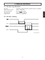
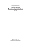
5-2. Interface Timing
ACK
Approx. 9ms
DATA
STROBE
T
BUSY
T
T
T: At least 0.5ms
– 13 –
PARALLEL
5-1. Interface Specifications
Signal Name
Sample Circuit
4.7kW
DATA 1
~
74LS-equivalent
Input
DATA 8
1kW
PARALLEL
100W
STROBE
74LS-equivalent
1000pF
Output
1.8kW
BUSY
ACK
74LS-equivalent
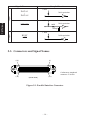
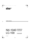
5-3. Connectors and Signal Names
(18)
(1)
Conforms to Amphenol
connector 57-30360
(36)
(19)
(Printer Side)
Figure 5-1. Parallel Interface Connector
– 14 –
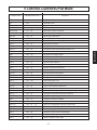
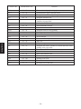
Signal name
STROBE
Direction
IN
2-9
DATA 1~8
IN
10
ACK
OUT
11
BUSY
OUT
12
PAPER OUT
OUT
13
SELECTED
OUT
14-15
16
17
18
19-30
N/C
SIGNAL GND
CHASSIS GND
+5V
TWISTED
PAIR RETURN
31
RESET
IN
32
ERROR
OUT
33
34-35
36
EXT GND
N/C
–
–
Function
Strobe pulse for data read. Usually HIGH;
goes LOW to trigger data read.
Parallel data lines for eight-bit data. HIGH
is “1”; LOW is “0”.
Printer outputs this pulse for approximately 9µs to indicate that data read is
completed. Printer becomes ready to
receive new data at the moment the ACK
pulse ends.
DC-level signal indicating printer’s current status. LOW indicates that printer is
ready to receive the next data; HIGH
indicates that printer is unable to receive.
DC-level signal indicating whether printer
has paper. The signal stays LOW while paper
is present; it goes HIGH to indicate that paper
has run out.
DC-level signal; stays HIGH while printer is
online.
Not used
Signal ground
Printer-frame ground
Outputs +5V (Max. 50mA)
Return pins for various signals. Each pin is
connected to the corresponding signal line by
twisted pair line.
LOW level causes printer to reset its control
circuitry and return to its initial state.
Goes LOW to indicate that printer is unable to
print.
Ground terminal for external connection
Not used
Fixed “HIGH” at printer side
– 15 –
PARALLEL
Pin no
1
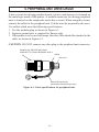
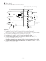
6. PERIPHERAL UNIT DRIVE CIRCUIT
A drive circuit for driving peripheral units (such as cash drawers) is featured on
the main logic board of this printer. A modular connector for driving peripheral
units is featured on the output side on the drive circuit. When using this circuit,
connect the cable for the peripheral unit. (Cables must be prepared by the user.)
Use cables which meet the following specifications.
1. Use the modular plug as shown in Figure 6-1.
2. Separate ground wire is required for Europe only.
3. If the printer is to be used in Europe, the noise filter should be attached to the
cable, as shown in Figure 6-2.
CAUTION: DO NOT connect any other plug to the peripheral unit connector.
Modular plug MOLEX 90075-0007,
AMP641337 or JAPAN BURNDY B-66-4
Shield
1
6
Wire lead
Separated Ground wire
connected to shield (Europe only).
Figure 6-1. Cable specifications for peripheral unit.
– 16 –
Fastener
One loop
Ferrite core
Screw M3×4
Separate ground wire
Peripheral unit drive
circuit connector
Figure 6-2. Separate ground wire and noise filter are required for Europe.
– 17 –
■ Drive circuit
The recommended drive circuit is shown.
[Drive output 24V, max. 1.0 A]
1
F.G
With shield
2
TR1
M-GND
D1
+24V
7824
L1
3
4
D2
TR2
Peripheral
unit 1
L2
R3
4.7kΩ
1/4W
5
M-GND
Peripheral
unit 2
+5V
R1
TR3
Compulsion
switch
6
R2
Frame
ground
NOTES:
1. Peripheral units #1 and #2 cannot be driven simultaneously.
When driving a device continuously, do not use drive duty above 20%.
2. Compulsion switch status is available as status data.
3. Resistance for coils L1 and L2 is not less than 24 ohms.
4. Absolute maximum ratings for diodes D1 and D2 (at Ta=25˚C):
Average rectified current Io = 1A
Maximum forward surge current (60Hz,1-cycle sine wave) IFSM=40A
5. Absolute maximum rating for transistors TR1 and TR2 (at Ta = 25˚C):
Collector current Ic = 2A
– 18 –
7. ERRORS
The various types of errors can be identified by the buzzer’s sound and the lit
LEDs.
Buzzer: The circled numbers refer to “7-4. Type of buzzer sound”.
7-1. Automatic Recovery (Power Lamp: Flashing; On-Line
Lamp: On)
Error Description
Abnormal head
temperature
Power Lamp Flashing Pattern
Approx. 1 Sec
Recovery Conditions
Automatic recovery after head
temperature lowers
Approx. 1 Sec
7-2. Recoverable Errors (Power Lamp: Flashing; On-Line
Lamp: Off)
upper: Star mode
Error Description
lower: ESC/POS mode
Recovery Conditions
Power Lamp Flashing Pattern
No paper
Approx. 1 Sec
Approx. 1 Sec
2
Insert paper and press on-line
switch.
Insert paper and close cover.
Head up
Approx. 250 ms
Approx. 250 ms
3
Lower head and press on-line
switch.
Lower head and close cover.
Paper near end of
roll
Approx. 2 Sec
Approx. 2 Sec
4
Press on-line switch and printing
will continue. Both lamps light
when printing and power lamp
flashes and on-line lamp lights
when on line.
Same as no paper
Cover is open
5
Approx. Approx.
500 ms 500 ms
Close cover and press on-line
switch.
Close cover.
Error during paper
cutting
Approx. 125 ms
Approx. 125 ms
6
If the blade is at the home position,
press the on-line switch for printing
to continue. If the blade is not at the
home position, it is not a recoverable error.
Command
– 19 –
7-3. Fatal Error (Power Lamp: Flashing; On-Line Lamp:
Flashing)
The unit will have to be repaired.
7-4. Type of buzzer sound (only Star mode) P: 50ms Pi: 100ms
1 Online, Offline
2 No Paper
3 Head Up
4 Near End
5 Cover Open
6 Cutter Error
7 Buzzer by command
P
PPPP PPPP
PiPiPi
PP PP
PPPP
Pi PPP PPiPiP PPPPPi PiPiPiPiPi PiPiPiPiPi
Pi
– 20 –
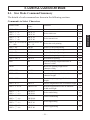
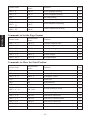
8. CONTROL CODES/STAR MODE
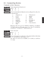
8-1. Star Mode Command Summary
The details of each command are shown in the following sections.
Commands to Select Characters
Control codes
Hexadecimal
codes
Function
<ESC> “R” n
1B 52 n
Select international character set
25
<ESC> “/” “1”
<ESC> “/” <1>
1B 2F 31
1B 2F 01
Select slash zero
25
<ESC> “/” “0”
<ESC> “/” <0>
1B 2F 30
1B 2F 00
Select normal zero
25
<ESC> “b” n1 n2 n3 n4 1B 62 n1 n2 n3 n4
d1 ... <RS>
d1 ... 1E
Select bar code printing
26
<ESC> “M”
1B 4D
Select 12-dot pitch printing
30
<ESC> “p”
1B 70
Select 14-dot pitch printing
30
<ESC> “P”
1B 50
Select 15-dot pitch printing
30
<ESC> “:”
1B 3A
Select 16-dot pitch printing
30
<ESC> <SP> n
1B 20 n
Set character spacing
30
<SO>
0E
Sets the printing magnified double in
character width.
31
<DC4>
14
Resets the printing magnified in
character width.
31
<ESC> “W” n
1B 57 n
Sets the magnification rate in character width. 31
<ESC> <SO>
1B 0E
Sets the printing magnified double in
character height.
31
<ESC> <DC4>
1B 14
Resets the printing magnified in character
height.
31
<ESC> “h” n
1B 68 n
Sets the magnification rate in character height.
32
<ESC> “i” n1 n2
1B 69 n1 n2
Sets the magnification rates in character
width and height.
32
<ESC> “–” “1”
<ESC> “–” <1>
<ESC>“–” “0”
<ESC> “–” <0>
1B 2D 31
1B 2D 01
Select underlining
32
1B 2D 30
1B 2D 00
Cancel underlining
32
<ESC> “_” “1”
<ESC> “_” <1>
1B 5F 31
1B 5F 01
Select upperlining
33
<ESC> “_” “0”
<ESC> “_” <0>
1B 5F 30
1B 5F 00
Cancel upperlining
33
– 21 –
STAR MODE
Page
Control codes
Hexadecimal
codes
Function
<ESC> “4”
1B 34
Select highlight printing
33
<ESC> “5”
1B 35
Cancel highlight printing
33
<SI>
0F
Inverted printing
33
<DC2>
12
Cancel inverted printing
33
<ESC> “E ”
<ESC> “G ”
1B 45
1B 47
Select emphasized printing
34
<ESC> “F ”
<ESC> “H ”
1B 46
1B 48
Cancel emphasized printing
34
Page
STAR MODE
Commands to Set the Page Format
Control codes
Hexadecimal
codes
Function
<ESC> “C” n
1B 43 n
Set page length in lines
<ESC> “C” <0> n
1B 43 00 n
Set page length in inches
35
<ESC> “N” n
1B 4E n
Set bottom margin
35
<ESC> “O”
1B 4F
Cancel bottom margin
35
<ESC> “l” n
1B 6C n
Set left margin
36
<ESC> “Q” n
1B 51 n
Set right margin
36
Page
35
Commands to Move the Print Position
Control codes
Hexadecimal
codes
Function
Page
<LF>
0A
Line feed
37
<CR>
0D
Carriage Return
37
<ESC> “a” n
1B 61 n
Feed paper n lines
37
<FF>
0C
Form feed
37
<HT>
09
Horizontal tab
37
<VT>
0B
Vertical tab
38
<ESC> “z” “1”
<ESC> “z” <1>
1B 7A 31
1B 7A 01
Set line spacing to 4 mm
38
<ESC> “0”
1B 30
Set line spacing to 3 mm
38
<ESC> “J” n
1B 4A n
One time n/4 mm feed
38
<ESC> “j” n
1B 6A n
One time n/4 mm backfeed
39
<ESC>“I” n
1B 49 n
One time n/8 mm feed
39
<ESC> “B” n1 n2 ... <0> 1B 42 n1 n2 ... 00
Set vertical tab stops
39
<ESC> “D” n1 n2 ... <0> 1B 44 n1 n2 ... 00
Set horizontal tab stops
40
– 22 –
Commands to Print Dot Graphics
Control codes
Hexadecimal
codes
Function
<ESC> “K” n <0>
m1 m2 ...
1B 4B n 00 m1 m2
...
Print normal density graphics
<ESC> “L” n1 n2
m1 m2 ...
<ESC> “k” n <0> d1 ...
1B 4C n1 n2 m1 m2
Print high density graphics
...
1B 6B n 00 d1 ...
Print fine density graphics
<ESC> “X” n1 n2 m1 ... 1B 58 n1 n2 d1 ...
Print fine density graphics
Page
41
43
44
47
Control codes
Hexadecimal
codes
<ESC> “&” <1> <1>
n m1 m2 ... m48
1B 26 01 01 n
m1 m2 ... m48
<ESC> “&” “1” “1”
n m1 m2 ... m48
1B 26 31 31 n
m1 m2 ... m48
<ESC> “&” <1> <0> n
1B 26 01 00 n
<ESC> “&” “1” “0” n
1B 26 31 30 n
<ESC> “%” “1”
<ESC> “%” <1>
<ESC> “%” “0”
<ESC> “%” <0>
Function
Page
Define download character
48
Delete a download character
49
1B 25 31
1B 25 01
Enable download character set
49
1B 25 30
1B 25 00
Disable download character set
50
Commands to Control Peripheral Devices
Control codes
Hexadecimal
codes
<ESC> <BEL> n1 n2
1B 07 n1 n2
Define drive pulse width for peripheral
device #1
51
<BEL>
07
Control peripheral device #1
51
<FS>
1C
Control peripheral device #1 immediately
51
<EM>
19
Control peripheral device #2 immediately
51
<SUB>
1A
Control peripheral device #2 immediately
51
Function
Page
Commands to Control Auto Cutter
Control codes
Hexadecimal
codes
Function
<ESC> “d” “0”
<ESC> “d” <0>
1B 64 30
1B 64 00
Full-cut command to the auto cutter
52
<ESC> “d” “1”
<ESC> “d” <1>
1B 64 31
1B 64 01
Partial-cut command to the auto cutter
52
– 23 –
Page
STAR MODE
Commands to Print Download Characters
Other Commands
Control codes
Hexadecimal
codes
Function
<CAN>
18
Cancel last line & Initialize printer
53
<DC3>
13
Deselect printer
53
<DC1>
<RS>
11
1E
Set select mode
Beep the buzzer
53
53
<ESC> “#N, n1 n2 n3 n4” 1B 23 N 2C n1 n2 n3 n4
Set memory switch
<LF> <NUL>
0A 00
<ESC> “@”
1B 40
Initialize printer
<ENQ>
05
STAR MODE
<ESC> “?” <LF> <NUL> 1B 3F 0A 00
Page
54
55
Enquiry
55
Reset printer hardware
56
– 24 –
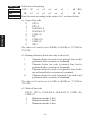
8-2. Command Specification
Commands to Select Characters
FUNCTION
Select international character set
CODE
<ESC> “R”
REMARKS
1B
52
n
Selects an international character set according to the value of n,
as shown below:
n
0
1
2
3
4
5
6
Character set
U.S.A.
France
Germany
England
Denmark I
Sweden
Italy
n
7
8
9
10
11
12
Character set
Spain I
Japan
Norway
Denmark II
Spain II
Latin America
When the value of n is 0 to 9, 0(00H) to 9(09H) or “0”(30H) to
“9”(39H) can be set. When the value of n is 10 to 12, 10(0AH) to
12(0CH) or “A”(41H) to “C”(43H) can be set.
FUNCTION
Select zero style
CODE
<ESC> “/”
HEX
REMARKS
1B
2F
n
n
Causes subsequent zero characters to be printed with a slash when
n is 1, and without a slash when n is 0.
The value of n can be set to 0(00H) or “0”(30H), or 1(01H) or
“1”(31H).
– 25 –
STAR MODE
HEX
n
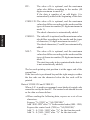
FUNCTION
Select bar code printing
CODE
<ESC> “b”
HEX
REMARKS
1B
62
n1
n2
n3
n4
di
...
dk <RS>
n1
n2
n3
n4
di
...
dk
1E
Prints bar code according to the value of n1, as shown below:
n1: Type of bar code
STAR MODE
0
1
2
3
4
5
6
7
8
UPC-E
UPC-A
JAN/EAN-8
JAN/EAN-13
CODE 39
ITF
CODE 128
CODE 93
NW-7
The value of n1 can be set to 0(00H) or 8(08H) or “0”(30H) to
“8”(38H).
n2: Printing character below bar code or line feed
1
2
3
4
Character below bar code is not printed, Line feed is
performed after execution of command.
Character below bar code is printed, Line feed is
performed after execution of command.
Character below bar code is not printed, Line feed is
not performed after execution of command.
Character below bar code is printed, Line feed is not
performed after execution of command.
The value of n2 can be set to 1(01H) to 4(04H) or “1”(31H) to
“4”(34H).
n3: Mode of bar code
UPC-E, UPC-A, JAN/EAN-8, JAN/EAN-13, CODE 128,
CODE 93
1
Minimum module 2 dots
2
Minimum module 3 dots
3
Minimum module 4 dots
– 26 –
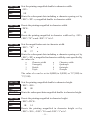
CODE 39, NW-7, ITF
Narrow : wide
Narrow : wide
Narrow : wide
Narrow : wide
Narrow : wide
Narrow : wide
Narrow : wide
Narrow : wide
Narrow : wide
CODE 39, NW-7
2:6 dots
3:9 dots
4:12 dots
2:5 dots
3:8 dots
4:10 dots
2:4 dots
3:6 dots
4:8 dots
ITF
2:5 dots
4:10 dots
6:15 dots
2:4 dots
4:8 dots
6:12 dots
2:6 dots
3:9 dots
4:12 dots
When the value of n3 is UPC-E, UPC-A, JAN/EAN-8, JAN/EAN13, CODE128 or CODE93, 1(01H) to 3(03H) or “1”(31H) to
“3”(33H) can be set. When the value of n3 is CODE39, NW-7 or
ITF, 1(01H) to 9(09H) or “1”(31H) to “9”(39H) can be set.
n4: Height of bar code
Can be up to 255 dots (31.9mm).
If the bar code height is larger than the line feed amount, the
line feed amount is automatically multiplied by an integer.
di...dk: Bar code data
UPC-E/UPC-A: K = 11 (or 12)
The check digit at the 12th digit is automatically added,
and ignored even if it is specified.
JAN/EAN-8: K = 7 (or 8)
The check digit at the 8th digit is automatically added,
and ignored even if it is specified.
JAN/EAN-13: K = 12 (or 13)
The check digit at the 13th digit is automatically added,
and ignored even if it is specified.
CODE39: The value of k is optional, and the maximum
value also differs according to the modes (21
digits maximum in mode 7).
The start/stop code (“* ”) is automatically added.
– 27 –
STAR MODE
1
2
3
4
5
6
7
8
9
ITF:
The value of k is optional, and the maximum
value also differs according to the modes (40
digits maximum in mode 4).
If the data is number of an odd digits, 0 is
automatically added at the beginning of the data.
CODE 128: The value of k is optional, and the maximum
value also differs according to the modes and the
types of character number (51 digits maximum in
mode 1).
The check character is automatically added.
STAR MODE
CODE93: The value of k is optional, and the maximum value
also differs according to the modes and the types
of character (30 digits maximum in mode 1).
The check characters (C and K) are automatically
added.
NW-7:
The value of k is optional, and the maximum
value also differs according to the modes and the
types of character number (29 digits maximum in
mode 7).
The start/stop code is also contained in the data (it
is not automatically added).
The bar code printing start position is at the upper end of the
current line.
If the bar code is positioned beyond the right margin, neither
the bar code nor the character below the bar code will be
printed.
Data of CODE 128 and CODE 93
When <LF> is used in a command, some kinds of control code
cannot be sent by the host PC. The control code should be sent
as the data as shown below:
• When sending the following data, express as a set of two
characters.
Express “% (25H)” as “%0 (25H30H)”.
Add “40H - 5FH” after “%” for the control codes (00H - 1FH).
Express the control code (7FH) as “%5(25H35H)”.
Add “1 - 4 (31H - 34H)” after “%” for the function code.
Add “6 - 8 (36H - 38H)” after “%” for the start code.
– 28 –
3) 2-character codes
Special code
CODE
NUL 00H
SOH 01H
STX 02H
ETX 03H
EOT 04H
ENQ 05H
ACK 06H
BEL 07H
BS
08H
HT
09H
LF
0AH
VT
0BH
FF
0CH
CR
0DH
SO
0EH
SI
0FH
DLE 10H
DC1 11H
DC2 12H
DC3 13H
DC4 14H
FORMAT
%@ 25H 40H
%A 25H 41H
%B 25H 42H
%C 25H 43H
%D 25H 44H
%E 25H 45H
%F 25H 46H
%G 25H 47H
%H 25H 48H
%I 25H 49H
%J 25H 4AH
%K 25H 4BH
%L 25H 4CH
%M 25H 4DH
%N 25H 4EH
%O 25H 4FH
%P 25H 50H
%Q 25H 51H
%R 25H 52H
%S 25H 53H
%T 25H 54H
NAK
SYN
ETB
CAN
EM
SUB
ESC
FC
GS
RS
US
DEL
%U
%V
%W
%X
%Y
%Z
%[
%¥
%]
%^
%_
%5
15H
16H
17H
18H
19H
1AH
1BH
1CH
1DH
1EH
1FH
7FH
25H
25H
25H
25H
25H
25H
25H
25H
25H
25H
25H
25H
– 29 –
55H
56H
57H
58H
59H
5AH
5BH
5CH
5DH
5EH
5FH
35H
%
CODE
25H
FORMAT
%0 25H 30H
Function codes
CODE
FNC1
FNC2
FNC3
FNC4
FORMAT
%1 25H 31H
%2 25H 32H
%3 25H 33H
%4 25H 34H
✩
✩
✩
✩
FORMAT
%6 25H 36H
%7 25H 37H
%8 25H 38H
✩
✩
✩
Start codes
CODE
START A
START B
START C
✩ For CODE 128 only.
STAR MODE
Control codes
FUNCTION
Select 12-dot pitch printing
CODE
<ESC> “M”
HEX
1B
4D
REMARKS
Prints 12-dot pitch characters without an extra space.
FUNCTION
Select 14-dot pitch printing
CODE
<ESC> “p”
HEX
1B
70
STAR MODE
REMARKS
Prints 12-dot pitch characters with 2-dot spacing between characters.
FUNCTION
Select 15-dot pitch printing
CODE
<ESC> “P”
HEX
1B
50
REMARKS
Prints 12-dot pitch characters with 3-dot spacing between characters.
FUNCTION
Select 16-dot pitch printing
CODE
<ESC> “:”
HEX
1B
3A
REMARKS
Prints 12-dot pitch characters with 4-dot spacing between characters.
FUNCTION
Set the character spacing
CODE
<ESC> <SP>
HEX
REMARKS
1B
20
n
n
Sets the space between characters to n dots, where n is a number
from 0 to 15.
When the value of n is 0 to 9, 0(00H) to 9(09H) or “0”(30H) to
“9”(39H) can be set. When the value of n is 10 to 15, 10(0AH) to
15(0FH) or “A”(41H) to “F”(46H) can be set.
– 30 –
FUNCTION
Sets the printing magnified double in character width.
CODE
<SO>
0E
REMARKS
Prints the subsequent data including a character spacing set by
<ESC><SP> n, magnified double in character width.
FUNCTION
Resets the printing magnified in character width.
CODE
<DC4>
HEX
14
REMARKS
Resets the printing magnified in character width set by <SO>,
<ESC>“W”n and <ESC>“i”n1n2.
FUNCTION
Sets the magnification rate in character width.
CODE
<ESC> “W”
HEX
REMARKS
1B
57
n
n
Prints the subsequent data including a character spacing set by
<ESC><SP> n, magnified in character width by a rate specified by
the value of n.
n
0
1
2
Character width
Unmagnify
Double
Triple
n
3
4
5
Character width
Quadruple
Quintuple
Sextuple
The value of n can be set to 0(00H) to 5(05H) or “0”(30H) to
“5”(35H).
FUNCTION
Sets the printing magnified double in character height.
CODE
<ESC> <SO>
HEX
1B
0E
REMARKS
Prints the subsequent data magnified double in character height.
FUNCTION
Resets the printing magnified in character height.
CODE
<ESC><DC4>
HEX
REMARKS
1B
14
Resets the printing magnified in character height set by
<ESC><SO>, <ESC>“h”n and <ESC>“i”n1n2.
– 31 –
STAR MODE
HEX
FUNCTION
Sets the magnification rate in character height.
CODE
<ESC> “h”
HEX
REMARKS
1B
68
n
n
Prints the subsequent data magnified in character height by a rate
specified by the value of n.
n
0
1
2
Character height
Unmagnify
Double
Triple
n
3
4
5
Character height
Quadruple
Quintuple
Sextuple
STAR MODE
The value of n can be set to 0(00H) to 5(05H) or “0”(30H) to
“5”(35H).
FUNCTION
Sets the magnification rates in character width and height.
CODE
<ESC> “i” n1 n2
HEX
REMARKS
1B
69 n1 n2
Prints the subsequent data in the size specified by n1, n2.
n1 indicates the height magnification and n2 indicates the width
magnification.
n1 (n2) = 0 Normal height (or width) size.
1 Double height (or width) size.
2 Triple height (or width) size.
3 Quadruple height (or width) size.
4 Quintuple height (or width) size.
5 Sextuple height (or width) size.
The values of n1, n2 are 0(00H) to 5(05H) or “0”(30H)” to
“5”(35H).
FUNCTION
Underlining
CODE
<ESC> “–”
HEX
REMARKS
1B
2D
n
n
When the value of n is 1, underlines the subsequent data including
a character spacing set by <ESC><SP> n.
The part to be skipped by the horizontal tab setting and the block
graphic characters are not underlined.
Resets the underline mode when the value of n is 0.
The value of n can be set to 0(00H) or “0”(30H), or 1(01H) or
“1”(31H).
– 32 –
Upperlining
CODE
<ESC> “_”
HEX
1B
5F
n
n
REMARKS
When the value of n is 1, overlines the subsequent data including
a character spacing set by <ESC><SP> n.
The part to be skipped by the horizontal tab setting and the block
graphic characters are not upperlined.
Resets the upperline mode when the value of n is 0.
The value of n can be set to 0(00H) or “0”(30H), or 1(01H) or
“1”(31H).
FUNCTION
Select highlight printing
CODE
<ESC> “4”
HEX
1B
34
REMARKS
Prints the subsequent data including a character spacing set by
<ESC><SP> n reversed.
The part to be skipped by the horizontal tab setting is not reversed.
FUNCTION
Cancel highlight printing
CODE
<ESC> “5”
HEX
1B
35
REMARKS
Cancels highlight printing.
FUNCTION
Inverted printing
CODE
HEX
<SI>
0F
REMARKS
Causes subsequent characters to be inverted.
FUNCTION
Cancel inverted printing
CODE
<DC2>
HEX
REMARKS
12
Cancels inverted printing.
– 33 –
STAR MODE
FUNCTION
FUNCTION
Select emphasized printing
CODE
<ESC> “E”
HEX
CODE
HEX
1B
45
<ESC> “G”
1B
47
REMARKS
Causes subsequent characters to be emphasized.
FUNCTION
Cancel emphasized printing
CODE
<ESC> “F”
STAR MODE
HEX
CODE
HEX
REMARKS
1B
46
<ESC> “H”
1B
48
Cancels emphasized printing.
– 34 –
Commands to Set the Page Format
FUNCTION
Set page length in lines
CODE
<ESC> “C”
1B
43
n
REMARKS
Sets the page length using the current line spacing, where n is
between 1 and 127.
Changing the line spacing later does not alter the physical page
length.
The current line becomes the top of the page.
Resets the bottom margin.
Default page length is 42 lines.
FUNCTION
Set page length in inches
CODE
<ESC> “C” <0>
HEX
REMARKS
1B
43
00
n
Sets the page length to n × 24 mm, where n is between 1 and 22.
The current line becomes the top of the page.
Resets the bottom margin.
FUNCTION
Set bottom margin
CODE
<ESC> “N”
HEX
n
1B
4E
n
n
REMARKS
Sets the bottom margin to n lines at the current line spacing, where
n is between 0 and 127.
Bottom margin is reset when you change the page length.
Setting is invalid if the printing area on one page is 36 mm or less.
FUNCTION
Cancel bottom margin
CODE
<ESC> “O”
HEX
REMARKS
1B
4F
Cancels the bottom margin.
– 35 –
STAR MODE
HEX
n
FUNCTION
Set left margin
CODE
<ESC> “l”
HEX
1B
6C
n
n
STAR MODE
REMARKS
Sets the left margin at column n (where n is between 0 and 255) at
the current character pitch.
The left margin does not move if the character pitch is changed
later.
Setting is invalid if the printing area for one line would be 36mm
or less.
FUNCTION
Set right margin
CODE
<ESC> “Q”
HEX
REMARKS
1B
51
n
n
Sets the right margin at column n (where n is between 1 and 255)
at the current character pitch.
The right margin does not move if the character pitch is changed
later.
Setting is invalid if column n is beyond the right edge of the
printing area.
Setting is invalid if the printing area for one line would be 36mm
or less.
– 36 –
Commands to Move the Print Position
CODE
HEX
Line feed
<LF>
0A
REMARKS
Prints the current line and feeds the paper to the next line.
FUNCTION
Carriage return
CODE
<CR>
HEX
0D
REMARKS
Prints the current line and feeds the paper to the next line.
This command is ignored when CR code is invalid.
FUNCTION
Feed paper n lines
CODE
<ESC> “a”
HEX
1B
61
n
n
REMARKS
Prints the current line and feeds the paper n lines (where n is
between 1 and 127).
FUNCTION
Form feed
CODE
HEX
<FF>
0C
REMARKS
Feeds the paper to the top of the next page, according to the page
length set by <ESC>“C”n or <ESC>“C”<0>n when memory switch
1-2 is set to 0. If memory switch 1-2 is set to 1, the paper is fed 18 mm,
cut fully, and then feed back 18 mm. The print position is at the left
margin in both cases.
FUNCTION
Horizontal tab
CODE
<HT>
HEX
REMARKS
09
Moves the print position to the next horizontal tab stop. Ignored if
there is no next horizontal tab stop on the current line.
– 37 –
STAR MODE
FUNCTION
FUNCTION
Vertical tab
CODE
<VT>
HEX
0B
STAR MODE
REMARKS
Prints the current line and feeds the paper to the next vertical tab
stop and moves the print position to the left margin.
Performs paper feed if no vertical tabs are set or if the current line
is at or below the last vertical tab stop.
FUNCTION
Set line spacing to 4 mm
CODE
<ESC> “z”
HEX
1B
7A
“1”
or <ESC> “z”
31
or
1B
<1>
7A
01
REMARKS
Sets the distance the paper advances in subsequent line feeds to
4 mm.
FUNCTION
Set line spacing to 3 mm
CODE
<ESC> “0”
HEX
1B
30
REMARKS
Sets the distance the paper advances in subsequent line feeds to
3 mm.
FUNCTION
One time n/4 mm feed
CODE
<ESC> “J”
HEX
REMARKS
1B
4A
n
n
Performs a line feed of n/4mm once only.
The value of n is 1 to 255.
Space setting for lines is not changed.
– 38 –
FUNCTION
One time n/4 mm backfeed
CODE
<ESC> “j”
1B
6A
n
REMARKS
Feeds the paper back n/4mm once only.
The value of n is 1 to 255.
Space setting for one line is not changed.
This command can also feed the paper back to the page before the
current page. In this case, the position of the line on the previous
page is determined by the page length control.
FUNCTION
One time n/8 mm feed
CODE
<ESC> “I”
HEX
1B
49
n
n
REMARKS
Performs a line feed n/8mm once only.
The value of n is 1 to 255.
Space setting for lines is not changed.
FUNCTION
Set vertical tab stops
CODE
<ESC> “B”
HEX
REMARKS
1B
42
n1
n2
...
<0>
n1
n2
...
00
Cancels all current vertical tab stops and sets new vertical tab stops
at lines n1, n2, etc., where n1, n2, etc. are numbers between 0 and
255. A maximum of 16 vertical tab stops can be set.
The tab stops must be specified in ascending order; any violation
of ascending order terminates the tab stop list. Standard termination is by the <0> control code.
The vertical tab stops are set in terms of the current line spacing and
do not move if the line spacing is changed later.
– 39 –
STAR MODE
HEX
n
FUNCTION
Set horizontal tab stops
CODE
<ESC> “D”
HEX
REMARKS
1B
44
n1
n2
...
<0>
n1
n2
...
00
Cancels all current horizontal tab stops and sets new tab stops at
columns n1, n2, etc. at the current character pitch, where n1, n2,
etc. are numbers between 1 and 255. A maximum of 16 horizontal
tab stops can be set.
The tab stops must be specified in ascending order; any violation
of ascending order terminates the tab stop list. Standard termination is by the <0> control code.
STAR MODE
– 40 –
FUNCTION
Print normal density graphics
CODE
<ESC> “K”
1B
HEX
4B
n
<0>
m1
m2
...
n
00
m1
m2
...
Prints normal density dot graphics. The graphics image is 24 dots
high and n × 3 dots wide. Maximum width is 576 dots.
m1, m2, ... are the dot data, each a 1-byte value from 0 to 255
representing 24 vertical dots, with the most significant bit representing the top three and the least significant bit representing the
bottom three.
The number of data bytes must be n.
Dots beyond the right margin are ignored.
REMARKS
Relationship between image data and print dots
MSB
DOT Position
1
2
D8
Image data
D7
D6
3
1
2
3
4
5
6
7
8
9
10
11
12
13
14
15
16
17
18
19
20
21
22
23
24
– 41 –
D5
LSB
D4
D3
D2
D1
STAR MODE
Commands to Print Dot Graphics
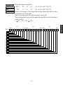
EXAMPLE
We will create the design below using a bit image.
m1 m2 m3 m4 m5
m6 m7 m8 m9 m10 m11 m12 m13 m14 m15 m16 m17 m18 m19 m20 m21 m22 m23 m24 m25 m26 m27 m28 m29 m30
D8
D7
D6
D5
D4
D3
D2
D1
First, since the volume of data is 30, n1 = (1E)H. If the data m1 ~
m30 is converted to hexadecimal, it appears as shown below.
STAR MODE
Data
Binary
Hexadecimal
Data
Binary
Hexadecimal
Data
Binary
Hexadecimal
m1
m2
m3
m4
m5
m6
m7
m8
m9
m10
00000001
00011110
00111110
01011111
00011111
01011110
00011110
00111111
00101111
00111110
01
1E
3E
5F
1F
5E
1E
3F
2F
3E
m11
m12
m13
m14
m15
m16
m17
m18
m19
m20
00111110
00000010
00000010
00111110
00111110
00101111
00101111
00111110
00101110
00101110
3E
02
02
3E
3E
2F
2F
3E
2E
2E
m21
m22
m23
m24
m25
m26
m27
m28
m29
m30
00111110
00101110
00101110
00111110
00101111
00101111
00111110
00111110
00000010
00000010
3E
2E
2E
3E
2F
2F
3E
3E
02
02
Printing Sample
– 42 –
Print high density graphics
CODE
<ESC> “L”
1B
HEX
4C
n1
n2
m1
m2
...
n1
n2
m1
m2
...
Prints high density dot graphics. The graphics image is 24 dots
high and n1 + n2 × 256 dots wide. Maximum width is 576 dots.
m1, m2, ... are the dot data, each a 1-byte value from 0 to 255
representing 24 vertical dots, with the most significant bit representing the top three and the least significant bit representing the
bottom three.
The number of data bytes must be n1 + n2 × 256.
Dots beyond the right margin are ignored.
REMARKS
Relationship between image data and print dots
MSB
DOT Position
D8
Image data
D7
D6
D5
1
1
2
3
4
5
6
7
8
9
10
11
12
13
14
15
16
17
18
19
20
21
22
23
24
– 43 –
LSB
D4
D3
D2
D1
STAR MODE
FUNCTION
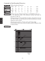
EXAMPLE
We will create the design below using a bit image.
m1 m2 m3 m4 m5
m6 m7 m8 m9 m10 m11 m12 m13 m14 m15 m16 m17 m18 m19 m20 m21 m22 m23 m24 m25 m26 m27 m28 m29 m30
D8
D7
D6
D5
D4
D3
D2
D1
First, since the volume of data is 30, n1 = (1E)H. If the data m1 ~
m30 is converted to hexadecimal, it appears as shown below.
STAR MODE
Data
Binary
Hexadecimal
Data
Binary
Hexadecimal
Data
Binary
Hexadecimal
m1
m2
m3
m4
m5
m6
m7
m8
m9
m10
00000001
00011110
00111110
01011111
00011111
01011110
00011110
00111111
00101111
00111110
01
1E
3E
5F
1F
5E
1E
3F
2F
3E
m11
m12
m13
m14
m15
m16
m17
m18
m19
m20
00111110
00000010
00000010
00111110
00111110
00101111
00101111
00111110
00101110
00101110
3E
02
02
3E
3E
2F
2F
3E
2E
2E
m21
m22
m23
m24
m25
m26
m27
m28
m29
m30
00111110
00101110
00101110
00111110
00101111
00101111
00111110
00111110
00000010
00000010
3E
2E
2E
3E
2F
2F
3E
3E
02
02
Horizontal density is three times that of the bit image for <ESC>“k”.
(Compare the print samples.)
Printing Sample
FUNCTION
Print fine density bit image
CODE
<ESC>
“k”
n
<0>
d1...dk [k = n * 24]
1B
6B
n
00
d1...dk [k = n * 24]
HEX
REMARKS
Prints a bit image using 1 horizontal dot and 1 vertical dot for 1 dot
of input data.
n is designated by the number of data bytes in the horizontal
direction and n must be within the range 1 to 72.
The data is ignored if it is longer than 72 digits or goes beyond the
right margin. Relationship between the input data and actual
printing is shown below.
– 44 –
Relationship between image data and print dots
Image data
b7 b6 b5 b4 b3 b2 b1 b0
Dot position
d2
b1 b0 b7 b6 b5 b4 b3 b2
dn+2
b1 b0 b7 b6 b5 b4 b3 b2
d2n+2
b1 b0 b7 b6 b5 b4 b3 b2
d3n+2
b1 b0 b7 b6 b5 b4 b3 b2
d4n+2
b1 b0 b7 b6 b5 b4 b3 b2
d5n+2
b1 b0 b7 b6 b5 b4 b3 b2
d6n+2
b1 b0 b7 b6 b5 b4 b3 b2
d7n+2
b1 b0 b7 b6 b5 b4 b3 b2
d8n+2
b1 b0 b7 b6 b5 b4 b3 b2
d9n+2
b1 b0 b7 b6 b5 b4 b3 b2
d10n+2
b1 b0 b7 b6 b5 b4 b3 b2
d11n+2
b1 b0 b7 b6 b5 b4 b3 b2
d12n+2
b1 b0 b7 b6 b5 b4 b3 b2
d13n+2
b1 b0 b7 b6 b5 b4 b3 b2
d14n+2
b1 b0 b7 b6 b5 b4 b3 b2
d15n+2
b1 b0 b7 b6 b5 b4 b3 b2
d16n+2
b1 b0 b7 b6 b5 b4 b3 b2
d17n+2
b1 b0 b7 b6 b5 b4 b3 b2
d18n+2
b1 b0 b7 b6 b5 b4 b3 b2
d19n+2
b1 b0 b7 b6 b5 b4 b3 b2
d20n+2
b1 b0 b7 b6 b5 b4 b3 b2
d21n+2
b1 b0 b7 b6 b5 b4 b3 b2
d22n+2
b1 b0 b7 b6 b5 b4 b3 b2
d23n+2
b1 b0 b7 b6 b5 b4 b3 b2
– 45 –
b1 b0
•
•
•
b1 b0
•
•
•
b1 b0
•
•
•
b1 b0
•
•
•
b1 b0
•
•
•
b1 b0
•
•
•
b1 b0
•
•
•
b1 b0
•
•
•
b1 b0
•
•
•
b1 b0
•
•
•
b1 b0
•
•
•
b1 b0
•
•
•
b1 b0
•
•
•
b1 b0
•
•
•
b1 b0
•
•
•
b1 b0
•
•
•
b1 b0
•
•
•
b1 b0
•
•
•
b1 b0
•
•
•
b1 b0
•
•
•
b1 b0
•
•
•
b1 b0
•
•
•
b1 b0
•
•
•
b1 b0
•
•
•
dn
b7 b6 b5 b4 b3
d2n
b7 b6 b5 b4 b3
d3n
b7 b6 b5 b4 b3
d4n
b7 b6 b5 b4 b3
d5n
b7 b6 b5 b4 b3
d6n
b7 b6 b5 b4 b3
d7n
b7 b6 b5 b4 b3
d8n
b7 b6 b5 b4 b3
d9n
b7 b6 b5 b4 b3
d10n
b7 b6 b5 b4 b3
d11n
b7 b6 b5 b4 b3
d12n
b7 b6 b5 b4 b3
d13n
b7 b6 b5 b4 b3
d14n
b7 b6 b5 b4 b3
d15n
b7 b6 b5 b4 b3
d16n
b7 b6 b5 b4 b3
d17n
b7 b6 b5 b4 b3
d18n
b7 b6 b5 b4 b3
d19n
b7 b6 b5 b4 b3
d20n
b7 b6 b5 b4 b3
d21n
b7 b6 b5 b4 b3
d22n
b7 b6 b5 b4 b3
d23n
b7 b6 b5 b4 b3
d24n
b7 b6 b5 b4 b3
b2 b1 b0
b2 b1 b0
b2 b1 b0
b2 b1 b0
b2 b1 b0
b2 b1 b0
b2 b1 b0
b2 b1 b0
b2 b1 b0
b2 b1 b0
b2 b1 b0
b2 b1 b0
b2 b1 b0
b2 b1 b0
b2 b1 b0
b2 b1 b0
b2 b1 b0
b2 b1 b0
b2 b1 b0
b2 b1 b0
b2 b1 b0
b2 b1 b0
b2 b1 b0
b2 b1 b0
STAR MODE
d1
b7 b6 b5 b4 b3 b2
dn+1
b7 b6 b5 b4 b3 b2
d2n+1
b7 b6 b5 b4 b3 b2
d3n+1
b7 b6 b5 b4 b3 b2
d4n+1
b7 b6 b5 b4 b3 b2
d5n+1
b7 b6 b5 b4 b3 b2
d6n+1
b7 b6 b5 b4 b3 b2
d7n+1
b7 b6 b5 b4 b3 b2
d8n+1
b7 b6 b5 b4 b3 b2
d9n+1
b7 b6 b5 b4 b3 b2
d10n+1
b7 b6 b5 b4 b3 b2
d11n+1
b7 b6 b5 b4 b3 b2
d12n+1
b7 b6 b5 b4 b3 b2
d13n+1
b7 b6 b5 b4 b3 b2
d14n+1
b7 b6 b5 b4 b3 b2
d15n+1
b7 b6 b5 b4 b3 b2
d16n+1
b7 b6 b5 b4 b3 b2
d17n+1
b7 b6 b5 b4 b3 b2
d18n+1
b7 b6 b5 b4 b3 b2
d19n+1
b7 b6 b5 b4 b3 b2
d20n+1
b7 b6 b5 b4 b3 b2
d21n+1
b7 b6 b5 b4 b3 b2
d22n+1
b7 b6 b5 b4 b3 b2
d23n+1
b7 b6 b5 b4 b3 b2
EXAMPLE
MSB
Printing Sample
LSB
MSB
LSB
STAR MODE
d1
d3
d5
d7
d9
d11
d13
d15
d17
d19
d21
d23
d25
d27
d29
d31
d33
d35
d37
d39
d41
d43
d45
d47
d2
d4
d6
d8
d10
d12
d14
d16
d18
d20
d22
d24
d26
d28
d30
d32
d34
d36
d38
d40
d42
d44
d46
d48
Data
Binary
Hexadecimal
Data
Binary
Hexadecimal
d1
d3
d5
d7
d9
d11
d13
d15
d17
d19
d21
d23
d25
d27
d29
d31
d33
d35
d37
d39
d41
d43
d45
d47
00000000
00011111
00111111
01110111
11111000
11111000
11111000
00001111
00011111
00011111
00111110
00111000
011111001
01110011
01110011
11111001
11111000
11111110
11111111
11111111
00000000
00000000
00000000
00000000
00
1F
3F
77
F8
F8
F8
0F
1F
1F
3E
38
79
73
73
F9
F8
FE
FF
FF
00
00
00
00
d2
d4
d6
d8
d10
d12
d14
d16
d18
d20
d22
d24
d26
d28
d30
d32
d34
d36
d38
d40
d42
d44
d46
d48
00000000
11111000
11111100
01110111
00011111
00011111
00011111
11110000
11111000
11111000
01111100
00011100
10011110
11001110
11001110
10011111
00011111
01111111
11111111
11111111
00000000
00000000
00000000
00000000
00
F8
FC
EE
1F
1F
1F
F0
F8
F8
7C
1C
9E
CE
CE
9F
1F
7F
FF
FF
00
00
00
00
– 46 –
FUNCTION
Print fine density graphics
CODE
<ESC>
“X”
n1
n2
d1...d [(n1+n2*256)*3]
1B
5
n1
n2
d1...d [(n1+n2*256)*3]
REMARKS
Prints a bit image of the input data using horizontal and vertical
resolutions of 8 dots/mm.
Data extending past the right margin is ignored.
The relationship between the input data and the actual printing is
shown below.
576
1 n1 + n2 × 256
d1•••
MSB
LSB
Dot
Position b7 b6 b5 b4 b3 b2 b1 b0
d2•••
MSB
d3•••
LSB
b7 b6 b5 b4 b3 b2 b1 b0
1
2
3
4
5
6
7
8
9
10
11
12
13
14
15
16
17
18
19
20
21
22
23
24
– 47 –
MSB
LSB
b7 b6 b5 b4 b3 b2 b1 b0
STAR MODE
HEX
Commands to Print Download Characters
FUNCTION
Define download character
CODE
<ESC> “&” <1> <1>
HEX
CODE
HEX
REMARKS
1B
26
<ESC> “&”
1B
26
n
m1
m2
...
m48
01
01
n
m1
m2
...
m48
“1”
“1”
n
m1
m2
...
m48
31
31
n
m1
m2
...
m48
STAR MODE
Defines one new character and stores it in RAM for later use.
n is the character code of the character defined and must be
between 32 and 127.
If the maximum of 32 external characters have already been stored,
the oldest stored external character are deleted so that new external
character can be stored.
The character matrix is 12 dots wide and 24 dots high.
Relationship between the character pattern and the character data
is shown below.
EXAMPLE
MSB
LSB
MSB
LSB
m1
m3
m5
m7
m9
m11
m13
m15
m17
m19
m21
m23
m25
m27
m29
m31
m33
m35
m37
m39
m41
m43
m45
m47
m2
m4
m6
m8
m10
m12
m14
m16
m18
m20
m22
m24
m26
m28
m30
m32
m34
m36
m38
m40
m42
m44
m46
m48
Ignored
4 bits
– 48 –
Binary
Hexadecimal
Data
Binary
Hexadecimal
m1
m3
m5
m7
m9
m11
m13
m15
m17
m19
m21
m23
m25
m27
m29
m31
m33
m35
m37
m39
m41
m43
m45
m47
00011000
00111000
01111000
00011000
00011000
00011000
00011000
00011001
00011011
00000110
00001100
00011011
00110111
01100110
00000000
00000000
00000001
00000011
00000111
00000111
00000000
00000000
00000000
00000000
18
38
78
18
18
18
18
19
1B
06
0C
1B
37
66
00
00
01
03
07
07
00
00
00
00
m2
m4
m6
m8
m10
m12
m14
m16
m18
m20
m22
m24
m26
m28
m30
m32
m34
m36
m38
m40
m42
m44
m46
m48
00000000
00000000
00000000
00000000
00000000
01100000
11000000
10000000
00000000
00000000
00000000
11000000
11100000
01100000
01100000
11000000
10000000
00000000
11100000
11100000
00000000
00000000
00000000
00000000
00
00
00
00
00
60
C0
80
00
00
00
C0
E0
60
60
C0
80
00
E0
E0
00
00
00
00
FUNCTION
Delete a download character
CODE
<ESC> “&” <1> <0>
HEX
CODE
HEX
1B
26
<ESC> “&”
1B
26
n
01
00
n
“1”
“0”
n
31
30
n
REMARKS
Deletes the download character which was assigned the value n.
FUNCTION
Enable download character set
CODE
<ESC> “%”
HEX
REMARKS
1B
25
“1”
or <ESC> “%” <1>
31
or
1B
25
Enables the download character set.
– 49 –
01
STAR MODE
Data
FUNCTION
Disable download character set
CODE
<ESC> “%”
HEX
REMARKS
1B
25
“0”
or <ESC> “%” <0>
30
or
1B
25
00
Disables the selected download character set and returns to the
built-in ROM character set.
STAR MODE
– 50 –
Commands to Control Peripheral Devices
FUNCTION
Define drive pulse width for peripheral device #1
CODE
<ESC><BEL> n1
1B
07
n1
n2
REMARKS
Defines the drive pulse width for peripheral devices requiring
other than standard 200 ms pulse time and delay time.
n1 indicates the energizing time and n2 indicates the delay time,
using 10ms units.
FUNCTION
Control peripheral device #1
CODE
<BEL>
HEX
07
REMARKS
Executes drive pulse for peripheral device #1.
FUNCTION
Control peripheral device #1 immediately
CODE
<FS>
HEX
1C
REMARKS
Executes drive pulse for peripheral device #1 immediately.
FUNCTION
Control peripheral device #2 immediately
CODE
<EM>
HEX
19
REMARKS
Drives peripheral device #2. The drive pulse width and delay time
are fixed at 200 ms.
FUNCTION
Control peripheral device #2 immediately
CODE
<SUB>
HEX
REMARKS
1A
Drives peripheral device #2. The drive pulse width and delay time
are fixed at 200 ms.
– 51 –
STAR MODE
HEX
n2
Commands to Control Auto Cutter
FUNCTION
Full-cut command to the auto cutter
CODE
<ESC> “d”
HEX
1B
64
“0”
or <ESC> “d”
30
or
1B
64
<0>
00
STAR MODE
REMARKS
Cuts the paper fully when memory switch 2-C is set to 0. If memory
switch 2-C is set to 1, the paper is fed to 18 mm and cut fully.
When auto cutter is invalid, this command is not valid.
FUNCTION
Partial-cut command to the auto cutter
CODE
<ESC> “d”
HEX
REMARKS
1B
64
“1”
or <ESC> “d”
31
or
1B
64
<1>
01
Cuts the paper partially when memory switch 2-C is set to 0. If
memory switch 2-C is set to 1, the paper is fed to 18 mm and cut
partially.
– 52 –
Other Commands
FUNCTION
Cancel last line & Initialize printer
CODE
<CAN>
18
REMARKS
Clears the line buffer, and initializes the commands set already.
Does not affect the external equipment drive conditions set by the
code <ESC> <BEL> n1 n2. (This is the same during a mechanical
error.)
(Line buffer means the print data expansion area.)
FUNCTION
Deselect printer
CODE
<DC3>
HEX
13
REMARKS
Deselects the printer. The printer disregards all subsequent characters and commands except <DC1>, which activates the printer.
FUNCTION
Set select mode
CODE
<DC1>
HEX
(11)H
REMARKS
When the printer receives a <DC1> code, the deselect mode is
canceled and data following this code is input to the buffer.
FUNCTION
Beep the buzzer
CODE
<RS>
HEX
REMARKS
1E
Sounds a brief beep tone.
– 53 –
STAR MODE
HEX
FUNCTION
Set memory switch
CODE
<ESC> “#
HEX
REMARKS
1B
23
N
, n1n2n3n4” <LF> <NUL>
N
2C n1n2n3n4
0A
00
STAR MODE
Set the memory switch. In order to enable changed memory switch
setting, turn the printer OFF and ON again or send printer reset
command (<ESC> “?”) to the printer. Changed memory switch
settings are stored in EEPROM and these setting will be stored as
long as the time when they are changed again.
N
:Memory switch number (0, 1, 2, 3, 4)
n1n2n3n4 :Mode settings (For details see below)
1) N=0
n1 :Always “0”
n2 :Always “0”
n3 :Always “0”
(Default)
: Available
Parameter
n4
Setting
FF command
0
Form Feed
4
Paper Feed,
Cut & Back
Star
ESC/POS
–
2) N=1
n1 :Always “0”
n2 :Always “0”
Parameter
n3
n4
Setting
Zero style
International character
set
n4
0
1
2
Country
USA
France
Germany
n4
C
Country
Latin America
n4
3
4
5
Country
UK
Denmark #1
Sweden
– 54 –
(Default)
0
1
Normal zero Slashed zero
See below
n4
6
7
8
Country
Italy
Spain #1
Japan
n4
9
A
B
Star
: Available
ESC/POS
–
–
Country
Norway
Denmark #2
Spain #2
3) N=2
n3 :Always “0”
Parameter
n1
Setting
ESC d command
n2
Cutter
n4
Paper near end
(Default)
0
Cut
Invalid
(TSP212)
Invalid
1
Paper feed
& cut
Valid
(TSP242)
Valid
Star
: Available
ESC/POS
–
–
n1 :Always “0”(Default)
Parameter
n2
n3
n4
Setting
0
Character table Normal
Print column
48
CR code
Invalid
1
IBM
38
Invalid
Line feed (mm) 4
3
2
Katakana
–
Same as
<LF>
4
: Available
3
Star ESC/POS
IBM
–
–
–
Same as
<LF>
–
3
5) N=4
n1 :Always “0”
Parameter
n2
n3
n4
Setting
Buffer size
Busy conditions
Data receive error
FUNCTION
Initialize printer
CODE
<ESC> “@”
HEX
1B
(Default)
0
1
4 Kbytes
45 bytes
See 4-3-1 RS-232C Interface
Print “?”
Ignore
Star
: Available
ESC/POS
–
–
40
REMARKS
Reinitializes the printer. Clears the print buffer and returns settings
to their power-up values.
Does not clear the input buffer, downloaded characters, or conditions for peripheral devices.
FUNCTION
Enquiry
CODE
<ENQ>
HEX
REMARKS
05
Causes the printer to transmit a status byte.
– 55 –
STAR MODE
4) N=3
Status byte
b7
b6
b5
b4
b3
b2
b1
b0
0
Constantly
set at “0”
Vertical Parity error
1 : error
Framing error
1 : error
Mechanical error
1 : error
STAR MODE
Paper empty
1 : empty
Buffer empty
1 : empty
Buffer overflow
1 : overflow
Compulsion switch
High level
(Switch is set to ON)
FUNCTION
Reset the printer hardware.
CODE
<ESC> “?” <LF><NUL>
HEX
REMARKS
1B
3F
0A
00
Resets the printer hardware.
– 56 –
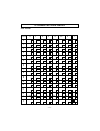
9. CONTROL CODES/ESC/POS MODE
Hexadecimal Code
Function
HT
LF
FF
DLE EOT
DLE ENQ
CAN
ESC FF
ESC SP
ESC !
ESC #
ESC $
ESC %
ESC &
ESC
ESC ESC 2
ESC 3
ESC =
ESC ?
ESC @
ESC D
09
0A
0C
10
10
18
1B
1B
1B
1B
1B
1B
1B
1B
1B
1B
1B
1B
1B
1B
1B
FF
20
21
23
24
25
26
2A
2D
32
33
3D
3F
40
44
Horizontal tab
Print line feed
Page mode print and return
Real time transmission of status
Real time request to printer
Cancel print data in page mode
Print page mode data
Set right space amount of character
Universal print mode designation
Set memory switch
Designate absolute printing
Designate/cancel download character set
Define download characters
Designate bit image mode
Designate/cancel underline
Set 1/6 inch line feed amount
Set line feed amount
Select peripheral equipment
Delete download characters
Initialize printer
Set horizontal tab position
ESC E
ESC G
ESC J
ESC L
ESC R
ESC S
ESC T
ESC V
ESC W
ESC \
ESC a
ESC c4
ESC c5
ESC d
ESC i
ESC p
ESC t
1B
1B
1B
1B
1B
1B
1B
1B
1B
1B
1B
1B
1B
1B
1B
1B
1B
45
47
4A
4C
52
53
54
56
57
5C
61
63
63
64
69
70
74
Designate/cancel emphasized print
Designate/cancel double print
Print and paper feed
Select page mode
Select international characters
Select standard mode
Select character print direction in print mode
Designate/cancel 90° character rotation
Set print range in page mode
Designate relative position
Align position
Select no valid paper detector at print stop
Enable/disable panel switch
Print and paper feed “n” lines
Partial cut (one section remaining)
Designate pulse generation
Select character code table
*
04
05
34
35
– 57 –
ESC/POS
Control Code
Control Code
Hexadecimal Code
ESC/POS
ESC u
ESC v
ESC {
GS !
GS $
1B
1B
1B
1D
1D
75
76
7B
21
24
GS
GS /
GS :
GS B
GS H
GS I
GS L
GS P
GS V
GS W
GS \
*
1D
1D
1D
1D
1D
1D
1D
1D
1D
1D
1D
2A
2F
3A
42
48
49
4C
50
56
57
5C
GS ^
GS a
GS f
GS h
GS k
GS r
GS w
1D
1D
1D
1D
1D
1D
1D
5E
61
66
68
6B
72
77
Function
Transmission of peripheral equipment status
Transmission of paper detection status
Designate/cancel inverted printing
Designate character size
Designate absolute position of vertical direction of
characters in page mode
Define download bit image
Print download bit image
Start/finish macro definition
Designate/cancel reverse printing
Select print position of HRI characters
Printer ID transmission
Set left margin
Set basic calculated pitch
Paper cut
Set print range
Designate the relative position of vertical characters when
printing in the page mode
Execute macro
Enable/disable automatic status transmission
Select HRI character font
Set bar code height
Printing of bar code
Transmission of status
Set lateral size of bar code
– 58 –
10. CHARACTER CODE TABLES
Star Mode
Hexadecimal
0
0
1
0
2
2
<DC3>
3
4
4
B
C
D
E
F
#
35
$
4
21
6
22
37
&
7
23
<CAN>
8
<HT>
<SUB>
10
<VT>
<ESC>
14
+
<
M
>
N
62
?
47
– 59 –
124
}
109
n
94
_
79
|
m
^
123
108
93
78
O
63
l
]
122
{
107
92
77
z
k
\
121
106
91
76
61
46
/
31
L
=
j
[
120
y
105
90
75
60
45
30
K
x
i
Z
119
104
89
74
59
44
.
<RS>
J
;
h
Y
118
w
103
88
73
58
43
29
<SI>
15
:
–
13
I
v
g
X
117
102
87
72
57
42
28
<CR>
<SO>
*
,
<FS>
12
9
41
27
H
56
f
W
116
u
101
86
71
t
e
V
115
100
85
70
G
8
40
26
11
<FF>
(
25
F
55
d
U
114
s
99
84
69
54
7
)
<EM>
9
<LF>
6
39
24
E
r
c
T
113
98
83
68
53
38
’
<BEL>
D
5
b
S
112
q
97
82
67
52
a
R
C
p
96
81
66
51
36
Q
B
7
`
80
65
50
3
%
5
A
2
6
P
64
49
34
20
<ENQ>
8
A
1
”
5
@
48
33
19
<DC4>
6
9
!
18
4
0
32
17
<DC2>
3
7
16
<DC1>
1
3
SP
<NUL>
1
5
2
125
~
110
126
111
127
o
95
Star Mode
(Character table: Normal)
Hexadecimal
8
9
A
128
144
1
129
145
146
è
3
131
147
ß
132
148
5
133
149
6
134
150
7
135
151
165
ì
167
183
A
153
138
154
B
139
155
C
140
156
170
142
158
F
143
159
174
243
212
228
244
213
229
245
214
230
246
215
231
247
216
232
248
217
233
249
218
234
250
219
235
251
220
236
252
221
237
253
222
238
254
223
239
255
±
ä
205
÷
á
190
ú
175
227
∞
204
189
ü
ë
203
θ
ô
A
E
202
188
173
211
X
o
/4
157
242
TL
Å
187
172
226
x
201
186
171
¥
141
i
ò
1
D
200
185
ó
T
X
210
σ
ö
N
T
241
∑
199
184
169
225
µ
198
î
/2
137
197
E
168
209
Ω
n
182
¢
152
196
181
240
°F
N
166
1
9
180
f
136
195
¿
í
224
°C
ç
ï
164
ª
º
194
179
208
°
û
ê
163
§
193
178
F
â
u
e
E
a
192
177
162
D
ù
176
161
Ü
130
8
160
Ö
2
C
é
Ä
0
4
B
206
π
à
191
– 60 –
207
Star Mode
(Character table: katakana)
– 61 –
Star Mode
(Character table: IBM)
Hexadecimal
0
1
2
3
4
5
6
7
8
9
A
B
C
8
A
É
Ç
128
ü
145
Æ
130
â
147
ö
132
148
133
134
ç
150
ù
135
ê
151
ÿ
136
ë
è
177
193
209
ª
º
162
178
194
210
163
179
195
211
180
196
165
181
197
213
166
182
198
214
167
183
199
215
243
228
244
229
245
÷
230
τ
153
169
185
201
217
246
≈
231
Φ
216
247
°
232
248
Θ
233
Ω
170
186
202
218
171
187
203
234
219
172
188
204
220
236
173
158
189
205
221
237
253
238
254
239
255
∈
174
190
206
222
∩
»
159
252
2
«
ƒ
251
∩
i
157
250
235
∞
/4
156
249
–
δ
1
Pt
143
≤
227
µ
200
¥
Å
242
σ
184
£
142
226
212
/2
141
241
≥
∑
168
155
140
±
π
1
î
240
225
Γ
152
154
139
≡
224
β
Ü
138
E
161
¿
ï
Ä
208
Ö
137
Ì
192
Ñ
û
å
176
164
149
F
α
160
ñ
ò
à
E
ú
ô
ä
D
ó
146
131
C
í
æ
é
B
á
144
129
D
F
9
175
191
– 62 –
207
223
Star Mode
International Character Set
35 36 64 91 92 93 94 96 123 124 125 126
]
ˆ
`
{
}
~
° ç §
ˆ
`
é ù è
¨
Germany
# $ § Ä Ö Ü
ˆ
`
England
£ $ @ [
]
ˆ
`
ä ö ü ß
{ | } ~
Denmark 1
# $ @ Æ Ø Å
ˆ
` æ ø å ~
Sweden
# ¤ É Ä Ö Å Ü é ä ö å ü
Italy
# $ @ °
U. S. A.
# $ @ [
France
# $ à
Spain 1
\
\
\
|
é
ˆ
ù à ò è
$ @ ¡ Ñ ¿
ˆ
’
¨
ñ
}
ì
~
ˆ
`
{
|
}
~
Japan
# $ @ [
¥
Norway
# ¤ É Æ Ø Å Ü é æ ø å ü
Denmark 2
# $ É Æ Ø Å Ü é æ ø å ü
Spain 2
# $ á
¡ Ñ ¿ é
’
í
ñ ó ú
Latin America
# $ á
¡ Ñ ¿ é ü
í
ñ ó ú
– 63 –
]
ESC/POS Mode
Hexadecimal
0
1
0
1
<NUL> <DLE>
0
<XON>
3
3
<XOFF>
4
20
%
<ENQ>
5
21
7
7
23
B
C
D
5
<CAN>
8
38
9
(
8
26
<ESC>
11
9
+
28
;
44
29
14
30
F
15
31
M
61
>
46
/
N
?
47
O
63
– 64 –
m
^
94
}
125
~
110
o
95
124
109
n
_
79
123
|
108
93
78
{
l
]
122
107
92
77
62
k
\
121
z
106
91
76
y
j
[
120
105
90
75
L
=
45
.
E
K
60
i
Z
119
x
104
89
74
59
<
–
<GS>
J
w
h
Y
118
103
88
73
58
43
,
12
I
:
g
X
117
v
102
87
72
57
42
27
<FF>
56
41
*
10
H
u
f
W
116
101
86
71
115
t
e
V
G
s
100
85
70
55
40
25
<LF>
13
7
)
<HT>
F
114
99
d
U
113
r
c
84
69
54
39
24
E
53
6
’
68
q
98
83
T
112
97
b
S
D
52
37
&
22
A
4
a
82
67
p
96
81
R
C
51
36
Q
66
7
`
80
65
B
3
35
$
<EOT>
A
50
6
P
64
49
2
#
19
6
9
1
34
5
@
48
33
18
6
8
!
17
4
0
32
”
2
5
3
SP
16
1
2
4
2
126
SP
111
127
ESC/POS Mode
Page 0 (PC437: USA, Standard Europe)
Hexadecimal
0
1
2
3
4
5
6
7
8
9
A
B
C
D
E
F
8
9
Ç
A
ü
144
145
Æ
é
130
â
147
ö
132
ò
à
133
134
ç
150
ù
135
ê
151
ÿ
136
ë
192
208
161
177
193
209
ª
º
è
162
178
194
210
163
179
195
211
164
180
196
212
165
181
197
213
166
182
198
214
167
183
199
215
200
216
153
169
185
201
217
170
186
202
218
171
187
203
219
245
÷
230
246
≈
231
247
°
232
248
•
233
172
234
188
204
220
173
158
189
205
236
221
252
237
253
∈
174
190
206
222
238
∩
»
159
251
n
2
«
ƒ
250
235
i
157
249
.
∞
/4
Pt
143
229
δ
1
¥
Å
244
Ω
¬
156
142
228
Θ
£
Ä
243
Φ
184
155
141
≤
227
τ
/2
Ì
242
µ
168
ï
140
226
σ
1
î
241
≥
∑
152
154
139
±
225
π
¿
Ü
138
240
Γ
Ö
137
≡
224
β
Ñ
149
û
å
176
ñ
148
F
α
160
ú
ô
ä
E
ó
146
131
D
í
æ
129
C
á
É
128
B
175
191
– 65 –
207
223
254
SP
239
255
ESC/POS Mode
Page 1(Katakana)
– 66 –
ESC/POS Mode
Page 2 (PC850: Multilingual)
– 67 –
ESC/POS Mode
Page 3 (PC860: Portuguese)
Hexadecimal
0
1
2
3
4
5
6
7
8
9
A
8
9
Ç
A
ü
144
é
145
â
146
147
õ
ã
132
ò
à
133
134
ç
150
ù
135
192
208
161
177
193
209
151
ê
ª
º
Ê
152
Õ
137
162
178
194
210
163
179
195
211
è
164
180
196
212
165
181
197
213
166
182
198
214
167
183
199
215
C
D
Ì
184
200
E
Ã
185
201
F
186
202
218
171
187
203
219
159
247
°
232
248
•
233
249
.
234
250
235
∞
188
204
220
251
n
236
252
2
173
189
205
221
237
253
∈
174
190
206
222
238
∩
»
Ó
143
≈
δ
«
158
246
231
i
Pt
Â
230
217
170
172
157
245
÷
Θ
/4
Ù
142
244
229
216
1
156
141
228
Φ
169
155
140
243
Ω
£
Ô
≤
227
τ
/2
139
242
µ
1
B
226
σ
Ò
154
241
≥
∑
Ü
138
±
225
π
168
153
240
Γ
¿
136
≡
224
β
Ñ
149
Ú
Á
176
ñ
148
F
α
160
ú
ô
131
E
ó
È
130
D
í
À
129
C
á
É
128
B
175
191
– 68 –
207
223
254
SP
239
255
ESC/POS Mode
Page 4 (PC863: Canadian-French)
– 69 –
ESC/POS Mode
Page 5 (PC865: Nordic)
Hexadecimal
0
1
2
3
4
5
6
7
8
9
A
B
C
8
Ç
ü
145
Æ
130
â
147
ö
132
148
133
134
ç
150
ù
135
ê
151
ÿ
136
ë
è
161
177
193
209
ª
º
138
î
162
178
194
210
163
179
195
211
180
196
165
181
197
213
166
182
198
214
≤
227
243
228
244
229
245
167
183
199
215
µ
÷
230
246
τ
≈
231
Φ
216
153
169
185
201
217
247
°
232
248
Θ
•
233
Ω
170
186
202
218
/2
171
187
203
219
172
188
204
220
234
250
235
251
∞
1
/4
156
n
236
173
189
205
221
158
174
190
206
222
175
191
207
223
253
238
254
∩
¤
159
237
∈
«
ƒ
252
2
i
157
249
.
δ
1
Pt
143
242
σ
200
Ø
Å
226
212
184
£
142
241
≥
∑
168
155
141
±
225
π
152
154
140
240
Γ
¿
ø
139
≡
224
β
Ü
ï
E
208
Ö
137
Ä
192
Ñ
û
å
176
164
149
F
α
160
ñ
ò
à
E
ú
ô
ä
D
ó
146
131
C
í
æ
é
B
á
144
129
Ì
A
É
128
D
F
9
– 70 –
SP
239
255
ESC/POS Mode
Page 255 (Space Page)
Hexadecimal
0
1
2
3
4
5
6
7
8
9
A
B
C
D
E
F
8
9
SP
A
SP
128
SP
SP
144
SP
129
SP
SP
SP
SP
SP
131
SP
SP
SP
SP
SP
133
SP
SP
SP
SP
SP
SP
SP
SP
SP
SP
SP
SP
SP
SP
SP
SP
SP
SP
SP
SP
SP
SP
SP
143
174
SP
SP
SP
175
SP
191
– 71 –
SP
SP
222
SP
253
SP
238
SP
223
252
237
SP
SP
207
251
SP
236
221
206
SP
SP
SP
250
235
220
205
190
SP
SP
249
SP
234
219
204
189
SP
SP
159
SP
SP
SP
SP
248
233
218
203
188
173
158
SP
SP
SP
SP
247
SP
232
217
202
187
172
157
142
SP
SP
SP
141
SP
SP
SP
SP
246
231
216
201
186
171
156
SP
SP
SP
SP
245
SP
230
215
200
185
170
155
140
SP
SP
SP
139
SP
SP
SP
SP
244
229
214
199
184
169
154
SP
SP
SP
SP
243
SP
228
213
198
183
168
153
138
SP
SP
SP
137
SP
SP
SP
SP
242
227
212
197
182
167
152
SP
SP
SP
SP
241
SP
226
211
196
181
166
151
136
SP
SP
SP
SP
SP
SP
SP
240
225
210
195
180
165
150
135
SP
SP
SP
SP
SP
224
209
194
179
164
149
134
SP
SP
SP
SP
F
SP
208
193
178
163
148
SP
SP
E
SP
192
177
162
147
132
SP
SP
D
SP
176
161
146
C
SP
160
145
130
B
254
SP
239
255
ESC/POS Mode
International Character Set
35 36 64 91 92 93 94 96 123 124 125 126
\
]
ˆ
`
{
}
~
° ç
§
ˆ
`
é ù è
¨
Germany
# $ § Ä Ö Ü ˆ
`
England
£ $ @ [
]
ˆ
`
ä ö ü ß
{ | } ~
Denmark 1
# $ @ Æ Ø Å
ˆ
` æ ø å ~
Sweden
# ¤ É Ä Ö Å Ü é ä ö å ü
Italy
# $ @ °
é
ˆ
ù à ò è
Spain
Pt $ @ ¡ Ñ ¿
ˆ
’
¨
ñ
}
ì
~
Japan
# $ @ [
ˆ
`
{
|
}
~
Norway
# ¤ É Æ Ø Å Ü é æ ø å ü
Denmark 2
# $ É Æ Ø Å Ü é æ ø å ü
U. S. A.
# $ @ [
France
# $ à
\
\
¥
– 72 –
]
|
11. AUTOMATIC CUTTER
The TSP242 comes equipped with a guillotine-type automatic paper cutter.
1 The cutter operates in response to data commands. To enable cutter operation,
set Memory Switch #2-8 to indicate that the cutter is installed.
2 NEVER place fingers or metal objects in the cutter area.
3 If a jam occurs in the cutter area, switch off the power, use tweezers to remove
the jammed paper, then switch the power back on. The printer will return the
blade to the home position.
4 Never clean the cutter blade with alcohol or any other solvent, as this may
remove the blade’s lubrication and shorten the blade life.
– 73 –
MEMO
P1996.11
OVERSEAS SUBSIDIARY COMPANIES
STAR MICRONICS AMERICA, INC.
70-D Ethel Road West, Piscataway, NJ 08854 U.S.A
Tel: 908-572-9512, Fax: 908-572-5095
STAR MICRONICS DEUTSCHLAND GMBH
Westerbachstraße 59, D-60489 Frankfurt, Germany
Tel: 069-789990, Fax: 069-781006
ELECTRONIC PRODUCTS DIVISION
STAR MICRONICS CO., LTD.
STAR MICRONICS U.K. LTD.
Star House, Peregrine Business Park, Gomm Road,
536 Nanatsushinnya, Shimizu, Shizuoka, 424 Japan High Wycombe, Bucks, HP13 7DL, U.K.
Tel: 0543-47-0112, Fax: 0543-48-5271
Tel: 01494-471111, Fax: 01494-473333
Printed in Japan, 80872025