1
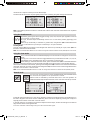
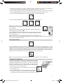
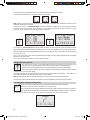
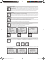
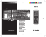
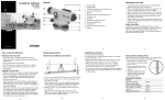
UL 633
Spectra
Precision
Division
Trimble Construction
Trimble
Trimble
Division
Construction
Construction
Division
Division
8261
Route
235
5475 State
Kellenburger
5475
Road
5475
Kellenburger
Kellenburger
RoadRoad
Dayton, Ohio 45424-6383
45424
Dayton,
Dayton,
Ohio Ohio
4542445424
U.S.A.
USA
USA USA
UL
633
GL400 Series
GL400
GL400
Series
Series
User Guide
User Guide
User Guide
Bedienungsanleitung
Bedienungsanleitung
Bedienungsanleitung
Manuel de l´utilisateur
Manuel
Manuel
de l´utilisateur
de l´utilisateur
Guida per l´uso GuidaGuida
per l´uso
per l´uso
Gúia del usuario Gúia del
Gúia
usuario
del usuario
Gebruikershandleiding
Gebruikershandleiding
Gebruikershandleiding
OperatörshandbokOperatörshandbok
Operatörshandbok
Brugermanual Brugermanual
Brugermanual
Guia do Usuário Guia do
Guia
Usuário
do Usuário
Bruksanvisning Bruksanvisning
Bruksanvisning
Käyttäjän opas Käyttäjän
Käyttäjän
opas opas
Instrukcja obsługi
Руководство
пользователя
取扱説明書
取扱説明書
取扱説明書
+1-937-245-5010
Phone
+1-937-245-5600
+1-937-245-5600
+1-937-245-5600
Phone
Phone
©2012
2007,, Trimble Navigation Limited.
© 2007,
All rights
Trimble
© 2007,
reserved.
Navigation
Trimble Navigation
Limited. AllLimited.
rights reserved.
All rights reserved.
©
www.trimble.com
www.trimble.com
www.trimble.com
www.trimble.com
www.trimble.com
www.trimble.com
PN Q104735 Rev. A(01/12)
111560trimble_UL633_00_Um.indd 1
19.01.12 12:45
f
d
Service and Customer Advice
North-Latin America
c
Trimble Spectra Precision Division
8261 State Route 235
Dayton, Ohio 45424
U.S.A.
+1 (888) 272-2433
(Toll Free in U.S.A.)
+1-937-482-0030 Fax
www.trimble.com
www.spectraprecision.com
www.spectra-productivity.com
e
b
Africa & Middle East
Trimble Export Middle-East
P.O. Box 17760
JAFZ View, Dubai
UAE
+971-4-881-3005 Phone
+971-4-881-3007 Fax
h
i
a
Europe
Trimble Kaiserslautern GmbH
Am Sportplatz 5
67661 Kaiserslautern
GERMANY
+49-6301-711414 Phone
+49-6301-32213 Fax
g
Asia-Pacific
Trimble Navigation Singapore PTE Ltd.
80 Marine Parade Road, #22-06
Parkway Parade
Singapore, 449269
+65 6348 2212 Phone
+65 6348 2232 Fax
l
China
Trimble Beijing
Room 2805-07, Tengda Plaza,
No. 168 Xiwai Street
Haidian District
Beijing, China 100044
+86 10 8857 7575 Phone
+86 10 8857 7161 Fax
www.trimble.com.cn
i
j
k
Printed in Germany
111560trimble_UL633_00_Um.indd 2
Q104735 Rev. A(01/12)
19.01.12 12:46
TABLE OF CONTENTS
Introduction
FOR YOUR SAFETY
COMPONENTS
How to use the Laser System
Powering the Laser
RC603 Radio/IR Remote Control
Turning On/Off the RC603
LASER SETUP
Turning On/Off the Laser
Features and functions
Standard Features
X-Y-Z-grade entering mode
Using the Rotation mode
Using the Scan mode
Manual mode
Special MENU Features
Menu Functions (Radio controlled)
Menu Functions (IR controlled)
Automatic PlaneLok mode
Automatic Grade Match
Manual Grade Match
Automatic Axis Alignment
Manual Spot Search mode
Activating/Deactivating Standby mode
Start Reference Check
Centering the Rotor
Setting Menu
Info
Service menu
Special Features - Vertical Setup
Z-Axis Automatic Spot Align
Z-axis Automatic Spot Lok
Z-axis Automatic Spot Match
Line Scan
Beam Plunge
Setting menu details
Pairing
Pairing the transmitter with remote control
Pairing the transmitter with receiver
Mask mode
Grade Entry
Grade Display
Sensitivity
HI-alert selection
User Name
Set Password
Password On/Off
Radio RF-Channel)
CALIBRATION
Checking Calibration of the Y- and X-Axes
Checking Calibration of the Z-(vertical) Axis
Troubleshooting
SF601 Spot Finder User Guide
PROTECTING THE UNIT
CLEANING AND MAINTENANCE
PROTECTING THE ENVIRONMENT
WARRANTY
TECHNICAL DATA
GB
2
2
2
3
3
3
3
4
4
4
5
5
6
6
6
7
7
7
8
8
9
9
10
10
11
11
11
11
11
12
12
13
13
14
14
14
14
15
15
15
16
16
16
16
17
17
17
17
18
18
18
19
20
23
23
23
23
24
1
111560trimble_UL633_01_GB.indd 1
19.01.12 13:24
Introduction
Thank you for choosing one of the Spectra Precision Lasers from the Trimble family of precision lasers.
The universal laser is an easy-to-use tool that offers accurate horizontal, vertical and sloped laser reference
up to 1300 ft (400 m) away using a receiver. The plumb beam can be detected automatically and manually
using the additional SpotFinder
For Your Safety
For hazardless and safe operation, read all the user guide instructions.
LASER RADIATION
AVOID DIRECT EYE
EXPOSURE CLASS 3A/3R
LASER PODUCT
• Use of this product by people other than those trained on this product may result in exposure to hazardous
laser light.
• Do not remove warning labels from the unit.
• The UL633 is Class 3A/3R (< 5mW, 600 ... 680 nm).
• Never look into the laser beam or direct it to the eyes of other people.
• Always operate the unit in a way that prevents the beam from getting into people‘s eyes.
• If initial service is required, which results in the removal of the outer protective cover, removal must only be
performed by factory-trained personnel.
Caution: Use of other than the described user and calibration tools or other procedures may result
in exposure to hazardous laser light.
Caution: Using different than described at the UL633 user guide, may result in unsafe operation.
COMPONENTS
aKeypad/LCD-Display
bHandle
c Rotor with fan beam lens
dSunshade
eAxes-Alignment-Marks
f Sighting Guides/Scope Mounts
g Battery door
h Rubber Cover/Recharge Jack
i 5/8” x 11 Tripod Mounts
j Rubber Feet
k Turnable Legs
l Plus and Minus Battery Diagrams
2
111560trimble_UL633_01_GB.indd 2
19.01.12 13:24
HOW TO USE THE LASER SYSTEM
POWERING THE LASER
Batteries
WARNING
Ni-MH batteries may contain small amounts of harmful substances. Be sure to charge the battery
before using it for the first time, and after not using it for an extended length of time. Charge only with
specified chargers according to device manufacturer‘s instructions. Do not open the battery, dispose
of in fire or short circuit; it may ignite, explode, leak or get hot causing personal injury. Dispose in
accordance with all applicable federal, state, and local regulations. Keep the battery away from
children. If swallowed, do not induce vomiting. Seek medical attention immediately
Recharging the Batteries
The laser is shipped with a rechargeable Ni-MH battery pack.
Note: The approximate charge of the batteries is shown at the left top side of the LCD.
The charger requires approx. 10 hours to charge empty rechargeable batteries.
For charging, connect the plug of the charger to the recharge jack of the battery pack. New or long-time out-of-use rechargeable batteries reach their best performance after
being charged and recharged five times. For Indoor applications the charger can be
used as a power supply for the UL.
Alkaline batteries can be used as a backup. Insert 4 D-cell batteries noting the plus
(+) and minus (-) diagrams inside the battery housing.
The batteries should only be charged when the laser is between 50° F and 104° F (10°C to
40°C). Charging at a higher temperature may damage the batteries. Charging at a lower
temperature may increase the charge time and decrease the charge capacity, resulting in
loss of performance and shortened life expectancy.
RC603 Radio/IR Remote Control
Powering the RC603
1. Open the battery door using a coin or similar pry device to release the
battery door tab on the RC603. RC603 will be shipped with alkaline
batteries Rechargeable batteries can be used optional but need to
be charged externally
2. Insert two AA batteries noting the plus (+) and minus (-) diagrams
inside the battery housing.
3. Close the battery door. Push down until it “clicks” into the locked
position.
Turning On/Off the Radio/IR Remote Control
The radio/IR remote control is a hand-held device that allows you to send operational commands to the laser
from a remote location.
Press the power button to turn on the radio/IR remote control. A “ ” and additional vertical bars appear in
the right corner of the remote’s top display line indicating the radio connection status between the laser and
the remote control. If the RC603 is outside the radio operating range the remote switches automatically into
the IR connection capability.
Note: When the remote control is initially turned on, the standard display (model number and software version)
appear for the first 3 seconds, then the axes symbols and last-entered grade for each axis briefly appear in
the LCD.
With every button press, the LCD backlight is activated and turns off automatically if no button is pressed for
8 seconds.
To turn off the radio remote control, press and release the power button.
Note: 5 minutes after the last button press, the remote control turns off automatically.
3
111560trimble_UL633_01_GB.indd 3
19.01.12 13:24
LASER SETUP
Position the laser horizontally (tripod mount and rubber feet downward!) on a stable platform, wall mount or
tripod at the desired elevation.
The laser recognizes automatically whether it is used horizontally or vertically when switched on.
Turning On/Off the laser
Press the power button to turn On/Off the laser.
Note: Depending on the setup (horizontal or vertical) and if a grade value has been dialed in, the unit starts
the temperature/reference check while the thermometer symbol is flashing.
When the temperature/reference check has been finished, the standard display appears and the bubble symbols
flash until self-leveling has been completed.
If the self-leveling can’t be finished based on the selected sensitivity, an error message appears.
A bubble symbol helps to adjust the unit at the cross axis when set up vertical for automatic Spot Align or in
vertical manual mode.
Features and Functions
Standard Display
The remote control mirrors the functionality of the UL keypad
Battery status laser
HI alert function is activated
Mask selection
Rotation speed/Scan angle
Fan Beam is activated
Battery Status Remote Control
Status Radio Connectivity
Button 1:Quickly press and release starts the
MENU entry.
Button 2:Quickly press and release starts the
grade entering mode.
Button 3: Quickly press and release activates/
deactivates the manual mode.
Button 4:Quickly press and release to toggle
through the pre-selected rotation
speeds. Press and hold for three
seconds changes the unit into scan
mode. When in scan mode, quickly
press and release button 4 toggles
through the pre-selected scan sizes.
Button 5, 8:up/down arrow buttons.
Button 6, 7:left/right arrow buttons.
Button 9: ON/OFF button - press for 1 second to
turn on the unit; press and hold for 2
seconds to turn off the unit.
Leveling/Standby – LED (green/red)
4
111560trimble_UL633_01_GB.indd 4
19.01.12 13:24
Standard Features
X-Y-Z-grade entering – Step and Go mode
Quickly press and release button 2 starts the grade entering mode. Both grade values will be shown.
Press/release button 1 a grade reverse Y
Press/release button 2 a grade reverse X
Press/release button 3 a return to the standard display
Quickly press and release button 4 to confirm the selected grade value and
return to the standard display
Press and hold button 6 or 7 (left/right) to change X- axis grade value after the comma; press and hold buttons
6 + 7 simultaneously starts X-axis quick change mode where the grade value in front of the comma will be set
to 0% and then starts changing in 1% increments.
Press and hold button 5 or 8 (up/down) for changing Y/Z -axis grade value; press and hold buttons 5 + 8
simultaneously starts Y/Z - axis quick change mode where the grade value in front of the comma will be set
to 0% and then starts changing in 1% increments.
Note: The speed of the grade value change increases with the amount of time the button is held down.
Note: The grade value for both axes increases in 1.00% increments. When the grade value for either axis
reaches its highest amount, the grade value switches to the lowest value for that axis. For example, the value
switches from +25% to -25%.
The laser will self-level to the required grade position after confirming the grade change with button 4.
Note: The bubble symbols at the laser’s LCD will flash until the laser has been self-leveled to the requested
grade position.
X-Y-Z-grade entering – Digit Select mode
Quickly press and release button 2 starts the grade entering mode. .
Both grade values will be shown.
Press/release button 1 a quick set to 0%
Press/release button 2 a change the sign in front of the grade value
Press/release button 3 a return to the standard display.
Quickly press and release button 4 to confirm the selected grade value and return to the standard display.
Press and release button 5 or 8 (down or up) to move the cursor to the X- or Y-axis (not used in Z- mode)
Pressing and releasing button 6 or 7 (right or left) moves the cursor to the right/left. 5
111560trimble_UL633_01_GB.indd 5
19.01.12 13:24
Use button 1 or 2 (Plus or Minus) to set the desired digit.
The laser will self-level to the required grade position after confirming the grade change with button 4.
Note: The bubble symbols at the laser’s LCD will flash until the laser has been self-leveled to the requested
grade position.
Using the Rotation mode
Repeatedly pressing the button 4 toggles through 0, 80, 200, 600, 900 rpm regardless if the unit
is in automatic or manual mode.
At 0 rpm, the beam stops automatically close to the +Y- axis center position (pipe laying over
the top).
When set up horizontally in automatic or grade mode, using buttons 5/8 increases/decreases
rotor speed from 0 to 80 and then up to 900 rpm continuously in 10 rpm increments.
Pointing mode
At 0 rpm, buttons 6/7 move the beam to the left/right side. When set up vertically at 0 rpm, button 5/8 move
the beam clockwise/counterclockwise.
Note: Press and hold button 4 for three seconds to change the unit from rotation mode (default) into scan mode.
Using the Scan mode
Press and hold button 4 at the Standard Display for three seconds to change the unit into scan
mode.
Quickly press and release button 4 to toggle between the pre-selected scan sizes 5, 15, 45, 90,
180 degrees and 0; regardless if the unit is in automatic or manual mode.
When working in horizontal automatic mode, press and hold button 5/8 to increase/decrease the
line size in 5 degrees increments. Press and hold button 6/7 moves the scan line to the right/left direction.
When used in automatic vertical mode, pressing and holding button 5/8 moves the scan line counterclockwise/
clockwise. When set up vertical, pressing and holding button 6/7 moves the scan line into the right/left direction
regardless if in automatic or manual mode.
Note: Press and hold button 4 for three seconds to change the unit back to rotation mode (default) mode.
Manual mode
Pressing and releasing button 3 at the Standard Display activates/deactivates
the manual mode regardless if set up horizontal or vertical.
Manual mode is indicated by horizontal lines next to the axes symbols. An
additional bubble helps to adjust the laser on the cross axis when set up vertical.
In Manual mode (horizontal), the Y-axis can be sloped by pressing the Up-(5) and Down-Arrow-(8) buttons on
the laser‘s keypad or the remote control. Additionally, the X-axis can be sloped by pressing the Left-(6) and
Right-(7) Arrow-buttons on the laser or remote control.
In vertical mode, the up and down arrow buttons adjust the Z-axis slope, and the left and right arrow buttons
align the laser beam to the right/left side.
To resume automatic self-leveling mode, press the manual button again.
6
111560trimble_UL633_01_GB.indd 6
19.01.12 13:24
Special MENU Features
Menu Functions (Radio controlled)
Press and release button 1 at the Standard Display to enter the MENU.
The menu offers always only the features which can be selected depending on the setup (horizontal
or vertical).
The icon of the selected function will be highlighted.
A down arrow at the the right site indicates that the user can scroll down through the menu using the
button 8 (down arrow).
After going to the next menu row, an up/down arrow at the the right site indicates that the user can scroll up/
down through the menu (4 different screens) using the buttons 5/8 (up/down arrows).
Pressing and releasing button 3 changes the unit always back to the standard or previous display.
Press and release the buttons 6/7 until the desired icon at the selected menu row is highlighted.
Press and release button 4 to open the submenu OR start the selected function.
Menu functions when set up horizontal
Menu functions when set up vertical
Menu Functions (IR controlled)
If the RC603 is paired with a transmitter and the radio connection doesn’t work, e.g., through a pipe, the IR
connection offers the following functions.
Press and release the MENU button at the Standard Display.
Pressing and releasing button 3 changes the unit always back to the standard or previous display.
Press and release the buttons 5 to 8 until the desired icon is highlighted.
Press and release button 4 to open the submenu OR start the selected function.
Note: Pairing function is needed to pair an already paired remote with a new transmitter.
The new transmitter has to be set to the pairing dialog for this operation. Otherwise the pairing can not be
successful processed.
The pairing information of the previous pairing is still stored in the previous paired transmitter and should be
deleted in the pairing dialog of this transmitter
Note: If a remote is paired with a transmitter the IR signals of the remote (in case of an interrupted radio
connection) will transmitted in a private mode so that only the paired transmitter can received these IR
commands.
7
111560trimble_UL633_01_GB.indd 7
19.01.12 13:24
Automatic PlaneLok mode
The PlaneLok mode can be activated in horizontal and vertical
automatic and manual mode.
In PlaneLok mode when set up horizontal, the beam will be locked
to a fixed elevation point (up to 80 m (260 ft) located on one or
both axes at each side of the laser.
For keeping vertical alignments fixed to a direction point, PlaneLok
can be used in both directions on the X-axis.
1. Set up the laser over the reference point.
2. Attach the HL750 receiver to a grade rod. Place the receiver
at the second point and adjust it to the On-grade position. The receiver should be permanently mounted at
this location and at the desired elevation.
3. Use the sighting guides on the top of the laser to align the laser to the receiver. Turn the laser on the tripod
until it is roughly aligned to the receiver’s position (the alignment range for both axes is +/-40°).
4. Press and release the MENU button at the Standard Display and select PlaneLok.
In vertical mode, PlaneLok can be started immediately by pressing button 4.
Horizontal setup
Vertical setup
5. When set up horizontally, press and release button 4 to open the PlaneLok submenu; select the desired
PlaneLok axis then press button 4 to start PlaneLok.
Note: The laser starts to search for the receiver. A flashing Receiver and Lock symbol appears at the selected
axis and becomes solid when PlaneLok has been completed.
Note: When used in vertical mode, the receiver has to be placed
with the photocell on the bottom side.
mm
The HL750 display shows a flashing –PL– during the time the
laser is searching and adjusting the beam to the on-grade position.
When PlaneLok is complete, –PL– stops flashing at the HL750
display.
Note: The laser continues to servo to the receiver’s signals.
6. Exiting of PlaneLok can be done by pressing button 3 (ESC).
Automatic Grade Match
The Grade Match mode can be activated in horizontal automatic and
manual mode.
In Grade Match mode, the laser can be used to measure the existing
grade value between two known elevation points (up to 80 m (260 ft)
located on one or both axes at each side of the laser
1. Set up the laser over the reference point.
8
111560trimble_UL633_01_GB.indd 8
19.01.12 13:24
2. Attach the HL750 receiver to a grade rod. Check the laser’s elevation next to the laser then position the
receiver at the second point WITHOUT changing the receiver’s elevation on the rod.
3. Use the sighting guides on the top of the laser to align the laser to the receiver. Turn the laser on the tripod
until it is roughly aligned to the receiver’s position (the alignment range for both axes is +/-40°).
4. Press and release the MENU button at the Standard Display and select Grade Match.
5. Select the desired Grade Match axis then press button 4 to start Grade Match.
Note: The laser starts to search for the receiver. A flashing Receiver and angle
symbol appears at the selected axis and disappears when Grade Match has
been completed.
mm
While the laser is searching and adjusting the beam to the on-grade position, the
HL750 display shows a flashing –GM–.
When Grade Match has been completed, the HL750 goes back to the standard
elevation display. The remote control as well as the laser will display the final
measured grade value.
Note: If Grade match can’t be completed by checking the limits, the laser comes
with an Error message (Grade Match has Failed) which can be deleted with button 4 (OK). The HL750 goes
back to standard elevation indication.
Manual Grade Match
In Manual Grade Match, the beam on both axes can be adjusted to the receiver‘s on-grade position, e.g, when
other receivers as the HL750 are used. The grade for the Y-axis can be adjusted with button 5/8 while button 6/7
adjust the X-axis. During Manual Grade Match a crossed vial and angle symbol appear next to the continuously
changing Y- and X-axis grade value. After adjusting to the receiver’s on-grade position, press button 2 (OK) to
go back to automatic mode where the final grade value will be shown for both axes.
Note: Pressing button 3 (ESC) exits Manual Grade Match and changes the unit to manual mode.
Automatic Axis Alignment
Automatic Axis Alignment mode adjusts automatically the direction
the grade axis is pointing to the receiver’s location by an electronically
simulation of rotating the unit on its base to match the hub. Using Axis
Alignment, the laser axes can be aligned to one or two direction hubs
(up to 80 m (260 ft) located on one or both axes at each side of the laser.
1. Set up the laser over the reference point.
2. Place the grade rod with the attached HL750 receiver at the
desired direction hub.
3. Use the sighting guides on the top of the laser to align the laser to
the receiver. Turn the laser on the tripod until it is roughly aligned
to the receiver’s position (the alignment range for both axes is +/-40°).
9
111560trimble_UL633_01_GB.indd 9
19.01.12 13:24
4. Press and release the MENU button at the Standard Display and select Axis Align.
5. Select the desired axis then press button 4 to start Axis Align.
Note: Adjusting the receiver into the beam before starting the automatic Axis Alignment reduces the time
needed for finishing the alignment.
Selecting the menu icon „View Axis Angle“ shows the alignment angle after an axis alignment has been
completed. This function can be used to measure an angle difference between two direction hubs in a range
up to max. 80° by performing two axis alignments in sequence.
The menu icon „Axis Angle Input“ selection allows to dial in an axis angle where the axis direction will be
aligned too after a first axis alignment has been done. Two rows are available for typing in axis angle values.
Button 5 and 8 can be used to toggle between both rows. Changing the sign and numbers can be done using
the buttons 1 and 2.
Press and release button 4 to confirm the selected axis angles. The axes will be adjusted while the display
falls back to the main Menu.
Press and release button 3 (ESC) to exit the Angle functions.
Manual Spot Search mode
The Spot Search mode is used for detecting the plumb beam manually using the Spot Finder
SF601 and can be activated in horizontal and vertical automatic and manual mode.
Press and release the MENU button at the Standard Display and select Spot Search.
Pressing button 4 activates the fan beam while the rotation speed changes to 900 rpm and the
unit goes back to the standard display.
The 4 red LEDs around the center hole guide the user to the plumb beam‘s center position - all 4 LEDs on =>
confirmation the SF601 has been set to the correct center position.
Note: Manual Spot Search can also be activated any time by turning on the Spot Finder SF601.
Turning Off the SF601 deactivates the Spot Search mode immediately by deactivating the fan beam.
Activating/Deactivating Standby mode
Press and release the MENU button at the Standard Display and select Standby.
Pressing and releasing button 4 activates the Standby mode.
The self-leveling will be stopped and the beam will be turned off while the HI alert is still active.
The display shows the standby symbol and the Level/Standby LED flashes red every 5 seconds.
To deactivate Standby mode and restore full operation of the laser, press and release button 4.
10
111560trimble_UL633_01_GB.indd 10
19.01.12 13:24
Start Reference Check
Before starting some grade work which is very sensitive an additional Reference Check can
be started manually. Press and release the MENU button at the Standard Display and select
Reference Check.
Pressing and releasing button 4 starts the Reference Check considering the current temperature
inside the housing. While the rotor checks the correct position the rotation will be stopped.
Centering the Rotor
Press and release the MENU button at the Standard Display and select Centering where the rotor
will be centered 90° perpendicular to the bottom housing.
Pressing and releasing button 4 starts the rotor centering function while the rotor checks the
limits of both axes then it stops at the center position and changes the unit into manual mode.
Setting Menu
Press and release the MENU button at the Standard Display and select Settings.
Press and release button 4 to open the Setting Menu; select the desired function then press button
4 to open the selected submenu function OR start the selected function.
Please see the Setting Menu details at the end of the user guide.
Info
Press and release the MENU button at the Standard Display and select Info.
Buttons 6/7 can be used to toggle between UL, RC and Runtime.
Press and release button 4 to confirm the selection.
The UL/RC information (software version, ID, etc.) or the runtime of the UL will be displayed.
Service
Press and release the MENU button at the Standard Display and select Service. Buttons 6/7 can be
used to toggle between Calibration Y and Calibration X OR Calibration Z when set up vertically.
Press and release button 4 to confirm the selection. The calibration at the selected axis starts the field
calibration procedure.
11
111560trimble_UL633_01_GB.indd 11
19.01.12 13:24
The RC603 Service menu offers additional features:
RF IR options
Press and release button 4 to confirm the selection and select one of the following options:
RF On; IR auto => Radio on all times; IR will be activated automatically after radio connection
has been lost.
RF Off; IR On => Radio turned Off; IR always activated
RF On; IR Off => Radio turned On; IR always Off
RF Connectivity
Press and release button 4 to get a status of the current Radio connectivity.
Special Features - Vertical Setup
Z-Axis Automatic Spot Align
The Spot Finder SF601 guides the plumb beam to the
target point in the horizontal axis, while the Z-axis grade
value will be maintained. Used for first and second
day alignment (pipe laying applications). Using Spot
Alignment, the plumb beam can be aligned automatically
to one direction hub (up to 80 m (260 ft) located in front
of the plumb beam.
1. Set up the laser over the start point, e.g., at the first
manhole ring.
2. Adjust the display bubble to the centered position.
3. Turn on and attach the SF601 Spot Finder at the desired direction hub.
4. Press and release the MENU button at the Standard Display; select Spot Align and start the
function using button 4 (fan beam will be activated).
Note: Spot Align can also be started through the pipe using the RC603 via infrared.
Note: The display falls back to the standard display while a Spot Finder symbol is flashing. The plumb beam will be automatically aligned to the center of the SF601.
5. After alingment is complete (all 4 red LEDs at the SF601 are on), the plumb beam will move vertically to the
previous dialed in Z-axis grade value.
Note: Automatic Spot Align can be exited any time by pressing and releasing button 3 (ESC).
12
111560trimble_UL633_01_GB.indd 12
19.01.12 13:24
Z-axis Automatic Spot Lok
Automatic SpotLok (like PlaneLok) can be used to align and hold the plumb beam automatically to the SF601’s
center point and continuously adjusting the Z- and X- axis until exiting this mode. The UL looks always to the
center position of the SF601 and re-adjusts the beam immediately to the center to avoid any setup/alignment
drift caused by vibrations or temperature influences (e.g. when working on concrete pads, facade applications).
Using Spot Lok, the plumb beam can be aligned automatically to one direction hub (up to 80 m (260 ft) located
in front of the plumb beam.
1. Set up the laser over the start point.
2. Place the SF601 Spot Finder at the second reference point.
3. Press and release the MENU button at the Standard
Display, select Spot Lok and start the function using button
4 (fan beam will be activated).
Note: Spot Lok can also be started via infrared using the
RC603.
Note: The display falls back to the standard display while a Spot Finder and lock icon is flashing. The plumb
beam will be automatically aligned to the center of the SF601.
4. After Spot Lok is complete all 4 red LEDs at the SF601 are on and the icons stop flashing. The transmitter‘s
plumb beam is always checking for perfect alignment to the center of the SF601. All 4 LEDs flash every 5
seconds to confirm the correct alignment.
Note: Automatic Spot Lok can be exited any time by pressing and releasing button 3 (ESC).
Z-axis Automatic Spot Match
Automatic-Spot-Match can be used for measuring an unknown grade value between two existing elevations
e. g., in an existing pipe which needs to be replaced or an open trench with an unknown grade value.
The plumb beam will be automatically aligned to the SF601 center point (Z- and X- axis) and switches back
to automatic Z-axis grade mode while displaying the measured Z-grade value.
Using Spot Match, the plumb beam can be aligned automatically to one direction hub (up to 80 m (260 ft)
located in front of the plumb beam..
1. Set up the laser over the start point, e.g., at the first pipe
or trench start point.
2. Place the SF601 Spot Finder at the last pipe or end of
the trench.
3. Press and release the MENU button at the Standard
Display, select Spot Match and start the function using
button 4 (fan beam will be activated)..
Note: Spot Match can also be started via infrared using the RC603.
Note: The display falls back to the standard display while a Spot Finder and angle symbol is flashing. The
plumb beam will be automatically aligned to the center of the SF601.
4. When Spot Match has been completed, the fan beam will be turned off and the UL calculates the grade
value between both elevation points. The calculated grade value will be displayed at the UL‘s and RC‘s display.
Note: Automatic Spot Match can be exited any time by pressing and releasing button 3 (ESC).
13
111560trimble_UL633_01_GB.indd 13
19.01.12 13:24
Line Scan
Line Scan centers the rotor horizontally and can be used to align the plumb beam to a desired
horizontal position. Press and release the MENU button at the Standard Display and select Line
Scan. Pressing and releasing button 4 activates the Line Scan mode while the rotor checks the
limits of the X- axis and stops at the center position.
Pressing button 3 (ESC) stops the movement and changes the unit into manual mode.
Corrections up and down can be done using button 5/8; for left/right corrections use button 6/7.
Press and release the manual button to change the unit back to full automatic mode.
Beam Plunge
Beam Plunge centers the rotor vertically and can be used to align the plumb beam to a desired
vertical position, e.g., when doing Interior layout.
Press and release the MENU button at the Standard Display and select Beam Plunge. Pressing
and releasing button 4 activates the Beam Plunge mode while the rotor checks the limits of the
Y- axis and stops at the center position.
Pressing button 3 (ESC) stops the movement and changes the unit into manual mode.
Corrections up and down can be done using button 5/8; for left/right corrections use button 6/7.
Press and release the manual button to change the unit back to full automatic mode.
Setting Menu
Press and release the MENU button at the Standard Display and select Settings.
Press and release button 4 to open the Setting Menu; select the desired function then press button
4 to open the selected submenu function OR start the selected function.
The Setting Menu offers the following functions:
Pairing
Mask Mode
Grade Entry
Grade Display
Sensitivity
HI-Alert
Information
Set Password
Password On/Off
RF-Channel
Pairing
When in Settings, press and release button 4 to open the Pairing menu. The display shows the
currently paired units (up to two receivers and two remote controls). If already 2 remote controls
have been paired, one of them has to be deleted using button 1 (CLR).Turn on the RC603 and
select the Pairing menu and press button 4.
The UL633 pairs now automatically with the new remote control.
14
111560trimble_UL633_01_GB.indd 14
19.01.12 13:24
Pairing the transmitter with remote control
The chain symbol at button 1 indicates the remote has never been paired before which means no radio
connectivity is given. Pressing the pairing button 1 will initiate a pairing request. The transmitter has to be in
pairing mode as shown above.
Note: Make sure that pairing mode is selected only at one transmitter which is within the radio range of the
remote during a pairing request. Otherwise pairing procedure can be confused.
Pairing the transmitter with receiver
To pair the transmitter and the receiver select Settings and press and release button 4 to open the Pairing
menu. The display shows the currently paired units (up to 2 receivers). If already 2 receivers have been paired,
one or both of them have to be deleted using button 1 (CLR).
A
C
B
Next, turn on the receiver then press and hold the Deadband (A) and the Audio (B) buttons for two seconds.
After two seconds the display shows MENU first, then RDIO.
Press and release the Units (C) button – display shows the current radio mode.
If not already set to UL, press Units button and then press Deadband or Audio button until UL is displayed.
Press Units button again to enter selection. Press and release the Audio button – display shows PAIR. Press
the Units button again – the display shows PAIR and a rotating bar. After completing PAIR, OK will be displayed.
The UL633 pairs now automatically with the new receiver. Press and release the Power button two times to
exit the menu. A laser symbol is lit to confirm the receiver works in UL mode.
Mask mode
Select the Mask icon and press and release button 4 to open the Mask setting menu. Depending
on which side or corner the beam should be turned off, the required sector can be selected. Press
and release the buttons 5 to 8 for moving a short flashing line around the mask mode symbol. For
selecting the sector where the bar is flashing, press and release button 1 (SET). After setting the
first sector, button 1 changes to show CLR which offeres the capability of deleting the selected mask
sector again. Use button 5 to 8 to move the flashing bar to other required areas and repeat the setting process.
When all areas have been set, press button 4 to store the mask sector selection until the unit will be turned off.
Hinweis: The unit always powers up with the mask mode deactivated (default).
15
111560trimble_UL633_01_GB.indd 15
19.01.12 13:24
Grade Entry
Select the Grade Entry icon and press and release button 4 to open the Grade Entry menu.
Buttons 6/7 can be used to toggle between Step and Go and Digit Select.
Press and release button 4 to confirm the selection.
Step and Go
Digit Select
Grade Display
Select the Grade Display icon and press and release button 4 to open the Grade Display menu. The desired Grade Display Mode (Percent/ Permille/Degree) can be selected using the buttons 6/7.
Press and release button 4 to confirm the selected display mode.
Sensitivity Selection
Select the Sensitivity icon and press and release button 4 to open the Sensitivity menu. The
desired Sensitivity: Low, Mid (Default) and High) can be selected using the buttons 6/7. Press
and release button 4 to confirm the selected Sensitivity.
HI-alert Selection
Select the HI icon and press and release button 4 to open the HI-alert menu. The desired HI-alert:
5 min.(Default), 30 seconds and HI-Off) can be selected using the buttons 6/7. Press and release
button 4 to confirm the selected HI-alert.
16
111560trimble_UL633_01_GB.indd 16
19.01.12 13:24
User Name
Select the User name icon and press and release button 4 to open the User name menu. One
row for typing names in big font (15) and one row in small font (18) for letters or numbers are
available. Button 5 and 8 can be used to toggle between both rows. Changing the characters
can be done using the buttons 1 and 2. Press and release button 4 to confirm the selected user
name. The display falls back to the main menu. Any time the unit will be powered up, the User
info will be displayed for couple seconds.
Set Password
Select the Set Password icon and press and release button 4 to open the Password menu. Use
Button 1 to 8 to type in a password containing of 4 digits and repeat the password at the second
row. Press and release button 4 to store the selected password; unit falls back to the standard
menu. After powering up the unit, the standard display comes up if the correct password will be
entered, otherwise the unit turns off automatically.
Password On/Off
Select the Set Password ON-Off icon and press and release button 4 to open the Password menu.
Buttons 6/7 can be used to toggle between Password On and Password Off if a Password has
been entered before. Press and release button 4 to confirm the selection.
Password on
Password off
Radio (RF) Channel
Select the RF Channel icon and press and release button 4 to open the Radio Channel menu.
The desired RF Channel: Low, Mid (Default), and High can be selected using the buttons 6/7.
Press and release button 4 to confirm the selected RF Channel.
17
111560trimble_UL633_01_GB.indd 17
19.01.12 13:24
CALIBRATION
Checking Calibration of the Y- and X-Axes
1. Set up the laser 30 m (100 ft) from a wall and allow it to level.
2. Set the grade to 0.000% in both axes.
3. R
aise/lower the receiver until you get an on-grade reading for the +Y axis. Using
the on-grade marking notch as a reference, make a mark on the wall.
Note: For increased precision, use the fine-sensitivity setting (1.5 mm/ 1/16 in.) on
the receiver.
4. Rotate the laser 180° (-Y axis toward the wall) and allow the laser to re-level.
5. Raise/lower the receiver until you get an on-grade reading for the –Y/axis. Using the
on-grade marking notch as a reference, make a mark on the wall.
6. Measure the difference between the two marks. If they differ more than 3 mm at 30
m (1/8 inch at 100 feet), the laser needs calibrating.
7. After checking the Y-axis, rotate the laser 90°. Repeat the above starting with the
+ X axis facing the wall.
Checking Calibration of the Z-(vertical) Axis
To check vertical calibration, you need a plumb bob with at least 10m (30ft) of string.
1. Suspend the plumb bob in front of a house i.e., attached to a window frame whose window height is at least
10m (30ft).
2. Set up the laser in vertical so that the laser beam strikes the receiver’s on-grade position at the top of the string.
3. L
ook for any deviation using the receiver from the top of the string to the bottom of it. If the deviation is more
than 1mm (<1/16 in.), the vertical axis needs calibrating.
Note: If calibration is required, please, refer to the calibration instructions on our Trimble website
www.trimble.com/support.shtml.
18
111560trimble_UL633_01_GB.indd 18
23.01.12 07:11
Troubleshooting
Any error message can be deleted with a short press of button 4 (OK). The table shows the related description
and possible solutions. The next service center should be contacted if a different error message as shown at
the table will be displayed.
Error codes
Description
Solution
21
Temporary EEprom problem
Repeat pairing and re-enter the
customer settings
120
HI alert - Unit Heigt changed
Check laser beam elevation after
deleting the HI alert
130
Mechanical Limit during Axis
Alignment, Grade Match or Spot
Match
Re-align the closer to the
alignment point; check if existing
slope is above +/-25%
131
Rake Angle Limit
Re-align the unit closer to the
alignment point
140
Laser beam blocked
Make sure there are no
obstacles between the
transmitter and the HL750 or
SF601
141
Time Out - Function could not be
completed in the allowed time
Check radio operating range/
connection; check stable laser
setup
150
No receiver - Receiver not
available for single axis
automatic function
Make sure the receiver is on and
paired
151
No receivers - Both receivers
are not available for automatic
alignment function
Make sure both receivers are on
and paired
152
No receiver - The laser searched
for the receiver but could not
find it
Check the operating range for
auto function and restart the auto
alignment
153
Lost Receiver - The laser
searched and found the receiver
but then lost it
Check the operating range for
auto function and restart the auto
alignment
160
X,Y or Z level sensor defect
Contact service center
19
111560trimble_UL633_01_GB.indd 19
19.01.12 13:24
SF601 - User Guide
SF601 attached to the
optional pipe laser target base
SF601 attached to a grade rod
using the standard receiver clamp
Components SF601
10
12
5
13
11
1
10
10
9
10
3
7
4
6
10
10
5
8
1.
2.
3.
4.
5.
6.
7.
8.
9.
10.
11.
12.
13.
14.
SF601
Slider
Center Hole
Power Button
Bubble Vial
Battery LED
Mode LED Red Direction LEDs
IR transmitters/receivers
Marking notches (front and back)
M6 Clamp Mount
Battery door
Latch for Battery Door
Release Tab Slider
2
2
14
20
111560trimble_UL633_01_GB.indd 20
19.01.12 13:24
Powering the SF601
1. Open the battery door pulling the battery door latch.
The SF601will be shipped with alkaline batteries.
Rechargeable batteries can be used optional but need to be charged externally
2. Insert four AA batteries noting the plus (+) and minus (-) diagrams inside on the
battery door.
3. Close the battery door. Push down until it “clicks” into the locked position.
SF601 - Features and Functions
1. Power/Mode Button: Press and release the power button to turn ON the SF601.
All display LED’s will light for 1.0 sec.
Press and hold power button for >1 sec. to turn OFF the SF601. After 1 sec. all display LED’s will light 1.0 sec.
Note: Wurde der SF601 eingeschaltet, wird durch kurzes Drücken der Ein-Aus-Taste die Fanbeam-Linse
aktiviert/deaktiviert (eine vorher gestartete Automatikfunktion wird sofort gestoppt).
LED’s:
2. LED1:
solid green when SF601 is on and battery OK
blinking red if battery voltage is 3,8V<V bat <4V
solid red if battery voltage is <3,8V;
SF601 turns off automatically after 5 min.
4
3. Mode LED2:
yellow solid: automatic mode
flashing: none or lost signal
off: manual mode
3
4. Direction LEDs red:
2
1
Manual mode: pointing towards the center of the plumb beam.
All 4 LEDs are solid red when the beam is centered.
Automatic Spot Lock mode: solid for 5 min., then LED’s flash every 5 seconds.
Using the SpotFinder SF601 for vertical UL applications
With the UL633 using IR connection, the SF601 can be used in three different automatic modes AutomaticSpot Alignment, SpotLok and Spot-Match and in addition in a manual/display (Spot Search) mode to detect
the plumb beam (fan beam).
Automatic-Spot Alignment: SF601 guides the beam to the target point in
the horizontal axis, while the Z-axis grade value will be maintained. Used for
first and second day alignment (pipe laying applications).
21
111560trimble_UL633_01_GB.indd 21
19.01.12 13:24
Using SpotLok mode (like PlaneLok) aligns and holds the plumb beam
automatically to the SF601 center point (both axes) until exiting this mode.
Automatic-Spot-Match: (like Grade Match- two existing elevation points
will be connected to measure the grade value between these two points)
aligns the plumb beam automatically to the SF601 center point (both axes)
and moves back to Z-axis automatic mode while displaying the measured
Z-axis grade value.
Note: When Automatic Spot Alignment and Automatic Spot-Match have been
completed, the UL633 turns off the fan beam automatically.
Note: With a quick press and release of the SF601 power button, the fan beam lens at the UL633 will be
activated/deactivated while a previous activated auto mode will be exited.
SF601 – Manual/Display Mode
With a quick press and release of the SF601 power button, the fan beam lens at the UL633 will be activated/
deactivated while a previous activated automatic mode will be exited.
Manual/Display (Spot Search) mode: If the fan beam lens will be activated and no automatic mode has
been started, the SF601 is in manual/display mode where the RED direction LEDs guide the user to the center
position of the fan beam.
Note: IR communication is disabled.
The direction LEDs work similar like using the pipe laser target, e.g., if the left top LED is on, the SF601 has
to be moved to the left/up position to bring the center hole into the center of the beam.
All 4 LEDs are solid red when the beam is centered.
22
111560trimble_UL633_01_GB.indd 22
19.01.12 13:24
PROTECTING THE UNIT
Do not expose the unit to extreme temperatures or temperature changes (do not leave inside the car). The
unit is very robust and can resist damage if dropped even from tripod height. Before continuing your work,
always check the leveling accuracy. See Checking Calibration section. The laser is water proof and can be
used indoors and outdoors.
CLEANING AND MAINTENANCE
Dirt and water on the glass parts of laser or prism will influence beam quality and operating range considerably.
Clean with cotton swabs. Remove dirt on the housing with a lint-free, warm, wet and smooth cloth. Do not use
harsh cleansers or solvents. Allow the unit to air dry after cleaning it.
PROTECTING THE ENVIRONMENT
The unit, accessories and packaging ought to be recycled. This manual is made of non-chlorine recycling
paper. All plastic parts are marked for recycling according to material type.
Do not throw used batteries into the garbage, water or fire. Remove them in compliance with
environmental requirements.Hinweis für Kunden in der EU
Notice to Our European Union Customers
For product recycling instructions and more information, please go to:
www.trimble.com/environment/summary.html
Recycling in Europe: To recycle Trimble WEEE,
Call +31 497 53 2430, and ask for the “WEEE Associate”
or
Mail a request for recycling instructions to:
Trimble Europe BV
c/o Menlo Worldwide Logistics
Meerheide 45
5521 DZ Eersel, NL
Warranty
Trimble warrants the UL633 to be free of defects in material and workmanship for a period of 5 years. Trimble
or its authorized service center will repair or replace, at its option, any defective part, or the entire product,
for which notice has been given during the warranty period. If required, travel and per diem expenses to and
from the place where repairs are made will be charged to the customer at the prevailing rates. Customers
should send the product to Trimble Navigation Ltd. or the nearest authorized service center for warranty
repairs or exchange, freight prepaid. Any evidence of negligent, abnormal use, accident, or any attempt to
repair the product by other than factory-authorized personnel using Trimble certified or recommended parts,
automatically voids the warranty. Special precautions have been taken to ensure the calibration of the laser;
however, calibration is not covered by this warranty. Maintenance of the calibration is the responsibility of
the user. The foregoing states the entire liability of Trimble regarding the purchase and use of its equipment.
Trimble will not be held responsible for any consequential loss or damage of any kind. This warranty is in lieu
of all other warranties, except as set forth above, including any implied warranty merchantability of fitness for
a particular purpose, are hereby disclaimed.
This warranty is in lieu of all other warranties, expressed or implied.
23
111560trimble_UL633_01_GB.indd 23
19.01.12 13:24
TECHNICAL DATA
UL633
Leveling accuracy1,3: Grade accuracy1,3: Rotation: Scan mode:
Operational area1,2:
Laser type: Laser class: Self-leveling range: Grade range (Y;X):
Grade range (Z):
Leveling indicators: Radio range (HL750): Power source: Battery life1: Operating temp.: Storage temp.: Tripod attachments: Dust and Water proof:
Weight: Low voltage indication: Low voltage disconnection: ± 0.5 mm/10 m, 1/16“ @ 100 ft, 10 arc seconds
± 1.0 mm/10 m, 1/8“ @ 100 ft, 20 arc seconds
0 - 900 rpm
5 preset sizes + variable adjustment
appr. 400 m (1300 feet) radius with detector
red diode laser 650 nm
Class 3A/3R, <5mW appr. ± 14°
± 25% both axes (not simultaneously)
± 25%
LCD indications and LED flashes
up to 80 m (260 ft)
NiMH battery pack
35 hours NiMH; 40 hours alkaline
-20°C to 50°C (-4°F to 122°F)
-20°C to 70°C (-4°F to 158°F)
5/8 x 11 horizontally and vertically
IP67
3.1 kg (6.8 lbs)
LCD battery indicator
unit shuts off
1) at 21°Celsius
2) under optimal atmospheric circumstances
3) along the axis
4) depending on sun light conditions
Remote Control RC603
Radio Operating range1,3: IR Operating range1,4: Power source: Battery life1: Dust and Water proof: Weight:
up to 100 m (330 ft)
up to 80 m (260 ft) 2 x 1.5V AA alkaline batteries
130 hours
IP66
0.26 kg (0.4 lbs)
Spot Finder SF601
Operating range1,4: Power source: Battery life1 : Dust and Water proof : Weight: up to 80 m (260 ft)
4 x 1.5V AA alkaline batteries
30 hours
IP67
0.43 kg (0.4 lbs)
24
111560trimble_UL633_01_GB.indd 24
19.01.12 13:24
UL 633
Spectra
Precision
Division
Trimble Construction
Trimble
Trimble
Division
Construction
Construction
Division
Division
8261
Route
235
5475 State
Kellenburger
5475
Road
5475
Kellenburger
Kellenburger
RoadRoad
Dayton, Ohio 45424-6383
45424
Dayton,
Dayton,
Ohio Ohio
4542445424
U.S.A.
USA
USA USA
UL
633
GL400 Series
GL400
GL400
Series
Series
User Guide
User Guide
User Guide
Bedienungsanleitung
Bedienungsanleitung
Bedienungsanleitung
Manuel de l´utilisateur
Manuel
Manuel
de l´utilisateur
de l´utilisateur
Guida per l´uso GuidaGuida
per l´uso
per l´uso
Gúia del usuario Gúia del
Gúia
usuario
del usuario
Gebruikershandleiding
Gebruikershandleiding
Gebruikershandleiding
OperatörshandbokOperatörshandbok
Operatörshandbok
Brugermanual Brugermanual
Brugermanual
Guia do Usuário Guia do
Guia
Usuário
do Usuário
Bruksanvisning Bruksanvisning
Bruksanvisning
Käyttäjän opas Käyttäjän
Käyttäjän
opas opas
Instrukcja obsługi
Руководство
пользователя
取扱説明書
取扱説明書
取扱説明書
+1-937-245-5010
Phone
+1-937-245-5600
+1-937-245-5600
+1-937-245-5600
Phone
Phone
©2012
2007,, Trimble Navigation Limited.
© 2007,
All rights
Trimble
© 2007,
reserved.
Navigation
Trimble Navigation
Limited. AllLimited.
rights reserved.
All rights reserved.
©
www.trimble.com
www.trimble.com
www.trimble.com
www.trimble.com
www.trimble.com
www.trimble.com
PN Q104735 Rev. A(01/12)
111560trimble_UL633_00_Um.indd 1
19.01.12 12:45
DECLARATION OF CONFORMITY
Please disregard the declaration of conformity within the manual.
Following is the valid declaration:
We
Trimble Kaiserslautern GmbH
Declare under our sole responsibility that the products
UL633 and RC603/SF601
To which this declaration relates is in conformity with the following standards:
EN300 440-2 V1.1.1:2004, EN301 489-03 V1.4.1:2002, EN301 489-01 V1.4.1:2002, EN50371:2002,
EN60825:1994 + A1:2002 + A2:2001
following the provisions of directive R&TTE 1999/5/EC.
The managing director
ELECTRO-MAGNETIC COMPATIBILITY
Declaration of Conformity
This digital apparatus does not exceed the Class B Limits for radio noise for digital apparatus set out in the
Radio Interference Regulations of the Canadian Department of Communications.
This device complies with part 15 off the FCC rules. Operation is subject to the condition that this device
does not cause harmful interference.
Note: The product been tested and found to comply with the limits for a Class B digital device, pursuant
to part 15 of the FCC rules. These limits are designed to provide reasonable protection against harmful
interference in a residential installation. The product generates, uses and can radiate radio frequency
energy and, if not installed and used in accordance with the instructions, may cause harmful interference
to radio or television reception, which can be determined by turning the product off and on. The user is
encouraged to try to eliminate the interference by one or more of the following measures:
• Reorient or relocate the receiving antenna.
• Increase the separation between the product and the receiver.
• For more information, consult your dealer or an experienced radio/television technician.
Caution: Caution: Changes or modifications to the product that are not expressly approved by Trimble could
void authority to use the equipment.
25
111560trimble_UL633_01_GB.indd 25
19.01.12 13:24