1
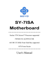
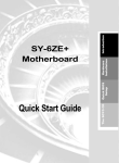
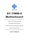
Quick Start Guide Intel 815 VGASigmatel AudioThe SOYO CD Quick BIOS Drivers Driver Setup Installation Installation Hardware Installation SY-7ISA Motherboard Introduction SOYO ™ SY-7ISA Motherboard Pentium ® III processors Intel FW82815 AGP/PCI/CNR Motherboard 66/100/133 MHz Front Side Bus supported ATX Form Factor Copyright © 2000 bySoyo Computer Inc. Trademarks: Soyo is the registered trademark of Soyo Computer Inc. All trademarks are the properties of their owners. Product Rights: All names of the product and corporate mentioned in this publication are used for identification purposes only. The registered trademarks and copyrights belong to their respective companies. Copyright Notice: All rights reserved. This manual has been copyrighted by Soyo Computer Inc. No part of this manual may be reproduced, transmitted, transcribed, translated into any other language, or stored in a retrieval system, in any form or by any means, such as by electronic, mechanical, magnetic, optical, chemical, manual or otherwise, without permission in writing from Soyo Computer Inc. Disclaimer: Soyo Computer Inc. makes no representations or warranties regarding the contents of this manual. We reserve the right to amend the manual or revise the specifications of the product described in it from time to time without obligation to notify any person of such revision or amend. The information contained in this manual is provided to our customers for general use. Customers should be aware that the personal computer field is subject to many patents. All of our customers should ensure that their use of our products does not infringe upon any patents. It is the policy of Soyo Computer Inc. to respect the valid patent rights of third parties and not to infringe upon or to cause others to infringe upon such rights. Restricted Rights Legend: Use, duplication, or disclosure by the Government is subject to restrictions set forth in subparagraph (c)(1)(ii) of the Rights in Technical Data and Computer Software clause at 252.277-7013. About This Guide: This Quick Start Guide can help system manufacturers and end users in setting up and installing the Motherboard. Information in this guide has been carefully checked for reliability; however, to the correctness of the contents there is no guarantee given. The information in this document is subject to amend without notice. For further information, please visit our Web Site on the Internet. The address is "http://www.soyo.com.tw". 7ISA Serial - Version 1.0 - Edition: September 2000 * These specifications are subject to amend without notice 2 1 Introduction Congratulations on your purchase of the SY-7ISA Motherboard. This Quick Start Guide illustrates the steps for installing and setting up your new Motherboard. This guide provides all users with the basic steps of Motherboard setting and operation. For further information, please refer to the SY-7ISA Motherboard Uses’Guide that came with your Motherboard. Unpacking When unpacking the Motherboard, check for the following items: u The SY-7ISA FW82815 AGP/PCI/CNR Motherboard u This Quick Start Guide u The Installation CD-ROM u SOYO Bonus Pack CD-ROM u One IDE Device ATA 100 Flat Cable u One Floppy Disk Drive Flat Cable 3 Introduction SY-7ISA Quick Start Guide Introduction SY-7ISA Quick Start Guide SY-7ISA Motherboard Layout PS/2 KB PS/2 Mouse Connector Connector 3 1 ATX Power JP1 USB 1 JP6 JP7 USB 2 1 2 1 1 3 3 CJ1 CJ2 1 2 PRT COM A IDE 2 IDE 1 VGA JOYSTICK 1 3 LINE-OUT CPUFAN LINE-IN CDIN1 DIMM3 4 DIMM1 1 DIMM2 AGP Slot MIC JACK FDC1 PCI#1 Intel Sigmatel STAC9721 PCI#2 JP10 PCI#3 WOL Header JP5 ITE IT8712F-A PCI#4 CMOS Clear Jumper 1 Power LED Reset LED1 LED2 LED3 LED4 PCI#5 1 2 (Optional) 3V Lithium JP9 Battery PCI#6 SYSFAN LED5 1 2 JP8 CNR1 2 14 1 13 SMCARDCN 4 1 2 5 SIRCON PWRBT Keylock STR LED HDD LED Speaker 10 JP22 1 9 USB3_4 Key Features Ø Ø Supports Intel® FC-PGA processors - FSB 66MHz: Celeron(533A700MHz) - FSB 100MHz: Pentium® III (500E850MHz) - FSB 133MHz: Pentium® III (533933MHz) Supports 66/100/133 MHz Front Side Bus Frequency Ø Auto-detect CPU voltage Ø PC99, ACPI Ø Ultra DMA33/66100 (ATA 33/66/100) Ø Ø Supports Wake-On-LAN (WOL) Support PC-100 and PC-133 SDRAM Ø Supports ACPI Suspend Indicator Ø Power-on by modem, alarm and PS/2 Keyboard Ø Battery Low voltage Detect Ø Supports multiple-boot function Ø AGP 2.0 Compliant; AGP Universal Connector supports: - 1.5V and 3.3V AGP cards - 1X/2X/4X data transfer Ø Supports Communication Networking Riser Slot (CNR 1.0 compliant) * Ø Smart Card Reader Introduction SY-7ISA Quick Start Guide - Compliant with Personal Computer Smart Card ¡ P ] C/SC ¡ W ^ orking Group standard - Compliant with smart card¡ I]SO 7816¡ ^ protocols - Supports card present detect - Supports Smart Card insertion poweron feature Ø Power failure resume Ø Supports Suspend to RAM Ø 3 x DIMM slots for SDRAM memory Ø Supports onboard hardware monitoring and includes Hardware Doctor™ utility Ø 1 x 32-bit AGP slot Ø 6 x 32-bit bus master PCI slots Ø Fan speed control Ø 4 x USB ports onboard Ø Easy CPU settings in BIOS with the “SOYO COMBO Setup” Ø 1 x IrDA port Ø Support display cache interface (AIMM card) multiplexed on the AGP interface -133MHz SDRAM interface only -4MB max addressable Ø ATX power connector * If the user wants to use a Modem Riser card (MR) make sure to use a Secondary mode MR, PRIMARY mode MRs are NOT Supported. 5 SY-7ISA Quick Start Guide 2 Installation Hardware Installation To avoid damage to your Motherboard, please follow these simple rules while handling this equipment: l Before handling the Motherboard, ground yourself by touching on to an unpainted portion of the system's metal chassis. l Remove the Motherboard from its anti-static packaging. Hold the motherboard by the edges and avoid touching its components. l Check the Motherboard for damage. If any chip appears to be loose, press carefully to seat it firmly in its socket. Follow the directions in this section which is designed to guide you through a quick and correct method to install your new SY-7ISA Motherboard. For detailed information, please refer to the SY-7ISA Motherboard User's guide and Technical Reference online manual on in the CD-ROM package that came with your Motherboard. Gather and prepare all necessary components to complete the installation successfully: u u u u u u u u u u Socket 370 processor with built-in CPU cooling fan (boxed type) SDRAM module (s) Computer case with adequate power supply unit Monitor PS/2 Keyboard Pointing Device (PS/2 Mouse) Speaker(s) (optional) Disk Drives: HDD, CD-ROM, Floppy drive… External Peripherals: Printer, Plotter, and Modem (optional) Internal Peripherals: Modem and LAN cards (optional) Note: If you want to use an external speaker connected to "Line-out" port, please make sure to use an "amplified speaker" that can generate proper output sound volume. 6 SY-7ISA Quick Start Guide Install the Motherboard Follow the steps below in order to perform the installation of your new SY-7ISA Motherboard. Step 1. Install the CPU 400MHz (66 x 6.0) 433MHz (66 x 6.5) 466MHz (66 x 7.0) 500MHz (66 x7.5) 533MHz (66 x 8.0) 566MHz (66 x 8.5) 600MHz (66 x 9.0) 633MHz (66 x 9.5) 667MHz (66 x 10.0) 700MHz (66 x 10.5) FSB 100MHz 500MHz (100 x 5.0) 550MHz (100 x 5.5) 600MHz (100 x 6.0) 650MHz (100 x 6.5) 700MHz (100 x 7.0) 750MHz (100 x7.5) 800MHz (100 x 8.0) 850MHz (100 x 8.5) 667MHz (133 x 5.0) 733MHz (133 x 5.5) 800MHz (133 x 6.0) 866MHz (133 x 6.5) 933MHz (133 x 7.0) FSB 133MHz 533MHz (133 x 4.0) 600MHz (133 x 4.5) CPU Mount Procedure: To mount the Pentium® & CeleronTM processor that you have purchased separately, follow these instructions. 1 2 3 4 1. Lift the socket handle up to a vertical position. 2. Align the blunt edge of the CPU with the matching pinhole edge on the socket. 3. Seat the processor in the socket completely and without forcing. 4. Then close the socket handle to secure the CPU in place. Remember to connect the CPU Cooling Fan to the appropriate power connector on the Motherboard. The fan is a key component that stabilizes the system. It prevents the equipment from overheating and prolongs the life of your CPU. 7 Hardware Installation Mark your CPU Frequency: Record the working frequency of your FCPGA CPU that should be clearly marked on the CPU cover. FSB 66MHz SY-7ISA Quick Start Guide Connections to the Motherboard This section tells how to connect internal peripherals and the power supply to the Motherboard. Step 2. Hardware Installation The internal peripherals consist of IDE devices (HDD, CD-ROM), Floppy Disk Drive, Chassis Fan, Front Panel Devices (STR LED, Internal Speaker, Reset Button, IDE LED, and KeyLock Switch.), Wake-On-LAN card, VGA card, Sound Card, and other devices. For more details on connecting internal and external peripherals to your new SY-7ISA Motherboard, please refer to SY-7ISA Motherboard User's Guide and Technical Reference online manual on the CD-ROM. Connectors and Plug-ins CPU Cooling Fan: CPUFAN Pin1 Pin2 Pin3 GND 12V SENSOR Chassis Fan: CHAFAN Wake-On-LAN Header: JP10 Pin1 Pin2 Pin3 Pin1 Pin2 Pin3 MP-Wakeup GND 12V SENSOR 5VSB GND Standard IrDA (Infrared Device Header): SIRCON Pin1 Pin2 Pin3 Pin4 Pin5 VCC None IRRX GND IRTX System Fan: SYSFAN Pin2 Pin3 12V SENSOR Pin1 GND USB3 Pin1 Power Pin2 Data(-) Pin3 Data(+) Pin4 GND Pin1 Power USB4 Pin3 Data(+) Pin2 Data(-) Pin4 GND Pin5 GND SMCARDCN Pin7 Pin8 Pin9 Pin10 Pin11 Pin12 Pin13 Pin14 CLK NC NC Scrio GND Scrpres NC NC Pin1 Pin2 Pin3 Pin4 CD -IN: CDIN1 Connect to your CD-ROM audio output. L GND GND R Power LED Key Lock Pin1 VCC Pin2 NC Pin3 NC Pin4 Pin5 Pin6 NC Scrfet RST Power LED Key Lock Speaker Pin1 Pin2 Pin3 5V NC GND Pin1 Pin2 Control Pin GND Speaker Reset PWRBT STR LED HDD LED Pin1 Pin2 Pin3 Pin4 5V NC NC Speaker out HDD LED STR LED PWRBT Pin1 Pin2 Pin1 Pin2 Pin1 Pin2 LED Anode LED Cathode LED Anode LED Cathode Power On/Off GND RESET Pin1 Power Good Pin2 GND ATX Power On/Off: PWRBT Connect your power switch to this header (momentary switch type). To turn off the system, press this switch and hold down for longer than 4 seconds. ATX Power Supply: ATX PW Attach the ATX Power cable to this connector. (This motherboard requires an ATX power supply, an AT power supply can NOT be used.) When using the Power-On by PS/2 Keyboard function, please make sure the ATX power supply is able to provide at least 720mA on the 5V Standby lead (5VSB). 8 SY-7ISA Quick Start Guide 5V Stand-by indicator LED (LED 5) This LED is lit whenever the 5V Standby voltage coming from the ATX powersupply is available. If you have connected your ATX powersupply to the mains, LED 5 should be lit. Step 3. Configure Memory Your board comes with two DIMM sockets, providing support for up to 512MB of main memory using unbuffered and Non-ECC DIMM modules from 32MB to 512MB, No reqistered DIMM support. Supports up to 3 Double sided DIMMs at 100MHz system memory. Supports up to 2 double sided or 3 single sided DIMMs a 133MHz system memory bus. On this motherboard, DRAM speed can be set independent from the CPU front side bus speed. Depending on the DRAM clock speed setting in the BIOS setup. Memory Configuration Table Number of Memory Modules Single-Side RAM Type Double-Side DIMM 1 DIMM 2 DIMM 3 PC100/PC133 PC100/PC133 PC100/PC133 PC100 PC100 P100 PC133 PC133 PC133 Memory Module Size (MB) PC133 32/64/128/256/512 MB Enable/Disable Power-On by Keyboard (JP1) You may choose to enable the Power-On through Keyboard function by shorting pin 1-2 on jumper JP1; or short pin 2-3 to disable this function. Step 5. Power-On by Keyboard JP1 Setting Enable Disable Short pin 1-2 to enable the PowerOn by Keyboard function. Short pin 2-3 and the Power-On by Keyboard function is disabled. 1 2 3 1 2 3 Important: When using the Power-On by Keyboard function, please make sure the ATX power supply is able to provide at least 720mA on the 5V Standby lead (5VSB) in order to meet the standard ATX specification. 9 Hardware Installation Step 4. SY-7ISA Quick Start Guide Step 6. CNR MR Card-CODEC OPTION (JP8) Hardware Installation CNR MR Card-CODEC OPTION JP8 Setting Primary Secondary open JP8 short JP8 1 2 1 2 Set JP9 for FWH Boot Block Write-Protect Setting this jumper to open will prevent the boot block area of the FWH (FirmWare Hub) chip from being written data into such that it is write-protected from unwanted or abnormal write activity. Step 7. Note: In some rare cases, the boot block area will need to be flashed to complete the BIOS upgrade procedure. Setting JP9 to open will cause incomplete BIOS update in that case. The FWH Boot Block Write-Protect JP9 Setting Locked Unlocked open JP9 short JP9 1 2 1 2 SPEAKER OPTION (JP22) Through this jumper the case speaker output can be redirected to the external (amplified) speakers (if connected) through the on-board Audio-Codec. Step 8. SPEAKER OPTION JP22 Setting Lineout SPK Short pin 1-2 CASE SPK Short pin 2-3 1 2 3 10 1 2 3 SY-7ISA Quick Start Guide Step 9. CPU Frequency Settings: JP6, JP7, CJ1 and CJ2 For certain Intel CPUs, the multiplier is not locked such that setting a multiplier higher than specified on the CPU is possible. For technical details read the following: However, the FSB Frequency can also be set through jumpers CJ1 and CJ2 and it may therefore differ from the Frequency the CPU specifies. If CJ1 and CJ2 are to be used, JP6 & JP7 must be open. Doing so may however force your CPU to operate out of its specifications and therefore SOYO can not guarantee the proper functioning of your system. Refer to the following table: CPU Frequency Automatic JP6 JP7 Short Short Open Open 1 2 Manual 100MHz Open Open 2-3 1-2 Open 1 2 3 2-3 1 2 3 1-2 1 2 1 2 3 1 2 3 1 2 1 2 Open 2-3 Open CJ2 1 2 3 1 2 1 2 133MHz Open 1 2 1 2 66MHz CJ1 1 2 3 1-2 1 2 3 1 2 3 CMOS Clear (JP5) In some cases the CMOS memory may contain wrong data, follow the steps below to clear CMOS memory. 1. Clear the CMOS memory by momentarily shorting pin 2-3 on jumper JP5. This jumper can be easily identified by its white colored cap. 2. Then put the jumper back to 1-2 to allow writing new of data into the CMOS memory. CMOS Clearing JP5 Setting Clear CMOS Data Retain CMOS Data Short pin 1-2 to retain new settings Short pin 2-3 for at least 5 seconds to clear the CMOS 1 2 3 1 2 3 Note: You must unplug the ATX power cable from the ATX power connector when performing the CMOS Clear operation. 11 Hardware Installation Your FC-PGA 133/100/66 MHz FSB CPU has a pin JP6, JP7 to tell it what FSB frequency the CPU requires; If these two jumpers are shorted the motherboard will automatically run at the frequency the CPU was specified to run at. SY-7ISA Quick Start Guide Debug LEDs The Debug LEDs give an indication of the status of the system during boot-up. If the system does not boot-up properly, use the table below to find out at what point in boot-up sequence the problem arises. A x means the LED is off, a L means the LED is lit. Code Hardware Installation X Explanation X X L LED4 LED3 LED2 LED1 X X L X LED4 LED3 LED2 LED1 X X L L LED4 LED3 LED2 LED1 X L X X Initialization of the chipset. The MCH and ICH registers will be set to the most conservative values by the BIOS to make sure the system boots up properly. The BIOS is now decompressing the BIOS code into shadow RAM. Most of the BIOS code is stored in the BIOS Flash ROM IC in compressed form to save space. At boot-up this code is decompressed and stored to RAM for faster execution. The checksum for the decompressed code is calculated and checked. The checksum is calculated by adding all data bytes together and storing the result in the BIOS ROM. If the calculated checksum is different from the checksum stored in the ROM, the code stored in the FLASH ROM is corrupted. The chipset (MCH and ICH) registers are set to the values selected by the user. LED4 LED3 LED2 LED1 X L X L Now the BIOS will set the CPU Vcore voltage and the FSB bus frequency to the user selected value. If the system stops at this point, the settings selected by LED4 LED3 LED2 LED1 the user are inappropriate. Please select more conservative settings. X L L X The Hardware Monitor Functionality is initialized. The settings the user selected in the BIOS for the Hardware Monitor are written into the Hardware LED4 LED3 LED2 LED1 Monitor registers. X L L L If the VGA card does not work or is not inserted at all, the system will display LED4 LED3 LED2 LED1 this code for a short period of time. L X X X At this point the BIOS is initializing the CPU. The L2 cache latency values are LED4 LED3 LED2 LED1 set, and more important, the CPU micro-code is written into the CPU. L X X L Now the system is testing the RAM inserted on the board. The screen will show the BIOS testing the RAM by a running counter. After finishing the test, LED4 LED3 LED2 LED1 the screen will show the amount of RAM in your system. L X L X The super I/O registers are set to the default values. This includes the serial, LED4 LED3 LED2 LED1 parallel and IR etc settings. L X L L At this point the IDE busses (primary and secondary) are scanned for devices. This includes HD drives and ATAPI CD-ROM drives that are connected to LED4 LED3 LED2 LED1 the IDE bus. After scanning the detected devices are displayed on screen. L L X X The serial and parallel port registers are set to the values selected by the user. LED4 LED3 LED2 LED1 L L X L Now the BIOS will scan the peripheral busses for add-on cards. This includes the PCI and AGP busses. If any add-on cards are detected, the resources it LED4 LED3 LED2 LED1 requires are assigned by the BIOS in accordance with user settings. L L L X The ESCD and DMI (Desktop Management Interface) values are checked. If there are changes, the BIOS will flash the new values into the BIOS Flash LED4 LED3 LED2 LED1 ROM IC. L L L L At this point the BIOS passes control to the Operating System (OS). All LEDs LED4 LED3 LED2 LED1 will be on and will stay on to indicate a successful boot. 12 SY-7ISA Quick Start Guide 3 Quick BIOS Setup This Motherboard does not require any hardware jumpers to set the CPU frequency. Instead, CPU settings are software configurable through the BIOS [Frequency/Voltage Control]. The [Frequency/Voltage Control] menu combines the main parameters that you need to configure your system. They are all in one menu to enable a quick setup in BIOS. Step 1. Select [Standard CMOS Features] Set [Date/Time] and [Floppy drive type], then set [Hard Disk Type] to “Auto”. Step 2. Select [Load Optimized Defaults] Select the “Load Optimized Defaults”menu and type “Y”at the prompt to load the BIOS optimal setup. Step 3. Select [Frequency/Voltage Control] Move the cursor to the [CPU Frequency] field to set the CPU frequency. Available [CPU Frequency] settings on your SY-7ISA Motherboard are detailed in the following table. If you set this field to [Manual], you are then required to fill in the next two consecutive fields: (1) the CPU Host/PCI Clock, and (2) the CPU Ratio. CPU Frequency (MHz) 633MHz (66 x 9.5) 800MHz (100 x 8.0) Manual 400MHz (66 x 6.0) 433MHz (66 x 6.5) 466MHz ( 66 x 7.0) 500MHz( 66 x 7.5) 533MHz ( 66 x 8.0) 566MHz ( 66 x 8.5) 600MHz ( 66 x 9.0) 667MHz (66 x 10.0) 700MHz (66 x 10.5) 500MHz (100 x 5.0) 550MHz (100 x 5.5) 600MHz (100 x 6.0) 650MHz (100 x 6.5) 700MHz(100 x 7.0) 750MHz (100 x 7.5) 850MHz (100 x 8.5) 600MHz (133 x 4.5) 666MHz (133 x 5.0) 733MHz (133 x 5.5) 800MHz (133 x 6.0) 866MHz (133 x 6.5) 933MHz (133 x 7.0) Select the working frequency of your Pentium® III, Celeron processor among these preset values. Note: Mark the checkbox that corresponds to the working frequency of your Pentium® III, Celeron processor in case the CMOS configuration should be lost. Step 4. Select [SAVE & EXIT SETUP] Press <Enter> to save the new configuration to the CMOS memory, and continue the boot sequence. 13 Quick BIOS Setup After completion of hardware installation, turn the power switch on, then press the <DEL> key while the system diagnostic is checking to enter the Award BIOS Setup program. The CMOS SETUP UTILITY will be displayed on screen. Then follow these steps to configure the CPU settings. SY-7ISA Quick Start Guide The SOYO CD 4 The SOYO-CD will NOT autorun if you use it on an Operating System other than Windows 9x or NT. Your SY-7ISA Motherboard comes with a CD-ROM labeled "SOYO CD." The SOYO CD contains (1) the user's manual file for your new Motherboard, (2) the drivers software available for installation, and (3) a database in HTML format with information on SOYO Motherboards and other products. Step 1. Insert the SOYO CD into the CD-ROM drive The SOYO CD will auto-run, and the SOYO CD Start Up Menu will be as shown. The SOYO CD If you use Windows NT, the SOYO-CD will not detect your motherboard type. In that case the following dialog will pop up, please choose your motherboard and press OK. Now the SOYO-CD Start Up Menu will be shown. X Please Select Your Board LI-7000 7IWB 7IWB V1.0 7IWM 7IWM/L V1 7IWA-F 7IWA-F V1.0 6IWM/L 6IWM 6IWA Cancel OK (SOYO CD Start Up Program Menu) If you use Windows 95 or 98, the SOYO CD Start Up Program automatically detects which SOYO Motherboard you own and displays the corresponding model name. 14 The user's manual files included on the SOYO CD are in PDF (Postscript Document) format. In order to read a PDF file, the appropriate Acrobat Reader software must be installed in your system. Note: The Start Up program automatically detects if the Acrobat Reader utility is already present in your system, and otherwise prompts you on whether or not you want to install it. You must install the Acrobat Reader utility to be able to read the user's manual file. Follow the instructions on your screen during installation, then once the installation is completed, restart your system and re-run the SOYO CD. Step 2. Install Drivers and Utilities Click the Install Drivers button to display the list of drivers software that can be installed with your Motherboard. The Start Up program displays the drivers available for the particular model of Motherboard you own. We recommend that you only install those drivers. 15 The SOYO CD SY-7ISA Quick Start Guide SY-7ISA Quick Start Guide driver revision: Intel .inf utility for Win 9x Intel Ultra ATA Storage Drive for Win 98/98SE/NT Intel 815 VGA Drivers for Win 9x Intel 815 VGA Drivers for Win NT Sigmatel Audio Driver Sigmatel Staggato Gold Application 7ISA ITE hardware doctor for Win 9x/2000/NT Cancel OK (Driver Installation Menu) A short description of all available drivers follows: The SOYO CD Ø Intel .inf utility for Win 9x Windows 95 and 98 will not recognize the new INTEL 815 chipset properly. To update the necessary .inf files that will help Windows recognize the 815 chipset, please run this utility. Ø Intel Ultra ATA Storage Driver for Win 98/98SE/NT The Intel Ultra ATA Storage Driver automatically enables fast Ultra ATA transfers for a variety of ATA/ATAPI mass storage devices such as hard disk drives and CD-ROMs. Ø Intel 815 VGA Drivers for Win9x In order to be able to make use of the integrated VGA function in your Intel 815 chipset, you will need to install this driver first. For Windows 95/98 only. Ø Intel 815 VGA Drivers for NT 4.0 In order to be able to make use of the integrated VGA function in your Intel 815 chipset, you will need to install this driver first. For NT 4.0 only. Ø Sigmatel Audio Driver This AC codec sound driver is for Windows 9x, 2000 and NT. Ø Sigmatel Staggato Gold Application This application contains the wavetable that is necessary to play MIDI files. Make sure to install it after installing the Sigmatel drivers for your OS. (Refer to the manual installation guide in the back.) This application is suitable for Windows 95, 98(SE) and NT. 16 SY-7ISA Quick Start Guide Ø 7ISA ITE hardware doctor for Win 9X/2000/NT Your motherboard comes with a hardware monitoring IC. By installing this utility Temperature, Fan speed and Voltages can be monitored. It is also possible to set alarms when current system values exceed or fall below pre-set values. Select which driver you want to install and click OK, or click Cancel to abort the driver installation and return to the main menu. Note: Once you have selected a driver, the system will automatically exit the SOYO CD to begin the driver installation program. When the installation is complete, most drivers require to restart your system before they can become active. Step 3. Check the Latest Releases The SOYO CD Click the 'Check the latest Releases' button to go the SOYO Website to automatically find the latest BIOS, manual and driver releases for your motherboard. This button will only work if your computer is connected to the internet through a network or modem connection. Make sure to get your modem connection up before clicking this button. 17 SY-7ISA Quick Start Guide 5 Sigmatel Audio Driver Installation Installing the Sigmatel Audio Drivers under windows 95/98, Windows 98 Second Edition, Windows 2000 and Windows NT You have to install the drivers before installing any application for the AC97 codec. Uninstalling/Re-Installing Sigmatel Audio Drivers for Windows 9x 1. Open Device Manager. 2. Remove the Sigmatel Audio Codec entry in the Sound, Video, and Game Controllers section. Do not change the game controller in this audio solution. 3. Delete the sigmatel INF file in c:\windows\inf\other 4. Restart your PC for Plug and Play to reinitialize your system. Uninstalling or Updating the Sigmatel Audio Drivers for Windows NT 1. Sigmatel Audio Driver Installation 2. 3. 4. 5. Double click on the MULTIMEDIA icon in the control panel. Select the Devices tab from the Multimedia properties window. Double click on the Audio Devices entry from the Multimedia devices list. Select the driver by placing the mouse pointer over the sigmatel driver label and clicking the left mouse button. Press the REMOVE button. A question box will appear to verify your decision. Press the YES button. Windows NT will display a dialog box asking you to restart your system. Press the Restart Now button to complete the Un-installation. 18 SY-7ISA Quick Start Guide SynthCore Lite Application for Windows NT 4.0 The CD contains a SynthCore Lite application program, that the Quick Start Guide does not describe. It can be installed by running StacGold.exe in the D:\drive-all\sigmatel\StacGold directory. (Were D is your CD-ROM drive letter). Note that the NT4 installation requires a manual step at the end of the installation. This step apllies to NT4 only. (NT4 Service Pack 4 has to be installed, Service Pack 4 includes DirectSound 3) Sigmatel Audio Driver Installation 1) After you run the normal installer, DO NOT reboot your system yet. 2) Go to Start > Settings > Control Panel > Multi Media 3) Select the "Devices" tab 4) Select the "Add" Button 5) Select "Unlisted or Undated Driver" 6) Browse to c:\Program Files\Staccato\SynthCore Lite\oemsetup.inf and select this file. 7) Now look under the MIDI Devices tab, you should see the Staccato MIDI driver. 8) Reboot your machine. This finishes the installation process. 19 SY-7ISA Quick Start Guide 6 Intel 815 VGA Drivers Installation (For Windows 2000) INSTALLING THE SOFTWARE General Installation Notes: 1. The operating system must be installed on the system prior to installation. 2. This installation procedure is specific only to the version of driver and installation file included in this release. 3. This procedure assumes that all of the software associated with this release is located in the same directory. ntel 815 VGA Drivers Installation MANUAL INSTALL FROM HARD DRIVE 1. Download WIN2KCD.ZIP from the Web. Double-click to unzip. (You must have WinZip* installed; download it from www.winzip.com). Hit the Extract button and indicate the directory into which the files are to be extracted. Hit the Extract button to unzip the files to that directory. If you wish to install from the CD-ROM, then the files must be transferred to a CD. 2. Select the My Computer icon. 3. Select the Control Panel icon. 4. Select the System icon. 5. You should be in the System Properties window. 6. Click on the Hardware tab. 7. Click the Device Manager button. 8. Click the Display Adapters selection. 9. The current list of adapters is displayed. 10. Click on the adapter (e.g., VGA) that the Intel Win2K driver is replacing. 11. Click on the Driver tab. 12. Click the Update Driver... button. 20 SY-7ISA Quick Start Guide 13. The Upgrade Device Driver Wizard window should now open. 14. Click the Next button. 15. Select the following option: "Display a list of the known drivers for this device so that I can choose a specific driver". 16. Click the Have Disk button. 17. Click on "Browse" and go to the directory where the files were unzipped. Go to the Win2K directory. If the English version of the driver is to be installed, select the i81xnt5.INF file and press OK. If another language is desired, select the INF folder, and the select the INF file of the desired language. 18. Proceed according to the remaining prompts. Close all windows and reboot in order to use the new driver. See "Verifying the Installation of the Software" below to confirm that the proper driver is being used. VERIFYING THE INSTALLATION OF THE SOFTWARE From the Microsoft Windows 2000 desktop, click on "My Computer", then "Control Panel", and then "System". 2. You should be in the System Properties window. Click on the Hardware tab and hit the Device Manager button. From here, go down to "Display Adapter" and click. 3. The installed display adapter should be Intel Corporation 815 Graphics Controller Hub. Intel 815 VGA Drivers Installation 1. 21 SY-7ISA Quick Start Guide Quick Trouble shoot tips Video (no display) related issues I built a new computer system using a Soyo board and nothing happens when turning it on, no video and no beeps from the PC speaker. What is happening and how can it be fixed? No screen and no beeps mean that your CPU and motherboard do not work at all. It could be that the CPU is not seated correctly or that a component on the M/B is grounded (shorted) with the case. Also make sure to check the voltage setting switch (110V/220V) on the back of the power supply. To isolate the problem do the following: 1. Press and hold down on the “Ins” (insert) key while turning on the computer until you get video. If you do not get video then, 2. Double-check jumpers setting on you motherboard and remove all add-on cards, unplug all hard-disk and floppy-disk drive cables and see if you can hear some beeps. If you still do not get any beeps, then try putting the motherboard on the table (to isolate it from the case) with the CPU and speaker only, and give it one more try. I hear a series of beeps and I do not get anything from my monitor. What could be wrong? The following lists some basic beep codes and their possible meanings: • One long beep and 3 very short beeps - The video card is not detected by the motherboard. Please re-seat your video card. If you are using an AGP card, please push your AGP card down real hard. You may have to push VERY hard without the AGP card mounting screw. Make sure not to insert the card the other way around. • Continuous beeps – One or more of the memory modules is not seated correctly in its socket. My PCI VGA card works fine with my system, but when I put in a new AGP card, it does not give me any video. Is my AGP slot bad? This is a common problem with AGP video cards. The reason is that your AGP card did not get seated into the AGP slot fully and firmly. Please push your AGP card down into the socket real hard, it should snap twice. You may have to unscrew the AGP card to allow the card to go further down. Do take care not to damage the card by using too much force. 22 SY-7ISA Quick Start Guide I get distorted video my AGP card right after I save my bios. Why is that? The cause is likely that your AGP card is not running at the correct bus speed. To fix this, please clear the CMOS via JP5 and if it still does not work, please upgrade your motherboard bios to the latest version. BIOS Issues Where can I find the BIOS revision of my mainboard? It will be displayed on the up-left corner on the screen during boot-up. It will show as your board type followed by the revision number, such as 5EH_2CA1 (meaning revision 2CA1 for the SY-5EH board) or 6BA+ IV_2AA2 which means SY-6BA+ IV motherboard with 2AA2 bios. Where can I find the latest BIOS of my motherboard? Please go to the technical support page of one of the SOYO websites (Taiwan: www.soyo.com.tw), and look up your motherboard to find the latest BIOS revision. Hard disk, floppy drive, CD-ROM etc When I boot up my new computer I got "floppy boot failure" and the LED on the floppy stays on Make sure the red wire of floppy ribbon cable goes to Pin1 on the floppy drive side (don't trust the "key lock" or "notch") and use the end-connector of the cable (don't use middle one). Modem issues I get an "I/O Conflict" message when I turn on my system and I can not get my modem to work What you need to do is to disable 'COM2' (or UART2 or serial port 2) in the bios under integrated peripheral setup. I have installed my modem drivers several times and I still cannot get my modem to work. Why? If you are sure that the modem driver has been installed correctly, then you need to install the south bridge driver from the SOYO CD, this is because Windows does not properly recognize relatively new chipsets. Audio Issues I do not get any sound from my sound card. What could be wrong? Please make sure the speaker is connected to the speaker out port on your sound card. 23 SY-7ISA Quick Start Guide In Device Manager, I keep getting yellow exclamation signs on my sound port even though I have installed my sound driver several times and I could not get my sound card to work. What is wrong? It is likely that you did not have the correct driver installed. If you are sure that the correct sound driver has been installed, then please install the 'south bridge' driver for the motherboard. The sound is working in my system, but when I play CD music from the CDROM, I do not get any sound. What is wrong? This is because the 3-wire audio cable from the CD-ROM to the sound card is not connected or it is loose. The sound from my sound card is distorted when Windows starts. What is wrong? First, if you are using an ISA sound card, please make sure the IRQ needed for the sound card is set to 'Legacy ISA' in the bios. In other words, if your ISA sound card takes IRQ5, then set IRQ5 to 'Legacy ISA'. Next, install the 'south bridge' driver for the motherboard. The sound and everything else works fine except that the recorder and microphone do not work. What is wrong? This is because the recorder and microphone in the Windows are not enabled. Please go to sound properties and enable them. Lock up (freeze) When I boot up my system, everything works fine. It sees my CPU and memory, detects my hard drive, floppy drive and CD-ROM but locks up at "Verify DMI pool data... ", and it won’t go any further. What should I do? Please clear the CMOS via JP5 then choose 'load setup default' in the bios and save the bios and exit. Next, unplug all other add-on cards except the video card and floppy drive controller, and see if it can boot from floppy. Then put back the peripherals one by one to identify which one causes the lockup. If you are running a Cyrix CPU, make sure the 'linear burst function' is enabled in the bios. I can not get my board to run properly. Please make sure you have the latest bios and driver from the SOYO web site at: http://www.soyo.com 24 SY-7ISA Quick Start Guide How to contact us: n If you are interested in our products, please contact the SOYO sales department in the region you live. n If you require Technical Assistance, please contact our Technical Support in the region you live. SOYO prefers Email as communication medium, remember to always add to the email the country that you live in. SOYO Taiwan SOYO USA No. 21 Wu-Kung 5 Rd., Hsin Chuang City, Taipei Hsien, Taiwan 41484 Christy Street, Fremont, CA 94538 Region Covered: US and Canada Region Covered: Taiwan and AsiaPacific. (Including Australia). Web Site: www.soyousa.com, www.soyo.com Web Site: www.soyo.com.tw Sales: Email : [email protected] Sales: Tel: 886-2-22903300 Fax: 886-2-22983322 E-mail: [email protected] Technical Support: Support Web Site: www.soyousa.com/support.htm Technical Support: Fax: 886-2-22983322 E-mail: [email protected] SOYO (U.K.) LTD. Unit 7, Alice Way, Hounslow Business Park, Hanworth Road, Hounslow, TW3 3UD SOYO Europe BV Signaalrood 19, 2718 SH Zoetermeer The Netherlands Region Covered: United Kingdom and Republic of Ireland Region Covered: Europe except Germany and United Kingdom Web Site: www.soyo.co.uk Sales: Tel : +44 (0)181 569 4111 Fax: +44 (0)181 569 4134 E-mail: [email protected] Web Site: www.soyo.nl, www.soyoeurope.com Sales: Tel: +31-69-3637500 Fax: +31-79-3637575 Email: [email protected] Technical Support: Tel : +44 (0)181 569 4111 Fax: +44 (0)181 569 4134 E-Mail: [email protected] Technical Support: Tel : +31-79-3637500 Fax: +31-79-3637575 Email: [email protected] 25 SY-7ISA Quick Start Guide SOYO Deutschland GmbH SOYO Hong Kong August-Wilhelm-Kuhnholz-Str. 15 D-26135 Oldenburg Region Covered: Hong Kong Region Covered: Germany, Sales: tel: 852-27109810 fax: 852-27109078 E-mail: [email protected] Web Site: www.soyo.com.hk Web Site: www.saat.de, www.soyosaat.com, www.soyo-saat.de Vertrieb Mainboards, Notebooks und SoyoCom Produkte: E-Mail: [email protected] Fon: +49-(0)441/20910-31/33 Fax: +49-(0)441/203422 Technical Support: tel: 852-27109810 fax: 852-27109078 E-mail: [email protected] Technischer Support: E-Mail: [email protected] Fon: +49-(0)441/20910-40 Fax: +49-(0)441/203422 SOYO China (Gin Mei Jei) Region Covered: All of China Sales: Tel: 86-10-62510089 fax: 86-10-62510388 E-mail: [email protected] SOYO KOREA Region Covered: Korea Web site: www.soyo.co.kr Sales: Tel : 82-2-716-2850 Fax : 82-2-704-2619 E-mail : [email protected] Technical Support: Tel: 86-10-62510089 fax: 86-10-62510388 E-mail: [email protected] Technical Support: tel : 82-2-717-4392 fax : 82-2-712-5853 E-mail : [email protected] SOYO Japan Region Covered: Japan Web site: www.soyo.co.jp Sales: Tel: 81-3-33682188 Fax: 81-3-33682199 E-mail: [email protected] Technical Support: Tel: 81-3-33682188 Fax: 81-3-33682199 E-mail: [email protected] 26 Edition: September 2000 Version 1.0 SY-7ISA SERIAL