1
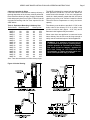
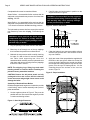
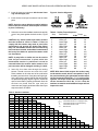
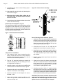
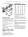
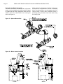
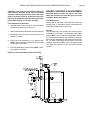
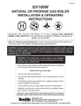
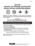
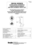
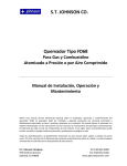
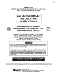
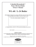
28HE-IOM-1
SERIES 28HE
GAS OR OIL BOILER
INSTALLATION & OPERATING
INSTRUCTIONS
DESIGNED AND TESTED ACCORDING TO A.S.M.E. BOILER AND PRESSURE
VESSEL CODE, SECTION IV FOR A MAXIMUM ALLOWABLE WORKING PRESSURE
OF: 15 PSI STEAM OR 80 PSI WATER.
TO INSTALLER
NOTE: READ THESE INSTRUCTIONS CAREFULLY. THEY WILL
SAVE YOU VALUABLE TIME WHEN ASSEMBLING THE BOILER.
WARNING: If the information in this manual is not followed exactly, a fire or explosion
may result causing property damage, personal injury or loss of life.
Do not store or use gasoline or other flammable vapors and liquids in the vicinity of
this or any other appliance.
WHAT TO DO IF YOU SMELL GAS:
• Do not try to light any appliance.
• Do not touch any electrical switch. Do not use any phone in your building.
• Immediately call your gas supplier from a neighbor’s phone. Follow the gas
supplier’s instructions.
• If you cannot reach your gas supplier, call the fire department.
Installation and service must be performed by a qualified installer, service agency or
the gas supplier.
INSTALLER, THESE INSTRUCTIONS TO BE AFFIXED ADJACENT TO THE BOILER.
CONSUMER, RETAIN THESE INSTRUCTIONS FOR FUTURE REFERENCE PURPOSES.
FOR JACKET ASSEMBLY AND BURNER SET UP SEE SEPARATE INSTRUCTIONS.
WESTCAST, INC.
260 NORTH ELM STREET WESTFIELD, MA 01085
TEL. (413) 562-9631 FAX (413) 562-3799
In Canada: 5211 Creekbank Road, Mississauga, Ont. L4W 1R3 (905) 625-2991 Fax (905) 625-6610
Page 2
SERIES 28HE BOILER INSTALLATION AND OPERATION INSTRUCTIONS
CONTENTS
Before You Start ................................................. page 2
Boiler Ratings & Capacities ................................ page 2
Boiler Location ................................................... page 2
Combustion Air & Ventilation .............................. page 3
Chimney & Vent Pipe Connections .................... page 4
Common Vent Systems ...................................... page 6
Boiler Assembly ................................................ page 7
General Piping Requirements .......................... page 14
Water Boiler Piping .......................................... page 15
Steam Boiler Piping .......................................... page 18
Burner Installation ............................................ page 21
Electrical Wiring ............................................... page 22
Boiler Operation .............................................. page 22
Boiler Checking & Adjustment .......................... page 23
Boiler Maintenance .......................................... page 24
Repair Parts ..................................................... page 25
Health Warnings .......................................... back cover
BEFORE YOU START
This manual covers the assembly, installation, operation
and maintenance of a Series 28HE low pressure steam
or hot water boiler.
The 28HE Series boilers are supplied completely
knocked down for field assembly, knocked down but with
an assembled block or as complete factory assembled
packaged boilers. All boiler components should be
inspected for damage upon receipt. Any damage should
be immediately reported to the trucker or wholesaler. All
boiler components should be stored in a clean dry area.
To obtain the safe, dependable, efficient operation and
long life for which this boiler was designed, these
instructions must be read, understood and followed.
In Canada, the installation must be in accordance with
the requirements of CAN/CGA B149.1 or .2, Installation
Code for Gas Burning Appliances and Equipment.
In the Commonwealth of Massachusetts the installation
of a gas burner must be performed by a licensed
plumber or gas fitter.
The owner should maintain a record of all service work
performed with the date and a description of the work
done. Include the name of the service organization for
future reference.
Direct all questions to your Smith Cast Iron Boiler
distributor or contact the Smith Customer Service
Department. Always include the model and serial
numbers from the rating plate of the boiler in question.
BOILER RATINGS & CAPACITIES
Before undertaking the installation of the 28HE Series
boiler check the boiler rating plate to ensure that the
boiler has been sized properly for the job. The “Net
I=B=R Ratings” specify the equivalent amount of direct
cast iron radiation that the boiler can supply under
normal conditions. Also ensure that the boiler has been
set up for the type of fuel available at the installation
site.
BOILER LOCATION
1.
Locate the boiler in an area that provides good
access to the unit. A minimum distance of 6 in,
0.15m must be maintained between the boiler
and combustible construction. Servicing may
require the removal of jacket panels so service
clearances should be maintained. Allow a minimum
clearance of 3 ft, 0.9 m between adjacent
construction and the left side, front and smoke hood.
A minimum clearance of 2 ft, 0.6 m should be
maintained between adjacent construction and the
right side and back of the boiler. Accessibility
clearances should take precedence over minimum
clearances to combustible construction, Figure 1.
2.
An optimum site will be level, central to the piping
system, close to a chimney and have adequate
fresh air for combustion.
3.
The boiler should be installed on a level, flat,
concrete floor or pad that is structurally sound and
will support the weight of the boiler. If a concrete
pad is used it must be at least 2" thick. Never install
the boiler on a concrete floor or pad that contains
wires, cables, water pipes or hoses. This boiler is
designed for non combustible floors!
The Series 28HE boilers have been design certified by
CSA. Each unit has been constructed and hydrostatically tested for a maximum working pressure of 15
psi for steam, 80 psi for water, in accordance with
Section IV of the A.S.M.E. Boiler and Pressure Vessel
Code for cast iron boilers.
All aspects of the boiler installation must conform to the
requirements of the authority having jurisdiction, or, in
the absence of such requirements, to the National Fuel
Gas Code, ANSI Z223.1/NFPA 54-latest revision or to
the Installation of Oil Burning Equipment, ANSI/NFPA
31.
Where required by the authority having jurisdiction, the
installation must conform to the Standard for Controls
and Safety Devices for Automatically Fired Boilers,
ANSI/ASME CSD-1.
SERIES 28HE BOILER INSTALLATION AND OPERATION INSTRUCTIONS
Page 3
Figure 1 -Service Clearances to Adjacent Construction
WARNING: Never install a 28HE boiler on top of
combustible flooring without consulting the
local building authorities for proper installation
guidelines! A minimum clearance of 6 in,
0.15 m must be maintained between the boiler
and combustible construction. Failure to comply
with this warning may result in a fire causing
extensive property damage, severe personal
injury or death!
4.
DO NOT install this boiler in a location that would
subject any of the electrical components to direct
contact with water or excessive moisture during
operation or servicing.
5.
DO NOT place this boiler in a location that would
restrict the introduction of combustion air into the
boiler.
WARNING: Never store combustible materials,
gasoline or any product containing flammable
vapors or liquids in the vicinity of the boiler.
Failure to comply with this warning can result
in an explosion or fire causing extensive
property damage, severe personal injury or
death!
COMBUSTION AIR & VENTILATION
WARNING: This boiler must be supplied with
combustion and ventilation air in accordance
with Section 5.3, Air for Combustion &
Ventilation, of the latest revision of the National
Fuel Gas Code, ANSI Z223.1/NFPA 54 and all
applicable local building codes. Canadian
installations must comply with CAN/CGA B149.1
or .2 Installation Code. Failure to provide
adequate combustion air for this boiler can
result in excessive levels of carbon monoxide
which can result in severe personal injury or
death!
To operate properly and safely this boiler requires a
continuous supply of air for combustion. An adequate
supply of air must be available to replace the air used
by the combustion process. NEVER store objects on or
around the boiler.
CAUTION: Never use an exhaust fan in the boiler
room. The boiler room must never be under a
negative pressure or improper burner operation will
occur!
NOTE: Forced make-up air supplied to the boiler
room must be approved by the local authorities.
A minimum of 30 ft 3 /GAL, 0.22 m 3 /L for oil or
20 ft3/100 MBH (Therm), 0.024 m3/kW for gas must
be provided.
Page 4
SERIES 28HE BOILER INSTALLATION AND OPERATION INSTRUCTIONS
All Air From Inside The Buidling
If the boiler is to be located in a confined space minimum clearances of 24 in, 610 mm must be maintained
between the boiler and any adjacent construction. When
installed in a confined space, two permanent openings
communicating with an additional room(s) are required.
The combined volume of these spaces must have
sufficient volume to meet the criteria for an unconfined
space. The total air requirements of all fuel burning
equipment or any type of exhaust fan must be
considered when making this determination.
Each opening must have a minimum free area of 1 in2/
1000 Btu/hr, 140 in2/GPH, 2200 mm2/kW based on the
total input rating of ALL fuel burning equipment in the
confined area. Each opening must be no less than 100
in2, 64,516 mm2 in size. The upper opening must be
within 12 in, 305 mm of, but not less than 3 in, 76 mm
from, the top of the enclosure.
The bottom opening must be within 12 in, 305 mm of,
but not less than 3 in, 76 mm from, the bottom of the
enclosure.
All Air From Outside The Building
When installed in a confined space Two permanent
openings communicating directly with, or by ducts to,
the outdoors or spaces that freely communicate with the
outdoors must be present. The upper opening must be
within 12 in, 305 mm of, but not less than 3 in, 76 mm
from, the top of the enclosure. The bottom opening must
be within 12 in, 305 mm of, but not less than 3 in,
76 mm from, the bottom of the enclosure.
Where directly communicating with the outdoors or
communicating with the outdoors through vertical ducts,
each opening shall have a minimum free area of 1 in2/
4000 Btu/hr, 35 in2/GPH, 550 mm2/kW of the total input
rating of all of the equipment in the enclosure.
Where communicating with the outdoors through
horizontal ducts, each opening shall have a minimum
free area of 1 in2/2000 Btu/hr, 70 in2/GPH, 1100 mm2/
kW of the total input rating of all of the equipment in
the enclosure. When ducts are used, they must have the
same cross-sectional area as the free area of the
opening to which they connect. When calculating the
free area necessar y to meet the make-up air
requirements of the enclosure, consideration must be
given to the blockage effects of louvers, grills and
screens. Screens must have a minimum mesh size of
1/4 in, 6.4mm. If the free area through a louver or grill
is not known the louver or grille should be sized per
Table 1.
Table 1 - Make-up Air Louver Sizing
Required Cross Sectional Area (in2)
Metal
Wooden
Input
1/4" Wire
Louvers
Louvers
(MBH)
Screen
75% Free Area
25% Free Area
1000
250
333
1000
1200
300
400
1200
1400
350
467
1400
1600
400
533
1600
1800
450
600
1800
2000
500
667
2000
2200
550
733
2200
2400
600
800
2400
2600
650
867
2600
2800
700
934
2800
3000
750
1000
3000
3200
800
1066
3200
3400
850
1134
3400
3600
900
1200
3600
3800
950
1267
3800
4000
1000
1334
4000
4200
1050
1400
4200
4400
1100
1467
4400
4600
1150
1533
4600
4800
1200
1600
4800
CHIMNEY & VENT PIPE
CONNECTIONS
WARNING: The vent installation must be in
accordance with Part 7, Venting of Equipment,
of the National Fuel Gas Code, ANSI Z223.1/
NFPA 54-latest revision, the ASHRAE Equipment
Handbook on Venting or applicable provisions
of the local building codes. Canadian
installations must comply with CAN/CGA B149.1
or .2 Installation Code. Improper venting of this
boiler can result in excessive levels of carbon
monoxide which can result in severe personal
injury or death!
CAUTION: The products of combustion from a 28 HE
must be safely vented to the outdoors while
ensuring that the flue gasses do not cool
prematurely. It’s critical that the chimney system be
properly designed to handle the relatively cool flue
gas temperatures. An oversized or uninsulated
chimney will cause the moisture in the flue gases
to condense resulting in damage to the chimney
system unless it’s specifically designed for
condensate. If this is the case a suitable condensate
drain must be used to protect the boiler from
condensate.
NOTE: Our warranty does not cover corrosion
damage to the boiler or its vent system caused by
flue gas condensate!
SERIES 28HE BOILER INSTALLATION AND OPERATION INSTRUCTIONS
Page 5
Chimney Inspection & Sizing
If this boiler will be connected to a masonry chimney, a
thorough inspection of the chimney must be performed.
Ensure that the chimney is clean, properly constructed,
lined and properly sized, see Figure 2. Table 2 lists the
equivalent breeching and flue sizes required for the
28HE boilers.
The 28HE is designed for pressurized operation with a
back pressure of 0.10 in, 2.54 mm W.C. before the
smoke hood slide damper. If the vent configuration
results in a back pressure greater than this, the burner
capacity may have to be verified. Contact the Smith
Technical Service Department to verify the burner
capacity.
Table 2 - Equivalent Breeching & Chimney Size
Boiler Model
Breeching Size
Chimney Size
in
mm
in
mm
28HE-4
10
254
10
254
28HE-5
10
254
10
254
28HE-6
10
254
10
254
28HE-7
12
305
12
305
28HE-8
12
305
12
305
28HE-9
14
356
14
356
28HE-10
14
356
14
356
28HE-11
14
356
14
356
28HE-12
14
356
14
356
28HE-13
14
356
14
356
28HE-14
16
406
16
406
28HE-15
16
406
16
406
28HE-16
16
406
16
406
28HE-17
18
406
18
406
28HE-18
18
457
18
457
Note: These sizes are based on a 20 foot chimney height.
The chimney must be able to provide 0.10" WC at the
boiler outlet. If the chimney is 50 ft. or taller it may
produce excessive draft (appox. - 0.25" WC) and a
barometric draft regulator may be needed.
Figure 2- Vertical Venting
When more than one appliance is connected to the
same chimney flue the flue must be large enough to
safely vent the combined output of all the appliances.
WARNING: If an appliance using any type of
a mechanical draft system operating under
positive pressure is connected to a chimney
flue, never connect a Category I appliance to
this flue. Doing so can result in the
accumulation of carbon monoxide which can
cause severe personal injury or death!
Page 6
SERIES 28HE BOILER INSTALLATION AND OPERATION INSTRUCTIONS
VENT CONNECTIONS
WARNING: Never modify or alter any part of the
boiler’s smoke hood. This includes the removal
or alteration of any baffles. Never install a vent
pipe of a diameter different than that of the
boiler smoke hood outlet. Failure to comply with
this warning can result in severe personal injury
or death.
Locate the boiler as close to the chimney as possible.
Use the shortest, straightest vent connector possible for
the installation. If horizontal runs exceed 5 ft, 1.5 m they
must be supported at 3 ft, 0.9 m intervals with overhead
hangers. Use a single wall stainless or single wall
galvanized steel vent pipe the same diameter as the flue
collar to connect the boiler to a masonry chimney. When
using an approved metal chimney system use the
appropriate vent connector. The vent connector should
be sloped up toward the chimney at a minimum rate of
1/4 in/ft, 2 cm/m. On masonry chimneys the connector
must terminate flush with the inside of the chimney flue.
Fasten each single wall vent connection with at least 3
corrosion resistant sheet metal screws.
The vent materials used in positive pressure vent
systems must be certified to UL 1738 for installations
in the United States, ULS636 for installations in Canada.
The following manufactures have systems that meet
these requirements:
Heat-Fab, Inc.
38 Hayward Street
Greenfield, MA 01301, (800) 772-0739.
Z-Flex U.S., Inc.
20 Commerce Park
North, Bedford, NH 03110-6911, (800) 654-5600.
Protech Systems Inc.
26 Gansevoort Street
Albany, NY 12202 (518) 463-7284
WARNING: Breeching under positive pressure
must be certified to UL 1738 for installations in
the United States, ULS636 for installations in
Canada. Type B1 vent SHALL NOT be used.
Failure to comply with this warning can result
in severe personal injury or death.
Always provide a minimum clearance of 6 inches
between single wall metal vent pipe and all combustible
materials.
WARNING: Failure to maintain minimum
clearances between vent connectors and any
combustible material can result in a fire causing
extensive property damage, severe personal
injury or death!
COMMON VENT SYSTEMS
If an existing boiler is removed from a common venting
system, the common venting system may then be too
large for the proper venting of the remaining appliances
connected to it. At the time of removal of an existing
boiler, the following steps shall be followed with each
appliance remaining connected to the common venting
system placed in operation, while the other appliances
remaining connected to the common venting system are
not in operation.
Au moment du retrait d'une chaudière existante, les
mesures suivantes doivent être prises pour chaque
appareil toujours raccordé au système d'évacuation
commun et qui fonctionne alors que d'autres appareils
toujours raccordés au système d'évacuation ne
fonctionnent pas: système d'évacuation
a) Seal any unused openings in the common venting
system.
Sceller toutes les ouvertures non utilisées du
système d'évacuation.
b) Visually inspect the venting system for proper size
and horizontal pitch and determine there is no
blockage or restriction, leakage, corrosion and other
deficiencies which could cause an unsafe condition.
Inspecter de façon visuelle le système d'évacuation
pour déterminer la grosser et l'inclinaison
horizontale qui conviennent et s'assurer que le
système est exempt d'obstruction, d'étranglement
de fruite, de corrosion et autres défaillances qui
pourraient présenter des risques.
SERIES 28HE BOILER INSTALLATION AND OPERATION INSTRUCTIONS
Page 7
c) Insofar as is practical, close all building doors and
windows and all doors between the space in which
the appliances remaining connected to the common
venting system are located and other spaces of the
building. Turn on clothes dryers and any appliance
not connected to the common venting system. Turn
on any exhaust fans, such as range hoods and
bathroom exhaust, so they will operate at maximum
speed. Do not operate a summer exhaust fan for a
boiler installation. Close fireplace dampers.
g) Any improper operation of the venting system
should be corrected so the installation conforms with
the National Fuel Gas Code, ANSI Z223.1/NFPA 54.
When resizing any portion of the common venting
system, the common venting system should be
resized to approach the minimum size as
determined using the appropriate tables in
Appendix F in the National Fuel Gas Code, ANSI
Z223.1/NFPA 54 and or CSA B149 Installation
Codes.
Dans la mesure du possible, fermer toutes les
portes et les fenêtres du bâtiment et toutes les
portes entre l'espace où les appareils toujours
raccordés du système d'évacuation sont installés et
les autres espaces du bâtiment. Mettre en marche
les sécheuses, tous les appareils non raccordés au
système d'évacuation commun et tous les
ventilateurs d'extraction comme les hottes de
cuisinère et les ventilateurs des salles de bain.
S'assurer que ces ventilateurs fonctionnent à la
vitesse maximale. Ne pas faire fonctionner les
ventilateurs d'été. Fermer les registres des
cheminées.
Tout mauvais fonctionnement du systéme
d'évacution commun devrait étré corrigé de façor
que l'installation soit conforme au National Fue Gas
Code, ANSI Z223.1/NFPA 54 et (ou) aux codes
d'installation CAN/CGA-B149. Si la grosseur d'une
section du système d' évacuation doit étré modifiée,
le système devrait étré modifié pour respecter les
valeurs minimales des tableaux pertinents de
l'appendice F du National Fuel Gas Code, ANSI
Z223.1/NFPA 54 et (ou) des codes d'installation
CSA-B149.
d) Place in operation the appliance being inspected.
Follow the lighting instructions. Adjust thermostat so
appliance will operate continuously.
Mettre l'appareil inspecté en marche. Suivre les
instructions d'allumage. Régler le thermostat de
façon que l'appareil fonctionne de façon continue.
e) Test for spillage at the draft hood relief opening after
5 minutes of main burner operation. Use the flame
of a match or candle, or smoke from a cigarette,
cigar or pipe.
Faire fonctionner le brûleur principal pendant 5 min
ensuite, déterminer si le coupetirage déborde à
l'ouverture de décharge. Utiliser la flamme d'une
allunette ou d'une chandelle ou la fumée d'une
cigarette, d'un cigare ou d'une pipe.
f)
After it has been determined that each appliance
remaining connected to the common venting
system properly vents when tested as outlined
above, return doors, windows, exhaust fans,
fireplace dampers and any other gas-burning
appliance to their previous condition of use.
Une fois qu'il a été d éterminé, selon la métode
indiquée cidessus, que chaque appareil raccordé au
système d'évacuation est mis à l'air libre de façor
adéquate. Remettre les portes et les fenêtres, les
ventilateurs, les registres de cheminées et les
appareils au gaz à leur position originale.
BOILER ASSEMBLY
Locate the boiler installation site based on the guidelines set forth in the BOILER LOCATION section.
WARNING: Never install a 28HE boiler on top of
comustible flooring without consulting the local
building authorities for proper installation
guidelines! Failure to comply with this warning
can result in a fire causing extensive property
damage, severe personal injury or death!
Packaged Boilers/Factory Assembled Sections
A careful inspection of all assemblies should be made
to detect possible shipping damage. Packaged boilers
and factor y assembled blocks of sections are
hydrostatically tested at the factory to insure pressure
tightness. A hydrostatic retest should be performed
before any piping connections are made to detect leaks
caused by shipping.
NOTE: All assembled boiler sections shall pass the
hydrostatic tests prescribed in Section IV of the
ASME Boiler and Pressure Vessel Code.
CAUTION: Do not connect any boiler controls during
the pressure test or they will be damaged!
Page 8
SERIES 28HE BOILER INSTALLATION AND OPERATION INSTRUCTIONS
Completed boilers must be tested as follows:
2.
Steam Boilers – the assembled boiler sections shall be
subjected to a hydrostatic test pressure of not less than
45 psig, 315 kPa.
Water Boilers – the assembled boiler sections shall be
subjected to a hydrostatic test pressure of not less than
1 1/2 times the maximum allowable working pressure.
Carefully place the back section in position on the
angles as shown in Figure 4.
WARNING: The section MUST be fully supported
to prevent it from falling! Failure to comply with
this warning may result property damage,
severe personal injury or death!
Figure 4 - Section Placement
The hydrostatic pressure shall not exceed the required
test pressure by more than 10 psig, 70 kPa during the
test.
WARNING: Never leak test the boiler using
compressed air! Failure to comply with this
warning may result in property damage, severe
personal injury or death!
1.
Plug all openings in the boiler and fill it with water.
2.
Bleed any air off through one of the top tappings
then increase the pressure as outlined above.
3.
Maintain the test pressure while carefully checking
for leaks. If a leak is found it must be eliminated,
see Table 4 and suppor ting text. Once the
assembled boiler sections pass the hydrostatic test
drain them and remove the plugs from any tappings
that will be used in service.
NOTE: The shipping lugs, lifting lugs and metal
banding should be removed before installing the
jacket on factory assembled sections.
3.
Clean the hydronic port connector sealing surfaces
and the rope grooves with a wire brush to remove
any rust or debris.
4.
Apply two coats of the spray adhesive supplied with
the boiler to the rope groove. Allow time for the first
coat to dry before applying the second coat. When
the second coat is tacky press the rope into the rope
groove. Trim the rope off leaving 1/8 in., 3.2 mm
extending beyond the surface of the cast iron
section, Figure 5.
Figure 5 - Rope Installation
CAUTION: Remove the left jacket panels on fully
packaged boilers and ensure that the cleanout
covers are secure and gas tight. Loose covers could
damage the boiler.
Assembly of Knocked-Down Boilers
Drilled and tapped steel angles are furnished to provide
a level footing, ease of section assembly and a point of
jacket attachment.
1.
Set the angles as shown in Figure 3. They must be
parallel and level. Grout under the angles to provide
a continuous bearing surface.
Figure 3 - Steel Angle Placement
SERIES 28HE BOILER INSTALLATION AND OPERATION INSTRUCTIONS
5.
Insert the large port connector with its steel inner
ring into the upper port.
6.
Insert the two round port connectors into the lower
ports.
Page 9
Figure 6 - Section Alignment
NOTE: Apply the spray adhesive supplied with the
boiler to the port recess to hold the port connector
in place if necessary.
7.
Select the correct intermediate section and carefully
move it into place against the back section, Figure
4.
CAUTION: Any steam uptake and heater sections
must be located as shown in Table 3. Failure to
comply with this caution may result in poor boiler
performance and prevent the jacket from fitting!
Only one intermediate section with an external leg
boss has been included. It should be located toward
the front of the boiler for optional low water cutoff
use. See Table 3.
NOTE: A putty knife or similar tool can be used to
hold the port connectors in place while the
intermediate section is positioned. It must be
removed before the sections make contact or the
port connector will be damaged resulting in a leak!
8.
Insert the four draw rods through the casting
bosses. Thread nuts onto one end of the rods.
Place washers on the other end of the rods before
threading nuts onto them. Snug the nuts finger tight.
Use a spirit level to ensure that the first two sections
are plumb and properly aligned, Figure 6. Check the
rope to insure that it’s properly positioned. Once the
sections are plumb and the rope and por t
connectors are properly positioned follow the torque
sequence shown in Table 4.
Table 4 - Section Torque Sequence
Step
Rod Position
Torque
ft lbs
Nm
1
Upper Right
25
34
2
Lower Left
25
34
3
Lower Right
25
34
4
Upper Left
10
14
5
Upper Right
50
68
6
Lower Left
50
68
7
Lower Right
50
68
8
Upper Right
75
102
9
Lower Left
75
102
10
Lower Right
75
102
11
Upper Left
30
42
12
Upper Right
125
169
13
Lower Left
125
169
14
Lower Right
125
169
15
Upper Right
125
169
16
Upper Left
40
54
NOTE: With these initial torques the sections may
not be metal to metal, which is acceptable. If any of
the ports leak during the hydrostatic test the torque
can be increased to 200 ft lbs, 271 Nm on the upper
right rod. The torque on the lower left and right rods
can be increased to 150 ft lbs, 203 Nm. Once the
sections are metal to metal additional torque will not
improve the seal.
Table 3 - Section Locations
Boiler
Model
28HE-4
28HE-5
28HE-6
28HE-7
28HE-8
28HE-9
28HE-10
28HE-11
28HE-12
28HE-13
28HE-14
28HE-15
28HE-16
28HE-17
28HE-18
1
F
F
F
F
F
F
F
F
F
F
F
F
F
F
F
2
T
H
T
T
T
T
H
H
H
H
H
H
H
H
H
3
H
T
H
H
H
H
T
T
T
T
T
T
T
T
T
4
B
H
T
P
P
P
H
H
H
H
H
H
H
H
H
5
6
B
H
T
H
H
P
P
P
P
P
P
P
P
P
B
H
T
P
H
T
T
H
H
H
H
H
H
Section Location Numbered From Front To Back
8
9
10
11
12
13
14
15
16
17
F
Front Section
T
Intermediate Section w/ 5" Tapping & Boss
H
Intermediate Section w/ Heater Opening
B
P
Intermediate Section, Plain
H
B
B
Back Section
T
H
B
P
T
H
B
P
T
H
B
H
P
H
T
H
B
T
P
P
H
T
H
B
T
H
P
H
P
T
H
B
P
T
H
P
H
P
T
H
B
P
H
T
H
P
H
P
T
H
B
P
H
T
H
P
H
P
H
T
H
B
P
H
P
T
H
P
H
P
H
T
H
7
18
B
Page 10
9.
SERIES 28HE BOILER INSTALLATION AND OPERATION INSTRUCTIONS
Assemble the rest of the sections following steps 3
through 8 above.
Figure 8 - Cleanout Cover Assembly
10. Hydrostatically test the boiler by following the
instructions on page 8.
11. While the boiler is being filled confirm that all
of the draw rods are properly torqued and that
there are no leaks.
12. If any leaks are found tighten the draw rods on that
section until the leak stops.
Heat Transfer Rod Installation, Figure 7
The high efficiency 28HE comes with design certified
heat transfer rod sets. Each tube of 15 heat transfer rods
will baffle one flue. In order to obtain the high efficiency
for which the boiler was designed, the heat transfer rods
must be properly installed, Figure 7.
Figure 7 -Heat Transfer Rod Installation
Burner Mounting Plate Installation, Figure 9
1. Apply two coats of the spray adhesive supplied with
the boiler to the rope groove on the plate. Allow time
for the first coat to dry then apply the second coat.
When the second coat is tacky lay the 3/8" rope into
the rope groove and press in place.
Cleanout Cover Installation
1. The cleanout covers come insulated from the
factory. Inspect the covers to ensure that the
insulation is not damaged or missing. If it is call the
Smith Customer Service Department.
2.
Trim the 1/2" rope that’s sticking out around the
cleanout opening flush with the castings to insure
an air-tight seal, see Figure 5.
3.
Install the cleanout cover bolts from the baffled side
of the cleanout cover and start the nuts, Figure 8.
4.
Rotate the bolts so the cam heads fit between the
cleanout cover bosses on the castings.
5.
Insert the cleanout cover and tighten the nuts to
15 ft lbs, 21 Nm.
6.
Apply a bead of high temperature silicone caulk
around the perimeter of the cleanout cover to
ensure an air tight seal.
2.
Screw the four 7/16-14 x 2 1/2" studs into the
tapped holes in the boiler front section, Figure 9.
3.
Install the burner mounting plate insulation block in
the burner opening in the front section of the boiler.
The small observation port cutout must be on the
top, left side.
4.
Position the front jacket panel frame over the four
studs, Figure 9.
5.
Align the four holes in the burner mounting plate
with the 7/16" studs and force the burner insulation
block inward until the studs extend far enough
through the burner mounting plate holes so the nuts
can be started. Lightly tighten the nuts.
6.
Carefully insert the 1/4-20 x 5" machine screws
through the holes in the burner mounting plate and
insulation block, Figure 9. Reach through the inside
of the burner opening and install the stainless steel
fender washers and nuts and snug the nuts down.
CAUTION: The burner insulation block must be
supported from the inside to prevent it from tearing.
Don't force the bolts through the block or over
tighten the nuts or the block with be damaged!
SERIES 28HE BOILER INSTALLATION AND OPERATION INSTRUCTIONS
Figure 9 - Burner Mounting Plate Details
Observation Port Assembly, Figure 10
1. Position the hinged end of the steel flapper door,
item 5, over the boss on the observation port cover,
item 4.
2.
Drive the expansion pin, item 7, through the hinge
bosses to secure the door to the cover.
3.
Insert the hex bolt, item 6, through the hole in the
observation port cover.
4.
Install the spring, nut and knob, items 3, 2 & 1 on
the bolt as shown. Use the nut, item 2, as a jam
nut against the knob, item 1.
5.
Apply the insulating tape to the back of the
observation port cover as shown.
Figure 10 - Observation Port Assembly
Page 11
Page 12
SERIES 28HE BOILER INSTALLATION AND OPERATION INSTRUCTIONS
Observation Port Installation
1. Screw the four 5/16-18 x 1 1/2" studs into the
tapped holes around the observation cover opening
in the back section.
Smokehood Installation, Figure 11
1. Screw the four 5/16-18 x 1 1/2" studs into the
tapped holes around the smokehood opening in the
back section.
2.
2. Apply smokehood insulation tape to smokehood.
Place the observation port cover assembly over the
studs and install the washers and nuts. Tighten the
nuts uniformly.
Figure 11 - Smokehood Assembly
3.
Place the smokehood over the studs and install the
washers and nuts. Tighten the nuts uniformly.
4.
Apply the 1/8" x 3/4" x 18" strip of insulating tape
to the damper anchoring angle, Figure 11.
5.
Fully open the slide damper and leave it ready for
adjustment during burner light off.
SERIES 28HE BOILER INSTALLATION AND OPERATION INSTRUCTIONS
Tankless Heater Installation - Optional
1. Clean the heater flange to remove any rust or
debris.
2.
Install the four 7/16" x 1 1/2" studs into the tapped
holes in the tankless heater flange on the section,
Figure 12.
Figure 12 - Tankless Heater Installation
5.
Page 13
Install the operating control in one of the heater
mounting plates to ensure quick burner response
when there is a demand for hot water. Figure 13
illustrates an acceptable piping arrangement for
multiple heaters.
Burner Mounting
1. Clean the burner mounting flange to remove any
rust or debris.
2.
Install the four 3/8" x 1 1/4" studs into the tapped
holes in the burner mounting plate.
3.
Use a hacksaw blade, or some other suitable tool,
to properly size the opening in the burner mounting
plate insulation block to match the burner air tube
end diameter.
NOTE: The opening should be a close fit, but not too
snug or the insulation block may be damaged upon
burner insertion!
4.
3.
Place the heater gasket over the studs and carefully
install the heater.
4.
Install the nuts and tighten evenly to ensure uniform
compression of the gasket.
Place the burner gasket, supplied with the burner,
over the studs and carefully insert the burner into
the opening in the burner mounting plate.
CAUTION: Most burners require support to the floor.
Follow the burner manufacturer's instructions or the
burner may be damaged!
5. Install the 3/8" washers and nuts and tighten
securely.
Figure 13 - Multiple Tankless Heater Piping
Page 14
SERIES 28HE BOILER INSTALLATION AND OPERATION INSTRUCTIONS
GENERAL PIPING REQUIREMENTS
Figure 15 - Back Section Tapping Locations
CAUTION: Never use automotive antifreeze in the
boiler or heating system. If antifreeze is necessary
it must be formulated specifically for hydronic
heating systems, such as ethylene or propylene
glycol. Failure to comply with this caution will void
the warranty!
All heating system piping must be installed by a qualified
technician in accordance with the latest revision of the
ANSI/ASME Boiler and Pressure Vessel Code, Section
IV. Also ANSI/ASME CSD-1, Standard for Controls and
Safety Devices for Automatically Fired Boilers where
required. All applicable local codes and ordinances must
also be followed. A minimum clearance of 1" must be
maintained between heating system pipes and all
combustible construction.
CAUTION: Improper piping of this boiler can result
in poor performance and premature failure of the
boiler voiding the warranty! Improper piping can
also cause flooding and extensive property damage!
Ensure that the boiler is level from front to back and from
side to side. Use metal shims to level the boiler. NEVER
use wood, plastic or other combustible materials as
shims.
Table 5 - Water & Steam Tappings
Tapping
1
2
3
4
Size
1/8"
3/4"
3/4"
3/4"
NOTE: Install the observation port assembly before
making any return piping connections as access
may be blocked by piping.
5
3/4"
6
7
1"
6"
Figure 14 - Front Section Tapping Locations
8
3/4"
If a boiler is installed above any radiation elements it
must be fitted with a low water cutoff device.
9
10
11
12
13
Water
Chamber Pressure
Temp./Pressure Gage
Operating Control - Top
Manuel Reset
High Limit
Air Removal
Water Supply
Tankless Heater
Operating Control
Steam
Chamber Pressure
Probe LWCO
Water Glass
Manuel Reset High
Limit & Steam Gage
Water Column - Top
Skim Tapping
1 1/2"
Inspection Tapping - Top
1"
Water Column - Bottom Water Column - Bottom
4"
Boiler Drain
Boiler Drain/Blowoff
4"
Return
Return
Relief Valve
Safety Valve
Relief & Safety Valve Piping
Install the pressure relief or safety valve in the 3" NPT
opening in the top of the back section, Figure 14.
WARNING: The discharge of the pressure relief
or safety valve must be piped close to the floor
to prevent scalding in the event of a discharge,
see Figure 16. The discharge piping must be
sized the same as the pressure relief or safety
valve outlet. Never install any type of valve
between the boiler and the pressure relief or
safety valve! Failure to comply with this
warning can result in an explosion causing
extensive property damage, severe personal
injury or death!
SERIES 28HE BOILER INSTALLATION AND OPERATION INSTRUCTIONS
Figure 16 - Relief & Safely Valve Piping
Table 7- Boiler Water Content
Boiler Model
Water Boilers
Gallons Liters
28HE-4
123
466
28HE-5
150
568
28HE-6
177
670
28HE-7
204
772
28HE-8
231
875
28HE-9
258
977
28HE-10
285
1079
28HE-11
312
1181
28HE-12
339
1283
28HE-13
366
1386
28HE-14
392
1484
28HE-15
419
1586
28HE-16
446
1689
28HE-17
473
1791
28HE-18
500
1893
Page 15
Steam Boilers
Gallons Liters
104
394
126
477
148
560
170
644
192
727
214
810
236
893
258
977
280
1060
302
1143
324
1227
346
1310
368
1393
399
1511
412
1560
Return Piping 10 Through 18 Section Boilers
Install two 4" NPT x 6" nipples per Figure 17. Assemble
the rest of the return yoke as shown in Figure 17.
WATER BOILER PIPING
The supply and return connections should be sized
to suit the system, see Figures 14, 15, 17, 18 and Tables
5 & 6. Do not pipe the supply from the bottom port or
the return to the top port, the boiler will not work
properly. Typical water boiler piping arrangements are
shown in Figures 19 & 20. Swing joints should be used.
Install 3" nipples into the two 3" NPT tappings in the
front section and cap them.
NOTE: See CLEANING OF WATER BOILERS on page
18 before proceeding!
Supply Piping
Install a reducing bushing in the 6" NPT tapping in the
front section to obtain the correct supply pipe size,
Figure 14 and Tables 5 & 6.
Table 6 - Water Boiler Piping
Boiler Size
Return Size
# Sections
NPT
4&5
3
6 through 9
4
10 through 18
5
Supply Size
NPT
3
4
5
Note: Sizes based on 20°F, 11.1°C, ∆T for the system.
Return Piping 4 through 9 Section Boilers
Install 3" x 4" NPT bushings in the two 4" NPT tappings
at the bottom of the back section. Install two 3" NPT
x 6" nipples per Figure 17. Assemble the rest of the
return yoke as shown in Figure 17.
Control Installation
Locate the temperature & pressure gage, low water
cutoff, high limit and operating controls per Figures 14
& 18. Optional controls must be installed in accordance
with the control manufacturers instructions and Figures
14 & 18.
Note: The front jacket panel MUST be installed
before any controls are attached to the front boiler
section!
CAUTION: The controls must be mounted in the
correct location and according to the control
manufacturer’s instructions or the boiler may not
function properly!
Water Column Piping
A variety of water level controls are available for the
28HE. The water column piping needed to properly
mount each control is available from Smith. Figure 18
shows a typical water column piping arrangement. The
1" NPT x 7 1/2" nipple is always installed in the lower
water column tapping, Figures 14 & 18 and Table 5.
Page 16
SERIES 28HE BOILER INSTALLATION AND OPERATION INSTRUCTIONS
Piping For Use With Cooling Units
The boiler, when used in connection with a refrigeration
system, must be installed so the chilled medium is piped
in parallel with the boiler. Appropriate valves must be
used to prevent the chilled water from entering the
boiler, see Figure 21.
When a boiler is connected to a heating coil that may
be exposed to refrigerated air from an air handling
device, the piping system must be equipped with flowcontrol valves or some other automatic means of
preventing gravity circulation of the boiler water during
the cooling cycle.
Figure 17 - Optional Return Yoke
Figure 18 - Boiler Control Locations
STEAM
WATER
SERIES 28HE BOILER INSTALLATION AND OPERATION INSTRUCTIONS
Figure 19 Typical Single
Water Boiler Piping
Figure 20 - Typical Multiple Water Boiler Piping
Page 17
SERIES 28HE BOILER INSTALLATION AND OPERATION INSTRUCTIONS
Page 18
Figure 21 - Chilled Medium Diagram
NOTE
FOR HEATING: VALVES “H” OPEN, VALVES “C” CLOSED.
FOR COOLING: VALVES “H” CLOSED, VALVES “C” OPEN.
NOTE: Some locations do not allow this solution to
be used. Check with the local authority having
jurisdiction.
4.
Mix the cleaning chemicals with water to create a
concentrated solution. Pour the cleaning solution
through one of the top tappings in the front section
and plug it.
5.
Immediately fill the rest of the boiler and the heating
system with water.
6.
Fire the boiler and maintain a water temperature
of 160°F to 200°F, 71°C to 93°C it may be necessary
to cycle the boiler.
ROOM
UNIT
EXP. TANK
VENT
H
RELIEF
VALVE
C
PUMP
DRAIN
FILL
VALVE
H
7. Run all of the system pumps during the cleaning
procedure.
C
DRAIN
BOILER
CHILLER
WARNING: Monitor the boiler pressure
constantly during the cleaning procedure. Do
not allow the boiler pressure to exceed the
pressure listed on the pressure relief valve or a
discharge of hot water and steam will occur!
Cleaning of Water Boilers
Normally the cleaning of water boilers is unnecessary
unless there is unusually heavy contamination of the
boiler or system.
The burner must be installed and made operational
along with the operating, limit and other safety controls.
The burner on oil boilers must be adjusted to prevent
sooting of the boiler flues.
Final burner adjustment should be made after the boiler
has been properly cleaned.
WARNING: The pressure relief valve must be
installed and piped to the floor to prevent
scalding in the event of a discharge, see Figure
16. The discharge piping must be sized the same
as the pressure relief valve outlet. Never install
any type of valve between the boiler and the
pressure relief valve! Failure to comply with this
warning can result in an explosion causing
extensive property damage, severe personal
injury or death!
1.
Install ball valves on the two 3" NPT nipples in the
bottom of the front section and pipe to a suitable
drain.
2.
Fill the boiler 3/4 full with water.
3.
Make a cleaning solution by mixing 1 lb, 0.45 kg
each off caustic soda and trisodium phosphate for
every 50 ga, 189 L of water, see Table 7.
NOTE: The water content of the heating system must
be added to the boiler water content.
CAUTION: Avoid skin contact with cleaning solution
to prevent injury! If eye or skin contact occurs flush
with large quantities of water.
8.
Shut the boiler off and allow the boiler to cool to
100°F, 38°C. Open the 3" ball valves and drain the
boiler and heating system.
9.
Remove the 3" ball valve and install 3" pipe caps in
the ends of the 3" NPT nipples.
10. Refill the boiler and heating system with water.
STEAM BOILER PIPING
Steam Boiler Piping Connections
Table 3 contains the steam riser location schedule. Riser,
equalizer and header pipe sizes are located in Table 8. A
typical single boiler piping arrangement is shown in Figure
22. Figures 23 & 24 contain typical piping diagrams for
steam boilers in a battery.
NOTE: See CLEANING OF STEAM BOILERS before
connecting the return piping.
CAUTION: Improper placement of steam risers will
result in poor steam quality!
Table 8 - Steam Boiler Piping Sizes
Boiler
Number of
Header
Model
5" NPT Risers Size, NPT
4&5
1
5"
6&7
2
5"
8 Through 10
2
6"
11 Through 18
3
8"
Equalizer
Size, NPT
2 1/2"
2 1/2"
4"
4"
The steam piping should be pitched so the condensate
flows in the direction of steam travel. The return tappings
should be yoked to equalize the return flow, Figure 17.
Swing joints should be used.
SERIES 28HE BOILER INSTALLATION AND OPERATION INSTRUCTIONS
Page 19
Table 9 - Steam Boiler Capacities
Minimum Feed Water
Condensate Receiver
I=B=R Gross Output
Evaporation Rate
Boiler
Pumping Rate
Capacity
Model
MBH
kW
GPM
L/hr
GPM
L/hr
Gallons
Liters
28HE-S-4
900
264
1.9
7.3
3.9
14.8
37
140
28HE-S-5
1166
342
2.5
9.5
5.0
18.9
48
182
28HE-S-6
1433
420
3.1
11.7
6.2
23.5
59
223
28HE-S-7
1699
498
3.7
13.8
7.3
27.6
69
261
28HE-S-8
1965
576
4.2
16.0
8.4
31.8
80
303
28HE-S-9
2232
654
4.8
18.1
9.6
36.3
91
345
28HE-S-10
2498
732
5.4
20.3
10.7
40.5
102
386
28HE-S-11
2764
810
5.9
22.5
11.9
45.1
113
428
28HE-S-12
3031
888
6.5
24.7
13.0
49.2
124
469
28HE-S-13
3297
966
7.1
26.8
14.2
53.8
135
511
28HE-S-14
3563
1044
7.7
29.0
15.3
57.9
145
549
28HE-S-15
3830
1122
8.2
31.2
16.5
62.5
156
591
28HE-S-16
4096
1200
8.8
33.3
17.6
66.6
167
632
28HE-S-17
4362
1278
9.4
35.5
18.7
70.8
178
674
28HE-S-18
4629
1356
9.9
37.6
19.9
75.3
189
716
Note: These recommendations are considered normal for compact buildings. Where buildings are spread out,
additional receiver capacity may be necessary because of the extended time required for condensate to return to
the receiver.
Figure 22 - Typical Single Boiler Steam Piping
Page 20
SERIES 28HE BOILER INSTALLATION AND OPERATION INSTRUCTIONS
Figure 23 - Typical Steam Piping - Gravity Return for Multiple Boilers
Figure 24 - Typical Steam Piping - Pumped Return for Multiple Boilers
SERIES 28HE BOILER INSTALLATION AND OPERATION INSTRUCTIONS
Page 21
Install 3" nipples into the two 3" NPT tappings in the
front section and install ball valves so the boiler can be
blown down.
CAUTION: Avoid skin contact with cleaning solution
to prevent injury! If eye or skin contact occurs flush
with large quantities of water.
The feed water requirements for steam boilers at full
input are shown in Table 9. The addition of water to the
boiler should be controlled by sensing the actual boiler
water level. 1" NPT water column tappings are provided
on the front section for the mounting of the required
water level controls, see Figure 18.
NOTE: Some locations do not allow this solution to
be used. Check with the local authority having
jurisdiction.
CAUTION: Makeup water connections must be made
to the return piping and not to the boiler or the
boiler may be damaged voiding the warranty!
5.
Mix the cleaning chemicals with water to create a
concentrated solution. Pour the cleaning solution
through one of the top tappings in the front section
and plug it.
6.
Immediately fire the boiler and maintain a steam
pressure of 0 to 2 psig, 0 to 13.8 kPa. It may be
necessary to cycle the boiler.
Cleaning of Steam Boilers
The burner must be installed and made operational
along with the operating, limit and other safety controls.
The burner on oil boilers must be adjusted to prevent
sooting of the boiler flues. Final burner adjustment
should be made after the boiler has been properly
cleaned.
CAUTION: Failure to properly clean the boiler can
result in foaming and surging and prevent proper
operation of the boiler! Boiler damage can occur
voiding the warranty!
WARNING: Monitor the boiler pressure
constantly during the cleaning procedure. Do
not allow the boiler pressure to exceed 15 PSI,
103 kPa or a discharge of hot water and steam
will occur!
7.
Adjust the water feed to prevent the build up of
pressure within the boiler. Continue the skimming
process until the discharge runs clear.
8.
Shut the boiler off and allow the boiler to cool to
100°F, 34°C. Remove the skim piping and plug the
tapping. Open the blowdown valve and flush the
boiler until the discharge runs clear.
9.
Close the blowdown valve and fill the boiler with
water to a level 1 in., 25 mm below the normal water
level line.
NOTE: Do not connect the boiler to the return piping
until the system piping has been thoroughly flushed
or recontamination of the boiler can occur.
1.
Plug the 4" NPT return tappings in the back section
and any other unused tappings, see step 5 below.
WARNING: The safety valve must be installed
and piped to the floor to prevent scalding in the
event of a discharge, see Figure 16. The
discharge piping must be sized the same as the
safety valve outlet. Never install any type of
valve between the boiler and the safety valve!
Failure to comply with this warning can result
in an explosion causing extensive property
damage, severe personal injury or death!
2.
Fill the boiler with water to a level 1 in., 25.4 mm
below the normal water level line of 50 1/2 in.,
1.28 m from the floor.
3.
Pipe a skimmer off the 6" NPT tapping in the front
section using 1 1/2" NPT pipe.
4.
Make a cleaning solution by mixing 1 lb, 0.45 kg
each off caustic soda and trisodium phosphate for
every 50 ga, 189 L of water, see Table 7.
10. Check the traps and vents for proper operation.
BURNER INSTALLATION
WARNING: The burner must be installed in
accordance with the burner manufactures
instructions. Check the boiler rating plate to
make sure that the boiler is for the type of fuel
that will be used. If it isn't, do not connect the
burner to the fuel supply. Failure to comply with
this warning can result in extensive property
damage, severe personal injury or death!
Follow the burner manufacturer’s installation instructions
for the proper installation, fuel piping, wiring, burner
adjustment and servicing. Mount the burner per the
instructions on page 13.
When applicable, provisions for vent, bleed and gas
relief lines must be made in accordance with the latest
revision of ANSI Z223.1/NFPA 54.
Page 22
SERIES 28HE BOILER INSTALLATION AND OPERATION INSTRUCTIONS
WARNING: Never use an open flame to test for
gas leaks. Always use an approved leak
detection method. Failure to comply with this
warning can cause extensive property damage,
severe personal injury or death!
Whenever the gas supply piping is pressure tested the
boiler gas controls must be protected. If the test
pressure is equal to, or less than 1/2 psig, 3.5 kPa
isolate the boiler by closing the manual shut off valve
in the gas supply pipe to the boiler. If the test pressure
is greater than, or equal to 1/2 psig, 3.5 kPa, disconnect
the boiler and its individual shut-off valve from the gas
supply.
ELECTRICAL WIRING
Electrical Power Connections
CAUTION: Label all wires prior to disconnection
when servicing controls. Wiring errors can cause
improper and dangerous operation! Verify proper
operation after servicing.
The electrical connections to this boiler must be made
in accordance with all applicable local codes and the
latest revision of the National Electrical Code, ANSI/
NFPA-70. Installation should also conform with CSA
C22.1 Canadian Electrical Code Part I if installed in
Canada. Install a separate circuit properly rated for the
boiler. A shut-off switch should be located at the boiler.
The boiler must be grounded in accordance with the
authority having jurisdiction, or if none, the latest revision
of the National Electrical Code, ANSI/NFPA-70.
Line voltage field wiring of any controls or other devices
must conform to the temperature limitation of type T wire
at 95°F, 35°C above room temperature. Use copper
conductors with a minimum size of #14 awg.
BOILER OPERATION
WARNING: Before proceeding read and fully
understand the instructions contained in this
manual. Do not attempt to operate this boiler if
it has not been installed in accordance with the
guidelines set forth in this manual. Failure to
comply with this warning can result in extensive
property damage, severe personal injury or
death!
CAUTION: The supply temperature of a boiler set for
a 20°F, 11°C temperature rise must not be below
140°F, 60°C for an oil boiler, 149°F, 65°C for a gas
boiler. Failure to protect the boiler from low return
water temperatures will damage the boiler, voiding
the warranty!
Water Boilers
Fill the boiler and all of the radiation with water to the
required system pressure. Completely purge the system
of air and adjust the system pressure as needed.
CAUTION: Thermal shock of water boilers must be
avoided! Water circulation must be established
before the burner is fired. If hot standby is required,
special piping and operation procedures are
necessary, consult your Smith representative.
Failure to protect the boiler from thermal shock can
damage the boiler, voiding the warranty!
Steam Boilers
Fill the boiler with water to the normal water level line
of 50 1/2 in., 1.28 m from the floor.
If the boiler is connected to a hot steam line, keep the
cold boiler valved off line and fire the burner until the
boiler pressure exceeds the system pressure by 1 to 2
psig, 7 to 14 kPa. Slowly open the main isolation valve
on the boiler to bring it on line.
CAUTION: Never place a cold boiler into service on
a hot steam line or severe damage to the boiler and
piping can occur voiding the warranty!
Steam entering a cold boiler will cool quickly and can
cause severe steam hammer and boiler flooding. Idle
boilers not valved off from the system should have an
overflow installed to prevent it from being flooded.
If an overflow trap is not installed per Figure 25, and
the boiler becomes flooded, the flooded boiler must be
heated to a near steaming condition, 210°F, 99°C, then
drained to the correct water level.
Water and Steam Boilers
Follow the burner manufactures lighting instructions that
were supplied with the burner.
WARNING: Never attempt to start the burner if
the combustion chamber contains excess oil or
gas, when the boiler is full of vapor or the
combustion chamber is very hot. Failure to
comply with this warning can result in an
explosion causing extensive property damage,
severe personal injury or death!
A properly adjusted gas burner on high fire will produce
a CO2 of 8.5 to 9.5% with a CO level under 300 ppm.
When firing on oil at high fire, the burner should be
adjusted to produce a CO2 of 11.0 to 12.0% with a zero
smoke. The flue gas samples should be taken at the
smoke hood. Confirm proper burner adjustment with a
calibrated combustion analyzer.
SERIES 28HE BOILER INSTALLATION AND OPERATION INSTRUCTIONS
CAUTION: If the flue gas temperature exiting the
smoke hood is less than 320°F, 160°C at full rated
input, the number of heat transfer rods in the boiler
must be reduced. Failure to protect the boiler from
low flue gas temperatures will shorten the life of the
boiler and breeching and void the warranty!
Flue Temperature Adjustment
1. Shut the boiler off and remove the left side jacket
panels and cleanout covers, Figure 8.
2.
Remove the bottom heat transfer rod from each flue.
3.
Replace the cleanout covers and fire the boiler for
at least 15 minutes.
4.
Check the flue temperature. If it’s greater than
320°F, 160°C, reseal the cleanout covers and install
the left side jacket panels.
5.
If the flue temperature is still less than 320°F, 160°C,
repeat steps 1 through 4.
Figure 25 - Recommended Overflow Trap Piping
Page 23
BOILER CHECKING & ADJUSTMENT
CAUTION: Never increase the input to the boiler
above that for which it is rated. Doing so can cause
premature failure of the boiler!
Low Water Cutoff
Ensure that the low water cutoff device(s) function(s)
properly. Test in accordance with the manufacturer’s
instructions included with the device(s).
HI Limit
The aquastat high limit controls the maximum water
temperature in the boiler. It is adjustable from 140°F,
60°C to 240°F, 116°C. If the water temperature reaches
the set temperature before the demand for heat has
been met, the aquastat high limit should shut the boiler
off. The water temperature should never exceed the
maximum set point of 240°F, 116°C. The aquastat high
limit cannot be repaired. If it fails to function properly
replace it.
Page 24
SERIES 28HE BOILER INSTALLATION AND OPERATION INSTRUCTIONS
BOILER MAINTENANCE
WARNING: Servicing, inspection and adjustment
of the boiler must be done by a trained
technician in accordance with all applicable
local and national codes. Improper servicing or
adjustment can result in property damage,
severe personal injury or death!
9.
Inspect the cleanout cover insulation and rope seal.
If damaged or deteriorated replace them.
10. Install the clean out covers and reseal them with a
silicone caulk rated for 500°F, 260°C.
11. Install the left jacket panels and remount the burner.
12. Restore electrical power and fuel to the boiler.
The boiler should be cleaned and inspected once a year,
before each heating season.
Heat Exchanger Cleaning
A flue temperature over 550°F, 288°C, indicates that the
boiler needs to be cleaned.
1.
Shut off the electrical power and the fuel supply to
the boiler.
2.
Remove the left side jacket panels.
Vent System
Thoroughly inspect the vent system for any signs of
blockage, corrosion or leakage.
Immediately replace any unsound vent system piping.
Controls
1. Low water cutoff devices must be serviced per the
manufacture’s instructions.
2.
3.
Remove the cleanout covers, Figure 8.
4.
Remove the heat transfer rods, Figure 7, and clean
them with a wire brush if they're dirty.
5.
Clean each flue passage with a wire brush.
6.
If heavy deposits are present, pull the burner and
vacuum out the combustion chamber.
7.
Vacuum out the burner base and clean and inspect
all of the components. Replace any damaged or
badly corroded parts.
8.
Install the heat transfer rods in the correct order,
Figure 7.
The relief valve should vent water when the test
lever is lifted. It should not weep or discharge water
at normal system pressure.
WARNING: Never try to clean or repair the relief
valve! If the valve fails to operate properly,
replace it! Failure to comply with this warning
can result in an explosion causing extensive
property damage, severe personal injury or
death!
3.
Use a combustion analyzer to ensure that the
burner is adjusted properly, see BOILER
OPERATION.
SERIES 28HE BOILER INSTALLATION AND OPERATION INSTRUCTIONS
Figure 26 - Boiler Assembly
Page 25
Page 26
SERIES 28HE BOILER INSTALLATION AND OPERATION INSTRUCTIONS
Ref #
Name of Part
Part #
4
Number of Sections with Item Quantities Below
5
6
7
8
9
10 11 12 13 14 15
16
17
1
Front Section
3621
1
1
1
1
1
1
1
1
1
1
1
1
1
1
1
2
Graphite Port Connector Set
60375
3
4
5
6
7
8
9
10
11
12
13
14
15
16
17
3
Draw Rod Washers
62099
12
16
20
24
28
32
36
40
44
48
52
56
60
64
68
4
5/8" x 11" Draw Rods
60102
12
16
20
24
28
32
36
40
44
48
52
56
60
64
68
5
Draw Rod Hex Nuts
60877
24
32
40
48
56
64
72
80
88
96 104 112 120 128 136
6
Rope, 1/2" x 12 1/2 feet
70660
3
4
5
6
7
8
9
10
11
12
13
14
15
16
7
Heat Transfer Rod Set
70063
3
4
5
6
7
8
9
10
11
12
13
14
15
16
17
Cleanout Cover Assembly
70360
3
4
5
6
7
8
9
10
11
12
13
14
15
16
17
8(2)
17
9
Cleanout Cover Nut
60245
6
8
10
12
14
16
18
20
22
24
26
28
30
32
34
10
Cleanout Cover Washer
62095
6
8
10
12
14
16
18
20
22
24
26
28
30
32
34
11
Cleanout Cover Rope Seal, 3/8" x 45"
76538
1
1
1
1
1
1
1
1
1
1
1
1
1
1
1
12
Cleanout Cover Bolt
61415
6
8
10
12
14
16
18
20
22
24
26
28
30
32
34
13
Rear Observation Port Assembly
70614
1
1
1
1
1
1
1
1
1
1
1
1
1
1
1
69371
1
1
1
1
1
14
Slide Damper
1
1
1
1
1
1
1
1
1
1
1
1
69372
69373
15
16(1)
16A
17
18
Flue Outlet Increaser, 16" to 18"
69904
Smoke Hood Assembly, 10"
70633
Smoke Hood Assembly, 12"
70611
Smoke Hood Assembly, 14"
70612
Smoke Hood Assembly, 16"
70613
Smokehood insulating tape
74301
1
3/4" Water Relief Valve, 40 lb.
61997
1
1" Water Relief Valve, 40 lb.
61998
1 1/4" Water Relief Valve, 40 lb.
61999
1 1/2" Water Relief Valve, 40 lb.
62000
2" Water Relief Valve, 40 lb.
62002
1 1/4" Steam Safety Valve, 15 lb.
61983
1 1/2"Steam Safety Valve, 15 lb.
61984
2" Steam Safety Valve, 15 lb.
61985
2 1/2"Steam Safety Valve, 15 lb.
61986
3" Steam Safety Valve, 15 lb.
61987
19
Back Section
3630
20
Intermediate Section w/ 5" Tapping & Boss
3624
Intermediate Section, Plain with Boss
3622
21
Intermediate Section, Plain w/o Boss
3658
Int. Section w/ Heater Opening w/o Boss
3623
22
Hi Limit Control, L4006E
50507
23
Tankless Cover Plate & Coil Gasket
60327
Tankless Heater, 8 GPM, 30 L/H
50653
24
(1)
18
1
1
1
1
1
1
1
1
1
1
1
1
1
1
1
1
1
1
1
1
1
1
1
1
1
1
1
1
1
1
1
1
1
1
1
1
1
1
1
1
1
1
1
1
1
1
1
1
1
1
1
1
1
1
1
1
1
1
1
1
1
1
1
1
1
1
1
1
1
1
1
1
1
1
Section quantities based on model ordered
Section quantities based on model ordered
One per water boiler
Quantities based on model ordered
Tankless Heater, 12 GPM, 45 L/H
50655
25
Tankless Cover Plate with Gasket
70628
26
Operating Control, L4007A
50510
One per water boiler
27
3 1/2" Temperature/Pressure Gage
60267
One per water boiler
28
Gauge Glass, 5/8" x 11 1/2"
61931
One per steam boiler
29
Observation Glass Gasket, Inner
60317
1
1
1
1
1
1
1
1
1
1
1
1
1
1
30
Observation Glass
60326
1
1
1
1
1
1
1
1
1
1
1
1
1
1
1
31
Observation Glass Gasket, Outer
60318
1
1
1
1
1
1
1
1
1
1
1
1
1
1
1
32
Observation Glass Holder
60314
1
1
1
1
1
1
1
1
1
1
1
1
1
1
1
Quantities based on model ordered
Smokehood assembly includes the smokehood, slide damper, angle bracket and hardware.
(2)
Cleanout cover assembly includes the cleanout cover, insulation, rope and mounting hardware.
SERIES 28HE BOILER INSTALLATION AND OPERATION INSTRUCTIONS
Page 27
Name of Part
Part #
4
Number of Sections with Item Quantities Below
5
6
7
8
9
10 11 12 13 14 15
16
17
18
33
Observation Glass Cover Plate
3420
1
1
1
1
1
1
1
1
1
1
1
1
1
1
1
ns
Rear Observation Port Hardware
71301
1
1
1
1
1
1
1
1
1
1
1
1
1
1
1
Ref #
34(3)
Burner Mounting Plate Assembly, 9"
70641
Burner Mounting Plate Assembly, 10 1/4"
70640
Burner Mounting Plate Assembly, 12 1/2"
70510
Burner Mounting Plate Assembly, 10 1/4"
70672
Burner mounting plate determined by burner selection
Burner Mounting Plate Assembly, 7 3/4"
70669
Burner Mounting Plate Hardware
71267
1
1
1
35
Burner Mounting Plate Insulating Block
69645
1
1
1
36
Burner Mounting Plate Rope Seal, 3/8 x 7 ft.
76540
1
1
1
1
1
1
1
ns
1
1
1
1
1
1
1
1
1
1
1
1
1
1
1
1
1
1
1
1
1
1
1
1
1
1
1
1
1
1
1
1
1
1
1
1
1
1
1
1
1
1
1
1
1
1
1
ns
Burner Mtg. Plate Ins. Block Hardware
71268
37
Operating Control, PA404A
50493
One per steam boiler
38
3 1/2" Steam Gage
60269
One per steam boiler
39
Hi Limit Control, L404C
50494
n/s
Can of Spray Adhesive
70492
1
1
1
1
1
1
One per steam boiler
2
2
2
2
2
2
2
2
2
n/s
Flue Brush
60090
1
1
1
1
1
1
1
1
1
1
1
1
1
1
1
(3) Burner mounting plate assembly includes the burner mounting plate with the observation glass and cover.
WARNING
Any appliance that burns natural gas, propane gas, fuel oil, wood or coal is capable of producing carbon
monoxide (CO).
Carbon Monoxide (CO) is a gas which is odorless, colorless and tasteless but is very toxic.
If your Smith boiler is not working properly, or is not vented properly, dangerous levels of CO may accumulate.
CO is lighter than air and thus may travel throughout the building. BRIEF EXPOSURE TO HIGH
CONCENTRATIONS OF CO, OR PROLONGED EXPOSURE TO LESSER AMOUNTS OF CO MAY RESULT IN
CARBON MONOXIDE POISONING.
EXPOSURE CAN BE FATAL AND EXPOSURE TO HIGH CONCENTRATIONS MAY RESULT IN THE
SUDDEN ONSET OF SYMPTOMS INCLUDING UNCONSCIOUSNESS.
Symptoms of CO poisoning include the following:
dizziness
headaches
nausea
vision problems
loss of muscle control
weakness
shortness of breath
unclear thinking
unconsciousness
The symptoms of CO poisoning are often confused with those of influenza, and the highest incidence of poisoning
occurs at the onset of cold weather or during flu season. A victim may not experience any symptoms, only one
symptom, or a few symptoms. Suspect the presence of carbon monoxide if symptoms tend to disappear when
you leave your home.
The following signs may indicate the presence of carbon monoxide:
• Hot gases from appliance, venting system, pipes or chimney, escaping into the living space.
• Flames coming out around the appliance.
• Yellow colored flames in the appliance.
• Stale or smelly air.
• The presence of soot or carbon in or around the appliance.
• Very high unexplained humidity inside the building.
If any of the symptoms of CO poisoning occur, or if any of the signs of carbon monoxide are present, VACATE
THE PREMISES IMMEDIATELY AND CONTACT A QUALIFIED HEATING SERVICE COMPANY OR THE GAS
COMPANY OR THE FIRE DEPARTMENT.
To reduce the risk of CO poisoning, have your heating system “tuned up” by a licensed heating contractor or the
gas company -- preferably before each heating season. Also have the service company check your chimney or
vent pipes for blockage.
Your home should also be adequately ventilated, particularly if you have insulated your home.
ONLY QUALIFIED, LICENSED SERVICE CONTRACTORS
SHOULD PERFORM WORK ON YOUR SMITH BOILER.
WARNING
Install, operate and maintain unit in accordance with manufacturer's instructions to avoid exposure to fuel substances or substances from incomplete combustion which can cause death or serious illness. The State of
California has determined that these substances may cause cancer, birth defects, or other reproductive harm.
Also, install and service this product to avoid exposure to airborne particles of glasswool fibers and/or ceramic
fibers known to the State of California to cause cancer through inhalation.
In an effort to continually improve our products, Smith reserves the right to make changes without notice.
WESTCAST, INC.
260 NORTH ELM STREET WESTFIELD, MA 01085
TEL. (413) 562-9631 FAX (413) 562-3799