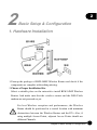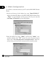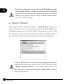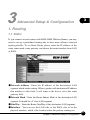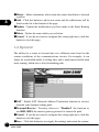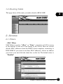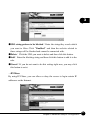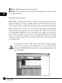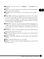
1
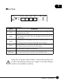
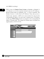
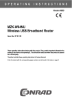
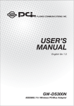
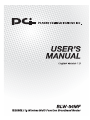
USER’S MANUAL IEEE802.11g Wireless Multi-Function Broadband Router BLW-54MF Foreword Explanation of the signals In order to let you set up and use this product correctly, please pay attention when reading or browsing the manual as you see these signals listed below. Warning/ Danger Users should read the explanation carefully and understand it completely, otherwise users might be in danger or even be injured. Caution/ Be Careful Remind users to be careful when setting up the product and to avoid damaging the product or its system programs. Seeking for service or searching for an agent or a distributor Thank you for purchasing products from Planex Communications Inc. If you have any operational problems while conÀguring or setting up the product, you may contact with our Customer Service Department or ask the agent or the distributor from which you bought the product for help. Moreover, during warranty, if you Ànd any defect or breakdown of the product, you may bring the product, assembly, and its warranty card to our company or to where you bought the product to ask for repair. ŘEvery product has different warranty period and contract; please refer to our company for further information or consult the agent or the distributor. Planex Communications Inc. Support PhoneĈ+65-6338-1704 (Singapore) +886-2-8218-7114 or +886-2-2219-7454 (Taiwan) Customer Service E-MailĈ[email protected] Contact Us TelĈ+886-2-2219-1816 FaxĈ+886-2-2219-0655 Agents & DistributorsĈhttp://www.planex.net/where/index.htm Trademarks: All trade names and trademarks are the properties of their respective companies. Copyright © 2006, All Rights Reserved. Contents Foreword Chapter 1 Introduction . . . . . . . . . . . . . . . . . . . . . . . . . . . . . 1 1. Package Contents . . . . . . . . . . . . . . . . . . . . 1 2. Introduction to BLW-54MF . . . . . . . . . . . . . . . 2 3. Product Housing. . . . . . . . . . . . . . . . . . . . . . . 4 Chapter 2 Basic Setup & Configuration . . . . . . . . . . . . . . . 7 1. How to Set Up BLW-54MF . . . . . . . . . . . . . . . 7 2. Client’s Computer Setup . . . . . . . . . . . . . . . . 8 3. :HE&RQÀJXUDWLRQ . . . . . . . . . . . . . . . . . . . . 10 4. Setup Wizard . . . . . . . . . . . . . . . . . . . . . . . . . 12 4.1 Set Password. . . . . . . . . . . . . . . . . . . . . . . 13 4.2 Choose Time Zone. . . . . . . . . . . . . . . . . . 13 4.3 Set LAN & DHCP Server . . . . . . . . . . . . . . 14 4.4 Select Internet Connection Type. . . . . . 15 4.5 Set Wireless Connection . . . . . . . . . . . . . 19 4.6 Setup Completed . . . . . . . . . . . . . . . . . . 19 5. Main. . . . . . . . . . . . . . . . . . . . . . . . . . . . . . . . . 21 5.1 LAN & DHCPServer. . . . . . . . . . . . . . . . . . 21 5.2 WAN. . . . . . . . . . . . . . . . . . . . . . . . . . . . . . 22 5.3 Password . . . . . . . . . . . . . . . . . . . . . . . . . . 30 5.4 Time . . . . . . . . . . . . . . . . . . . . . . . . . . . . . . 31 5.5 Dynamic DNS . . . . . . . . . . . . . . . . . . . . . . 32 6. Wireless . . . . . . . . . . . . . . . . . . . . . . . . . . . . . . 32 6.1 Basic . . . . . . . . . . . . . . . . . . . . . . . . . . . . . 32 6.2 Authentication . . . . . . . . . . . . . . . . . . . . . 34 6.3 Advanced . . . . . . . . . . . . . . . . . . . . . . . . 39 BLW-54MF 7. Status . . . . . . . . . . . . . . . . . . . . . . . . . . . . . . . . 41 7.1 Device Information . . . . . . . . . . . . . . . . . 41 7.2 Log. . . . . . . . . . . . . . . . . . . . . . . . . . . . . . . 42 7.3 Log Setting . . . . . . . . . . . . . . . . . . . . . . . . 43 7.4 Statistics. . . . . . . . . . . . . . . . . . . . . . . . . . . 44 7.5 Wireless . . . . . . . . . . . . . . . . . . . . . . . . . . . 44 Chapter 3 Advanced Setup & Configuration . . . . . . . . . . 45 1. Routing . . . . . . . . . . . . . . . . . . . . . . . . . . . . . . 45 1.1 Static . . . . . . . . . . . . . . . . . . . . . . . . . . . . . 45 1.2 Dynamic . . . . . . . . . . . . . . . . . . . . . . . . . . 46 1.3 Routing Table . . . . . . . . . . . . . . . . . . . . . . 47 2. Access. . . . . . . . . . . . . . . . . . . . . . . . . . . . . . . 47 2.1 Filters . . . . . . . . . . . . . . . . . . . . . . . . . . . . . 47 2.2 Virtual Server. . . . . . . . . . . . . . . . . . . . . . . 52 2.3 Special AP (Application). . . . . . . . . . . . . 54 2.4 DMZ . . . . . . . . . . . . . . . . . . . . . . . . . . . . . . 55 2.5 Firewall Rules. . . . . . . . . . . . . . . . . . . . . . . 56 3. Management. . . . . . . . . . . . . . . . . . . . . . . . . 57 3.1 Settings . . . . . . . . . . . . . . . . . . . . . . . . . . . 57 3.2 Remote Management . . . . . . . . . . . . . . 66 3.3 Firmware . . . . . . . . . . . . . . . . . . . . . . . . . . 68 3.4 Restart . . . . . . . . . . . . . . . . . . . . . . . . . . . . 69 4. Tools . . . . . . . . . . . . . . . . . . . . . . . . . . . . . . . . . 69 4.1 Ping Test . . . . . . . . . . . . . . . . . . . . . . . . . . 69 4.2 DNS Lookup . . . . . . . . . . . . . . . . . . . . . . . 70 Chapter 4 AP Setup & Configuration. . . . . . . . . . . . . . . . . 71 BLW-54MF Contents 1 1 Introduction 1. Package Contents After purchasing BLW-54MF Wireless Router form a distributor or an agency, please open the package and check that all the components listed below are included. If there is any item missing or damaged, please contact with the distributor or the agency at once. œBLW-54MF œ2dBi Antenna œUserŅs Manual œUTP Cable œAC Adapter œWarranty Card If plug the AC adapter which includes in the product package into a socket with different voltage power supply, it will cause damage and that is not included in warranty. 1 Chapter 1 Introduction 1 2. Introduction to BLW-54MF Thank you for purchasing BLW-54MF IEEE802.11g Wireless Multifunction Broadband Router. This 802.11b/g wireless router is a multifunction device which provides (1) shared broadband Internet access for LAN users through 4-port switching hub, (2) WDS Bridge/Repeater function, and (3) unique EZ-GO function. Moreover, it has an external switch to switch between AP and Router function that makes BLW-54MF an easy-to-use broadband router. BLW-54MF has a built-in Web server, thus you can access its settings through Web browsers, such as IE, Netscape, Firefox, and so on. You can set up and configure the settings easily and completely, and enjoy the convenience instantly. The following chapters will introduce you the configuration steps and fantastic functions of BLW-54MF. With all these features, BLW-54MF Wireless Broadband Router must be the best solution for both beginners and advanced users. Special Features of BLW-54MF œSupport EZ-GOĞEazy Go to LinkğFunction Just press the button and then the wireless network will be connected and the authentication will be set up. ŏ BLW-54MF must collocate with the designated adapter GW-US54SG. œSupport AP/Router Switching Users can use the switch at the back of BLW-54MF to choose AP or Router mode to use. œSupport WDS, Repeater Extended the coverage of wireless network. 2 BLW-54MF 1 œSupport Wireless Authentication BLW-54MF supports 64/128 Bit WEP, WPA, WPA AUTO, WPA-PSK/ EAP and WPA2-PSK/EAP which can prevent others from stealing your bandwidth and avoid information leak. œSupport Anti-DoS Function SPI Anti-DoS Firewall can prevent hacker's invasion. œSupport Virtual Server & DMZ Virtual server and DMZ functions can let BLW-54MF access LAN service through Internet. œSupport English/Chinese Language Switching Function Configuration page of BLW-54MF can auto-select languages depending on Windows O.S. System Requirements œWindows, Macintosh, or Linux-based Operating System with an installed Ethernet adapter. œInternet Explorer 6.x above, Netscape Navigator 6.x above, or other web browsers with JavaScript function. œNetwork cables. Use standard 10/100BaseT network (UTP) cables with RJ45 connectors. œTCP/IP protocol must be installed on all PCs. 3 Chapter 1 Introduction 1 3. Product Housing ŜFront Panel LEDs Status Meaning Power On/Off When starting up BLW-54MF, the Power LED will be on. Blinking Press the EZ-GO button at the back of BLW-54MF and enable EZ-GO function. After pressing EZ-GO button, the LED will be blinking for 5 minutes that means GWUS54SG can search for BLW-54MF and connect with it. Status EZ-GO If BLW-54MF has connected with GW-US54SG successfully, EZ-GO LED will be on all the time. When the connection is established between BLW-54MF and a modem, the WAN LED will be on. And the WAN On/Off/Blinking LED will be blinking when transmitting or receiving data via WAN port. When the power is on, the LAN LED will be on all the On/Off/Blinking time. If it is transmitting data, the LAN LED will be blinking. On WAN LAN When BLW-54MF Ànds any available wireless connection, the wireless LED will be on. And the LED will be Wireless On/Off/Blinking blinking when transmitting or receiving data via wireless connection. AP mode 4 BLW-54MF On/Off When switch to AP mode, the AP mode LED will be on all the time; if it has not been switched to AP mode, the LED will be off. 1 ŜRear Panel Ports Function AC Plug the power cord into this port and the other side of the adaptor should be plugged into the socket. WAN Connect a DSL or Cable Modem to the WAN port and link to the internet. If your modem came with a cable, use the supplied cable. Otherwise, use a standard cable. LAN Use standard LAN cables (RJ45 connectors) to connect your PCs to these ports. Any LAN port can be connected with another hub, if required. Reset Press the button for 3-5 seconds and then release it. BLW-54MF will automatically restart and back to the default settings. Status EZ-GO Press this button to enable EZ-GO function. AP/Router Users can use this switch to manually switch AP/Router mode. If plug the AC adapter which includes in the product package into a socket with different voltage power supply, it will cause damage and that is not included in warranty. 5 Chapter 1 Introduction 2 2 Basic Setup & Configuration 1. Hardware Installation 1.Unwrap the package of BLW-54MF Wireless Router and check if the components are complete with nothing missing. 2.Choose a Proper Installation Site. Select a suitable place on the network to install BLW-54MF Wireless Router. And make sure that the wireless router and the DSL/Cable modem are not powered on yet. For best Wireless reception and performance, the Wireless Router should be positioned in a central location with minimum obstructions between the Wireless Router and the PCs. Also, if using multiple Access Points, adjacent Access Points should use different Channels. 7 Chapter 2 Basic Setup & Configuration 2 3.Connect LAN Cables. Use standard LAN cables (RJ-45) to connect PCs to the switching hub ports on BLW-54MF. Both 10 Base-T and 100 Base-T connections can be used simultaneously. 4.Connect WAN Cable. Connect the DSL or Cable modem to the WAN port on BLW-54MF. 5.Power On. Power the DSL or Cable modem on. At last, connect the adapter with BLW-54MF and plug the other side of the power cord into the power socket. Power BLW-54MF Wireless Router on. While detecting, the Power LED will be on and then the BLW-54MF will be ready in a short time. 2. Client's Computer Setup The computers on your LAN need to be set up to cooperate with BLW54MF Wireless Router. Please make sure that your operating system already enabled your interface card on the host and connected to one of the LAN ports on BLW-54MF through CAT-5 cable. Be sure that LEDs on BLW-54MF are already on and the LED corresponds with the port which you connected. If you switch on BLW-54MF for the first time, owing to the default status, it will automatically enable the embedded DHCP server and start to distribute IP to your host. In addition, the default IP address of BLW-54MF is ņ192.168.1.1.ŇIf your operating system is Windows 98/2000/XP, you may be able to use command ofņipconfigŇto inquire whether you have the correct IP address or not. If you are using Linux/Unix-Like system, you can useņifconfigŇto check your NIC (Network Interface Card) address. The instructions are as follows: œWindows98 1.ClickņStartƖProgramsƖMS-DOSŇorņStartƖRunĀŇand type inņcommand.exeŇand then press enter. 8 BLW-54MF 2.ņMS-DOSŇwindow will appear. 3.TypeņipconfigŇafter the command ofņc:>Ňand then press enter. 2 4.MS-DOS will appear your NIC address in the window, please take notice of the value ofņIP AddressŇandņDefault Gateway.Ň 5.The value ofņDefault GatewayŇis the IP address of BLW-54MF. œWindows2000/XP 1.Please make sure that you do have the authority to access as an ņAdministratorŇor you are already one of theņSystem Administrators.Ň 2.ClickņStartƖProgramsƖAccessoriesƖCommand PromptŇor ņStartƖRunĀ,Ňand then type inņcmd.exeŇand press enter. 3.It will appear aņMS-DOSŇwindow. 4.TypeņipconfigŇafter the command ofņc:>Ňand then press enter. 5.MS-DOS will appear your NIC address in the window, please take notice of the value ofņIP AddressŇandņDefault Gateway.Ň 6.The value ofņDefault GatewayŇis the IP address of BLW-54MF. œLinux / Unix-Like 1.At first please make sure that your NIC are already enabled and works properly. 2.And be sure you haveņrootŇnumber or your already are one of the members of aņrootŇgroup. 3.Please typeņifconfigŇofņifconfig -aŇafterņ#Ňand then press enter. 4.It will appear your present NIC address in the window, please take notice of the value ofņIP AddressŇandņGateway.Ň 5.The value ofņGatewayŇis the IP address of BLW-54MF. If you can getņIP AddressŇandņGateway,Ň normally, it means that you may use web browser to configure BLW-54MF. Type your destination ęņhttp://192.168.1.1Ň (default IP Address of BLW-54MF) on the Address Bar in the web browser. If you have changed the default IP Address of BLW-54MF, please type in the new address on the address bar. 9 Chapter 2 Basic Setup & Configuration 2 3. Web Configuration To establish a connection between your PC and the BLW-54MF Wireless Router: 1.Star the web browser. In the Address box, enterņhttp://192.168.1.1Ň which is the default IP Address of the BLW-54MF Wireless Router. Press ņEnterŇon your keyboard, and the pop-up will ask you to enter the User Name and Password to get into the program. 2.Enter the default User NameņadminŇand PasswordņadminŇ(casesensitive) and then clickņOKŇto enter the system. You can also put a check in theņSave this password in your password listŇcheck box, and next time you do not need to enter password to enter the system. 10 BLW-54MF 3.After entering the system, BLW-54MF will show you the Main page. During configuration, you can use the tabs on the top of the page and 2 menu at the left side of the page to navigate. Besides, it is necessary that, after configuring, you should clickņApplyŇto enable the settings you have made. If your BLW-54MF Wireless Router does not response, and you cannot enter the web configuration page, please follow the steps below to check if there is any problem: 1.Make sure that BLW-54MF Wireless Router is properly installed and powered on, and LAN connection is O.K. You can test the connection by usingņPingŇcommand: ŚOpen MS-DOS window or clickņStartƖRunĀŇon the desktop to show the command prompt window. ŚEnter the command: ping 192.168.1.1 ŚIf it shows the message ofņRequest time out,Ňthe problem can be either disorder of connection, or the conflict between your PC's IP address and the routerŅs IP address. 2.If your PC uses static IP address, the IP address must between in the range of 192.168.1.2~192.168.1.254, in order not to occupy the BLW-54MFŅs default IP addressņ192.168.1.1.Ň In addition, the subnet mask must beņ255.255.255.0.ŇTo know more details of your PC and Internet connection, please check the TCP/IP settings on your PC. 11 Chapter 2 Basic Setup & Configuration 3.You have to make sure that your PC and BLW-54MF are on the same segment. Besides, you have to use the wired LAN interface 2 when first accessing the web configuration page, the wireless interface only works when the settings of BLW-54MF matches your PC's wireless settings. 4. Setup Wizard After logging in the configuration page, aņSetup WizardŇdialog box pops up. You may choose to use setup wizard to set up BLW-54MF or use configuration page to set up all the settings. You may use wizard to help you complete setting up and start connect with Internet through simply a few steps. Please follow the instructions below to do the configuration. If you do NOT want to see setup wizard popping up whenever you open the main page, please clickņNoŇafter the words ņdisplay wizard next time?Ňon the setup wizard window. And when next time you enter the main page of BLW-54MF, it will not activate setup wizard. 12 BLW-54MF 4.1 Set Password 2 Step 1ĈThe default User Name of BLW-54MF Wireless Router isņ adminŇand Password isņadmin.ŇIt is recommended that you should change the default password to have better protection over the router and the LAN. You must memorize the password set by you to enter the system; otherwise, you have to restore the whole systems and then configure the settings again. Please enter your new password twice on the following page and then clickņNextŇto keep on setting up. 4.2 Choose Time Zone Step 2ĈYou can set the system time according to the time zone where you locate now. You may scroll down the list to find a suitable time zone. 13 Chapter 2 Basic Setup & Configuration 2 4.3 Set LAN & DHCP Server Step 3ĈYou can do LAN port configuration and enable/disable DHCP server through this page. œLAN IP AddressĈHere is the IP address of the LAN side of BLW54MF. The default IP address isņ192.168.1.1Ň. œLAN Subnet MaskĈThe Subnet Mask of the LAN side of BLW-54MF isņ255.255.255.0Ň. œDHCP ServerĈDHCP stands for Dynamic Host Control Protocol. BLW-54MF Wireless Broadband Router has a built-in DHCP server which can automatically assign an IP address to those computers on the LAN/private network. Click to enable/disable DHCP server. œRange StartĈThe first IP address which DHCP server of BLW-54MF starts to distribute. œRange EndĈThe last IP address which DHCP server of BLW-54MF distributes. œNextĈClick this button to save the settings and go to next page. 14 BLW-54MF 4.4 Select Internet Connection Type 2 Step 4ĈThe followings are the most common used connection types: Obtain IP automatically (DHCP client), Fixed IP address, and PPPoE. If you want to know more about the other types of WAN configurations, please refer toņMainŇconfiguration page. After auto-detecting WAN, the setup wizard might skip the page of ņSelect Internet Connection TypeŇpage and directly shows the detected connection type. If BLW-54MF shows the connection mode which you do not want to use, clickņBackŇto the previous page to select the Internet connection type. ƖObtian IP automatically (DHCP client) 1.If you use cable modem, or you are a DHCP client, you may choose this entry and use the wizard to configure. 15 Chapter 2 Basic Setup & Configuration 2 2.The following are the WAN settings; please configure the settings according to the real environment. œHost NameĈYou may follow the demands of your ISP, if needed, you may fill in the designated host name. œMACĈThe default MAC address of BLW-54MF is the Network Interface CardŅs (NIC) MAC address on the WAN side. If you were asked to use the NIC provided by the ISP, you may clickņClone MAC AddressŇand use the MAC address of NIC provided by the ISP. We do not suggest you to change the default MAC address, if your ISP does not ask you to change it.Ą œNextĈClick this button to save the settings and go to next page. ƖFixed IP address 1.If you have already had a Static IP address, you can choose this entry and use the wizard to configure. 16 BLW-54MF 2.The following are the WAN settings; please configure the settings according to the real environment. 2 œWAN IP AddressĈEnter the IP address provided by your ISP. œWAN Subnet MaskĈEnter the Subnet Mask address provided by your ISP. œWAN Gateway AddressĈEnter the Default Gateway address provided by your ISP. œDNS Server Address 1~3ĈEnter the DNS IP address provided by your ISP. œNextĈClick this button to save the settings and go to next page. ƖPPPoE 1.If you use PPPoE, you may choose this entry and use the wizard to configure. 17 Chapter 2 Basic Setup & Configuration 2 2.The following are the WAN settings; please configure the settings according to the real environment. œObtain IP Automatically/Specify IPĈChoose a mode according to the service provided by your ISP. œUser NameĈPlease enter the User Name/Account provided by your ISP. (case-sensitive) œPasswordĈPlease enter the Password provided by your ISP. (casesensitive) œVerify PasswordĈEnter the Password again to be verified. œIP AddressĈPlease enter the information provided by your ISP. œService NameĈIf your ISP provides you service name, please enter the name according to the provided information. œNextĈClick this button to save the settings and go to next page. 18 BLW-54MF 4.5 Set Wireless Connection 2 Step 5ĈChoose if you want to use wireless connection. œWirelessĈYou may choose if you want to enable wireless function to let users connect with BLW-54MF through wireless network. œSSIDĈEvery SSID is unique in the WLAN (SSID can be 16-digit ASCII characters and case-sensitive). SSID can prevent two nearby WLAN from combining to be one. You can give BLW-54MF an SSID, and only whose SSID is the same with it can connect with it. œChannelĈĈHere shows the channels provided by the local wireless connection. The setting of the channels of the wireless network should be the same as the wireless APs. œNextĈClick this button to save the settings and go to next page. 4.6 Setup Completed Step 6ĈAfter completing the five steps above, please clickņRestartŇ to save all the settings and restart the system. When restarting the system, please do not close the window or unplug the power cord. The system will ask you to clickņCloseŇto go back to the homepage and show the latest system status after restarting. 19 Chapter 2 Basic Setup & Configuration 2 20 BLW-54MF 5. Main 2 The Main page of BLW-54MF can let users configure the basic settings related to network connection. These settings also appear in the Setup Wizard. If you want to modify some of the details, you do not need to enter Setup Wizard, but configure the settings through the Main page. 5.1 LAN & DHCP Server This page shows if the LAN settings and the DHCP server are enabled or not. The bottom of the page shows the device which is connecting with BLW-54MF. œHost NameĈYou may follow the request of your ISP, and enter the designated Host Name, if needed. œIP AddressĈEnter the LAN address of BLW-54M. The default LAN IP address isņ192.168.1.1Ň. œSubnet MaskĈThe default Subnet Mask of the LAN side of BLW54MF isņ255.255.255.0Ň. œDHCP ServerĈChoose if you want to enable the embedded DHCP Server of BLW-54MF. œRange StartĈThe first IP address which DHCP server of BLW-54MF starts to distribute. 21 Chapter 2 Basic Setup & Configuration 2 œRange EndĈThe last IP address which DHCP server of BLW-54MF distributes. œDomain NameĈIf you had applied a Domain Name, you may enter it here. œLease TimeĈDHCP server can let a PC get the same IP address whenever it starts up on the LAN. You can distribute an appointed IP address to a specific computer according to the PC's MAC address and also set a period of time of leasing IP. œCancelĈIf you do not want to configure this setting right now, click this button to exist this page. œSaveĈClick this button to save/apply the settings and restart the system. 5.2 WAN In the WAN settings, BLW-54MF Wireless Router provides many kinds of access. You can configure the WAN side according to the real environment. ƖDHCP Client or Fixed IP œWAN IP AddressĈPlease choose the service provided by your ISP. œIP AddressĈEnter the IP address provided by your ISP. œSubnet MaskĈEnter the Subnet Mask address provided by your ISP. 22 BLW-54MF œGateWayĈEnter the default Gateway address provided by your ISP. œDNS 1~3ĈEnter the DNS IP address provided by your ISP. 2 œMAC AddressĈThe default MAC address of BLW-54MF is the Network Interface Card's (NIC) MAC address on the WAN side. If you were asked to use the NIC provided by the ISP, you may clickņClone MAC AddressŇand enter the MAC address of NIC provided by the ISP. We do not suggest you to change the default MAC address, if your ISP does not ask you to change it. œCancelĈIf you do not want to configure this setting right now, click this button to exist this page. œApplyĈClick this button to save/apply the settings and restart the system. ƖPPPoE œWAN IP AddressĈPlease choose the service provided by your ISP. œService Name(optional)ĈIf your ISP provides you Service Name, please enter the provided information. œUser NameĈPlease enter the User Name/Account provided by your ISP. (case-sensitive) œPasswordĈPlease enter the Password provided by your ISP. (casesensitive) 23 Chapter 2 Basic Setup & Configuration 2 œVerify PasswordĈPlease enter the Password again. œDNS 1~3ĈYou may enter the first, second, and third DNS Server provided by your ISP. œAuto-reconnectĈWhen BLW-54MF disconnects with your xDSL service, you can chose to reconnect online automatically, manually or connect-on-demand. If you chooseņAlways-OnŇ, BLW-54MF Wireless Router will automatically reconnect to your ISP when you restart the system or the connection is stopped.ņManualŇmeans you have to reconnect through your own configuration.ņConnect-OnDemandŇ means when there is a need (e.g. open a web browser), and then the system may reconnect. œIdle Time OutĈIdle Time Out means a period of idle time before you go offline. Enter a maximum period of time (minutes) to define the maximum idle time. If the idle time is above the defined maximum idle time, it will go offline immediately. You can set the value to be 0 or Auto Reconnect to disable this function. œMTUĈMTU means Maximum Transmission Unit, the largest physical packet size, measured in bytes, which a network can transmit. The default value is 1492. Please set up the MTU according to your system environment. Only enter a new MTU when your ISP requires, otherwise, please leave it as the default setting. When using PPPoE connection, you may need to change MTU settings to maintain the connection with your ISP, however, if the incorrect value was entered, you may be unable to access certain websites. Reducing the packet size can help connecting to certain websites or speeding up the transmission rate. œCancelĈIf you do not want to configure this setting right now, click this button to exist this page. œApplyĈClick this button to save/apply the settings and restart the system. 24 BLW-54MF ƖPPTP Point-to-Point Tunneling Protocol (PPTP), a protocol that allows 2 corporations to extend their own corporate network through private "tunnels" over the public Internet. Effectively, a corporation uses a widearea network as a single large local area network. A company no longer needs to lease its own lines for wide-area communication but can securely use the public networks. This kind of interconnection is known as a virtual private network (VPN) œWAN IP AddressĈPlease choose the service provided by your ISP. œIP AddressĈEnter the IP address provided by your ISP. œSubnet MaskĈEnter the Subnet Mask address provided by your ISP. œGateWayĈEnter the default Gateway address provided by your ISP. œDNS 1~3ĈΞYou may enter the first, second, and third DNS Server provided by your ISP. œServer IP/NameĈPlease enter the VPN Server IP and its Name. œPPTP AccountĈPlease enter your PPTP Account number. œPPTP PasswordĈPlease enter the Password collocated with your PPTP Account. œVerify PasswordĈEnter your Password again for verification. 25 Chapter 2 Basic Setup & Configuration 2 œAuto-reconnectĈWhen BLW-54MF disconnects with your xDSL service, you can chose to reconnect online automatically, manually or connect-on-demand. If you chooseņAlways-OnŇ, BLW-54MF Wireless Router will automatically reconnect to your ISP when you restart the system or the connection is stopped.ņManualŇmeans you have to reconnect through your own configuration.ņConnect-OnDemandŇ means when there is a need (e.g. open a web browser), and then the system may reconnect. œIdle Time OutĈIdle Time Out means a period of idle time before you go offline. Enter a maximum period of time (minutes) to define the maximum idle time. If the idle time is above the defined maximum idle time, it will go offline immediately. You can set the value to be 0 or Auto Reconnect to disable this function. œMTUĈMTU means Maximum Transmission Unit, the largest physical packet size, measured in bytes, which a network can transmit. The default value is 1400. Please set up the MTU according to your system environment. Only enter a new MTU when your ISP requires, otherwise, please leave it as the default setting. When using PPPoE connection, you may need to change MTU settings to maintain the connection with your ISP, however, if the incorrect value was entered, you may be unable to access certain websites. Reducing the packet size can help connecting to certain websites or speeding up the transmission rate. œCancelĈIf you do not want to configure this setting right now, click this button to exist this page. œApplyĈClick this button to save/apply the settings and restart the system. 26 BLW-54MF ƖL2TP Layer 2 Tunneling Protocol (L2TP) is a tunneling protocol used to 2 support virtual private network. L2TP is original from CisicoŅs Layer 2 Forwarding (L2F) and MicrosoftŅs Point-to-Point Tunneling Protocol (PPTP). L2TP provides additional security features other than PPTP. L2TP acts as data link layer protocaol for tunneling network traffic between clients and VPN server over an Internet. It builds up Point-to-Point Protocol (PPP) sessions within an L2TP tunnel. œWAN IP AddressĈPlease choose the service provided by your ISP. œIP AddressĈEnter the IP address provided by your ISP. œSubnet MaskĈEnter the Subnet Mask address provided by your ISP. œGateWayĈEnter the default Gateway address provided by your ISP. œDNS 1~3ĈΞYou may enter the first, second, and third DNS Server provided by your ISP. œServer IP/NameĈPlease enter the VPN Server IP and its Name. œL2TP AccountĈPlease enter your L2TP Account number. œL2TP PasswordĈPlease enter the Password collocated with your L2TP Account. œVerify PasswordĈEnter your Password again for verification. 27 Chapter 2 Basic Setup & Configuration 2 œAuto-reconnectĈWhen BLW-54MF disconnects with your xDSL service, you can chose to reconnect online automatically, manually or connect-on-demand. If you chooseņAlways-OnŇ, BLW-54MF Wireless Router will automatically reconnect to your ISP when you restart the system or the connection is stopped.ņManualŇmeans you have to reconnect through your own configuration.ņConnect-OnDemandŇ means when there is a need (e.g. open a web browser), and then the system may reconnect. œIdle Time OutĈIdle Time Out means a period of idle time before you go offline. Enter a maximum period of time (minutes) to define the maximum idle time. If the idle time is above the defined maximum idle time, it will go offline immediately. You can set the value to be 0 or Auto Reconnect to disable this function. œMTUĈMTU means Maximum Transmission Unit, the largest physical packet size, measured in bytes, which a network can transmit. The default value is 1400. Please set up the MTU according to your system environment. Only enter a new MTU when your ISP requires, otherwise, please leave it as the default setting. When using PPPoE connection, you may need to change MTU settings to maintain the connection with your ISP, however, if the incorrect value was entered, you may be unable to access certain websites. Reducing the packet size can help connecting to certain websites or speeding up the transmission rate. œCancelĈIf you do not want to configure this setting right now, click this button to exist this page. œApplyĈClick this button to save/apply the settings and restart the system. 28 BLW-54MF ƖBigPond Cable Telstra Bigpond is the largest ISP in Australia, so the BigPond Cable is 2 mainly used in Australia. œUser NameĈPlease enter the User Name/Account provided by your ISP. (case-sensitive) œPasswordĈPlease enter the Password provided by your ISP. (casesensitive) œVerify PasswordĈPlease enter the Password again. œServer IP/NameĈPlease enter the Server IP and its Name provided by the ISP. (optional) œAuth ServerĈPlease scroll down the list to select the authentication server you use. œMAC AddressĈThe default MAC address of BLW-54MF is the Network Interface Card's (NIC) MAC address on the WAN side. If you were asked to use the NIC provided by the ISP, you may clickņClone MAC AddressŇand enter the MAC address of NIC provided by the ISP. We do not suggest you to change the default MAC address, if your ISP does not ask you to change it. œCancelĈIf you do not want to configure this setting right now, click this button to exist this page. œApplyĈClick this button to save/apply the settings and restart the system. 29 Chapter 2 Basic Setup & Configuration 2 5.3 Password The default User Name of BLW-54MF Wireless Router isņadminŇ and Password isņadmin.ŇIt is recommended that you should change the default password to have better protection over the router and the LAN. You must memorize the password set by you to enter the system; otherwise, you have to restore the whole systems and then configure the settings again. œAdministratorĈEnter the Password for the Administrator. (Enter 15 alphanumeric characters at most.) œUserĈEnter the Password collocated with the User account. (Enter 15 alphanumeric characters at most.) The default user password is null/no password which means users just need to enterņuserŇfor the account, and do not need to enter password to get in. œConfirm PasswordĈEnter the Password again for verification. œCancelĈIf you do not want to configure this setting right now, click this button to exist this page. œApplyĈClick this button to save/apply the settings and restart the system. In this manual,ņUserŇrefers to people who can use BLW54MF Wireless Broadband Router. AndņAdministratorŇmeans someone who can configure BLW-54MF Wireless Broadband Router and can provide limits of authority to others. 30 BLW-54MF 5.4 Time 2 You can set the system time according to the time zone where you locate now. œLocal TimeĈIf you synchronize with NTP Server or manually set up the time, you may see the local time here. œTime ZoneĈScroll the list to choose the time zone for BLW-54MF. œSynchronize the clock withĈYou can chooseņAutomaticŇto let system use NTP to synchronize with the system, or chooseņManualŇ and enter your local time by your own. œDefault NTP ServerĈScroll down the list to select a NTP Server to let system synchronize with. œSet the timeĈIf you chooseņManualŇset up the time, you may configure the local time here. œSet TimeĈClick this button and the system will synchronize with the time you set. œDaylight SavingĈIf the time zone you are in now is using daylight saving, please enable this function and set a period of time for daylight saving. œCancelĈIf you do not want to configure this setting right now, click this button to exist this page. œApplyĈClick this button; the system will synchronize with the NTP Server and save the settings. 31 Chapter 2 Basic Setup & Configuration 2 5.5 Dynamic DNS Dynamic DNS can let you connect with one or more DDNS services to update your current dynamic IP address. œDDNSĈYou can enable this function and scroll the list to choose the DDNS service which you want to use. œServer AddressĈThere are three server addresses you can choose from: DynDns.org, EasyDns.com, and No-IP.com. œHost NameĈEnter the Host Name which you registered. œUser NameĈEnter the User Name which you use to login your account. (case-sensitive) œPasswordĈEnter the Password which you use to login your account. (case-sensitive) œCancelĈIf you do not want to configure this setting right now, click this button to exist this page. œApplyĈClick this button to save/apply the settings and restart the system. 6. Wireless 6.1 Basic This page includes all the fundamental and basic parameters. After changing any parameters, you have to apply and restart the device and then the new settings can be effective. 32 BLW-54MF 2 œWirelessĈClickņEnabledŇand start to set up the Wireless LAN Interface and start using wireless network. œWireless ModeĈThere are two wireless rate mode: 802.11 b/g, and 802.11 b. œSSIDĈEvery SSID is unique in the WLAN (SSID can be 16-digit ASCII characters and case-sensitive). SSID can prevent two nearby WLAN from combining to be one. You can give BLW-54MF an SSID, and only whose SSID is the same with it can connect with it. œRegionĈScroll down the list to choose a region for collocating with the appropriate channels. œChannelĈHere shows the channels provided by the local wireless connection. The setting of the channels of the wireless network should be the same as the wireless APs. œExtended Range ModeĈChooseņEnabledŇand start to use wireless XR (eXtended Range) mode which can enhance the wireless coverage of BLW-54MF. œSSID BroadcastĈIf you want to let other users to find you on the LAN, you may chooseņEnabledŇto start SSID Broadcast, yet you should enter a Network Name (SSID) before enabling this function; otherwise, you can chooseņDisabled.Ň œWDSĈEnabling the WDS function can let BLW-54MF Wireless Router connect with other specific WDS AP through wireless interface. If two wireless AP need to connect with each other, they can use BLW-54MF as the Repeater or as the Bridge to bridge the other two APs. There are three modes: Disabled, Repeater, and Bridge. Please choose a proper mode according to the real environment. 33 Chapter 2 Basic Setup & Configuration 2 œCancelĈIf you do not want to configure this setting right now, click this button to exist this page. œApplyĈClick this button to save/apply the settings and restart the system. 6.2 Authentication In this page, you can configure the security of your wireless network. Selecting different method can make different levels of security. However, no matter what kind of authentication or encryption you use to prevent data packets from being eavesdropped by people without authentication, it may cause decrease of the data throughput of the wireless connection. Authentication There are four kinds of authentication of BLW-54MF Wireless Router: WEP, WPA, WPA2, and WPA-AUTO (PSK). After selecting the authentication mode, it has to cooperate with the encryption type. The settings of authentication on the destination network must be the same with BLW-54MF. ƖWEP WEP is short for Wired Equivalent Privacy, a security protocol for WLANs defined in the 802.11b standard. WEP is designed to provide the same level of security as that of a wired LAN. WEP aims to provide security by encrypting data over radio waves so that it is protected as it transmitted from one end point to another. There are two kinds of WEP encryption: 64 bit and 128 bit. 64 bit needs 10 hex characters to be the key and 128 bit needs 26 hex characters. 34 BLW-54MF œWEPĈOpen System – It does not need authentication when connecting to the AP. Shared Key –Only wireless adapters using a 2 shared key (WEP Key identified) are allowed to connecting to the AP. œModeĈHEX – OnlyņA~F,Ňņa~f,Ňandņ0~9Ňare allowed to be set in a WEP key. ASCII –Numerical values, characters or signs are all allowed to be arranged into a WEP key. It is more recognizable for user. œWEP KeyĈ64-bit –Enter 10-digit Hex values or 5-digit ASCII values as the encryption keys. For example:ņ0123456aefŇorņGuest.Ň 128-bit –Enter 26-digit Hex values or 13-digit ASCII values as the encryption keys. For example:ņ01234567890123456789abcdefŇorņ administrator.Ň œKey1~4ĈThis setting only takes effect underņWEPŇandņSharedŇ mode. There are four types of WEP key settings, please set the key depending on the real environment. œCancelĈIf you do not want to configure this setting right now, click this button to exist this page. œApplyĈClick this button to save/apply the settings and restart the system. ƖWPA WPA is short for Wi-Fi Protected Access. It was designed to improve upon the security features of WEP. The technology is designed to work with existing Wi-Fi products that have been enabled with WEP. Through the data encryption, access control and authentication, it provides better protection over data transmission. WPA uses 128-digit keys to ensure the wireless network privacy and security. 35 Chapter 2 Basic Setup & Configuration 2 ƖWPA2 WPA2 is short for Wi-Fi Protected Access 2. It is the follow on security method to WPA for wireless networks that provides stronger data protection and network access control. It provides enterprise and consumer Wi-Fi users with a high level of assurance that only authorized users can access their wireless networks. There are two versions of WPA2: WPA2Personal, and WPA2- Enterprise. WPA2-Personal protects unauthorized network access by utilizing a set-up password. WPA2-Enterprise verifies network users through a server. WPA2 is backward compatible with WPA. 36 BLW-54MF 2 ƖWPA-AUTO WPA-PSK is short for Wi-Fi Protected Access-Pre-Shared Key. WPA-PSK uses the same encryption way with WPA, and the only difference between them is that WPA-PSK recreates a simple shared key, instead of using the userŅs certification. 37 Chapter 2 Basic Setup & Configuration 2 œPSK/EAPĈPSK – Short for Pre-shared Key. It is the use of secret passwords or encryption keys that are entered into both sides of the message exchange ahead of time. Pre-shared keys (PSK) are typed into the clients and servers (authentication servers, access points, etc.) or entered via floppy, CD-ROM or smart card. Contrast with "serverbased keys," in which one side generates a key and sends it to the other side during the authentication session. EAP – Short for Extensible Authentication Protocol. A protocol that acts as a framework and transport for other authentication protocols. EAP uses its own start and end messages, but then carries any number of third-party messages between the client (supplicant) and access control node such as an access point in a wireless network. œCipher TypeĈTKIP –It is short for Temporal Key Integrity Protocol. TKIP scrambles the key using a hashing algorithm and, by adding an integrity-checking feature, ensures that the keys havenŅt been tampered with. AES – Short for Advanced Encryption Standard, a symmetric 128-bit block data encryption technique. It works at multiple network layers simultaneously and has a fixed block size of 128-bits and a key size of 128, 192, or 256-bits. œPassphraseĈPassphrase (also called a shared secret) that must be entered in both the wireless access point and the WPA clients (computers). The WPA pre-shared key should be a random sequence of either keyboard characters (upper and lowercase letters, numbers, and punctuation). You have to enter the same Passphrase or Hexadecimal key into both your access points and computers but the length requirement is changed. The more random your WPA pre-shared key, the safer it is to use. œConfirmed PassphraseĈPlease enter the Passphrase you just key in again for confirmation. œRADIUS ServerĈRADIUS is short for Remote Authentication Dial-In User Service, an authentication and accounting system used by 38 BLW-54MF many Internet Service Providers (ISPs). RADIUS setup is used to set up additional parameters for authorizing wireless clients through RADIUS server. The RADIUS setup is required when you select to use WPA authentication. œCancelĈIf you do not want to configure this setting right now, click this button to exist this page. œApplyĈClick this button to save/apply the settings and restart the system. 2 6.3 Advanced œBeacon IntervalĈBeacon Interval is the amount of time between beacon transmissions. Before a station enters power save mode, the station needs the beacon interval to know when to start up again and receive the beacon. œRTS ThresholdĈHere you can define the minimum value of RTS (Request to Send) packets and preventņHidden NodesŇproblems. Please enter a value between 0~2346, and when the packets are bigger than the RTS value the function will start to work. œFragment ThresholdĈThis value can define the maximum packet sized, so the packets bigger than this size will be segmented. If you set the lower value, and found there is higher packets error value, you can set the value higher, however, that may decrease the whole performance of BLW-54MF. The default value is 2346, and you can set a value between 256~2346. 39 Chapter 2 Basic Setup & Configuration 2 œDTIMมĈѩᇴࣃܑĶਖ਼྿ྤफ़߹ϯੈिķ۞มॡมĄ DTIMҜߏ˘࣎ࣆᇴࢍॡҜĂΞ఼ۢϡ͗ბ˭˘้࣎ბ۞ ቤᇃᇫٕкࢦ็ᇫੈिॡĂιົͽDTIMมᇴࣃਖ਼˭˘࣎ DTIMĄAPϡ͗ბົܫזᇾ֭ۢᑕྍତќᇃᇫкࢦ็ᇫĄ œTX Rates (MBps)ĈThe transmission rate can be: Auto/1/2/5.5/11/6/9/12/ 18/24/36Mbps. When you chooseņAuto,Ň BLW-54MF will automatically find the proper transmission rate for you. If you choose higher transmission rate, the distance between the AP and the Wireless NIC must be closer. Besides, when the Wireless NIC is 802.11b type, the maximum transmission rate is 11Mbps. œ11g only modeĈClick to use only 802.11g mode. œAntenna transmit powerĈPlease manual choose the transmitting power for BLW-54MF. There are several levels to choose. The system default is full which means BLW-54MF has the maximum Tx Power on wireless network. œCancelĈIf you do not want to configure this setting right now, click this button to exist this page. œApplyĈClick this button to save/apply the settings and restart the system. 40 BLW-54MF 7. Status 2 7.1 Device Information After entering the system, you can clickņStatusŇon the left menu to check all the settings and firmware version. 41 Chapter 2 Basic Setup & Configuration 2 7.2 Log BLW-54MF Wireless Router can record various types of activities. System Log records every events happened on the BLW-54MF Wireless Router. These data are useful for troubleshooting. If BLW-54MF restarts, the logs will be deleted automatically. œClear LogĈClick this button to delete all the logs recorded from the system started till now. œRefreshĈClick this button to update the log status and check the latest status. 42 BLW-54MF 7.3 Log Setting 2 When the log generates, the system can send a warning e-mail to the appointed e-mail address. œSMTP ServerĈEnter the IP address of SMTP Server for mail delivery. œSent toĈEnter the correct E-Mail Address of the recipient. If there is any error occurring when connecting, the system will generate related log and send to this E-Mail address. If you want to send the email immediately, clickņEmail Log NowŇto send it right away. œSyslog ServerĈYou can send the Syslog to your Linux Server, just enter the remote IP address of your Linux Server. œLog TypeĈYou may choose the types of log you want to check: System Activity, Debug Information, Attacks, Dropped Packets, or Notice. œCancelĈIf you do not want to configure this setting right now, click this button to exist this page. œApplyĈClick this button to save/apply the settings and restart the system. 43 Chapter 2 Basic Setup & Configuration 2 7.4 Statistic ClickņStatisticsŇ, the page will display the transmitted and received results. œResetĈClick this button to reset all the statistics back to zero and start to calculate again. 7.5 Wireless You may see the information of the users which is connection with BLW54MF now, including Connected Time, MAC Address, and Mode. 44 BLW-54MF 3 Advanced Setup & Configuration 3 1. Routing 1.1 Static If you connect several routers with BLW-54MF Wireless Router, you may need to set up a predefined routing rule to have more effective network topology/traffic. To set Static Route, please enter the IP address of the route, route mask, route gateway, and choose the route interface from LAN or WAN. œNetwork AddressĈEnter the IP address of the destination LAN segment which needs routing. When a packet with destination IP address that matches to this field, it will route to the device set in the route gateway field. œNetwork MaskĈEnter the Route Subnet Mask of the destination LAN segment. It should be a C class LAN segment. œGateWayĈEnter the Route GateWay of the destination LAN segment. œInterfaceĈYou can use the LAN side or the WAN side to be the physical interface, which is the location where the packets sending out. 45 Chapter 3 Advanced Setup & Configuration 3 œMetricĈMetric determines which route the router should use to forward a packet. œAddĈClick this button to add a new route and the added route will be listed on the list at the bottom of the page. œUpdateĈUpdate the modification you have made to the Static Routing function. œDeleteĈDelete the route which you set before. œCancelĈIf you do not want to configure this setting right now, click this button to exist this page. 1.2 Dynamic The ability for a router to forward data via a different route based on the current conditions of the communications circuits. For example, it can adjust for overloaded traffic or failing lines and is much more flexible than static routing, which uses a fixed forwarding path. œNATĈEnable NAT (Network Address Translation) function to receive/ transmit your dynamic routing path. œTransmit/ReceiveĈYou may choose toņDisabledŇthe function or use RIP1, RIP2, the interior gateway protocol to choose the path. œCancelĈIf you do not want to configure this setting right now, click this button to exist this page. œSaveĈClick this button to save/apply the settings and restart the system. 46 BLW-54MF 1.3 Routing Table This page shows all the route you made related to BLW-54MF. 3 2. Access 2.1 Filters ƖMAC Filters MAC Filters is used toņAllowŇorņDenyŇcomputers on LAN to access to the Internet. In the list at the bottom of the screen, there are several default MAC addresses from the DHCP client computers connecting to BLW-54MF. If you want to use these MAC addresses, choose an address you want to use and click the check box on the list. The default status is ņDisabledŇ. 47 Chapter 3 Advanced Setup & Configuration œDisabledĈIf you do not need MAC address at the moment, you may choose this option. 3 œOnly allow computers with MAC address listed below to access the networkĈChoose this option to allow computers with MAC addresses listed below to access to the network and Internet. All the other computers will be denied to access to the network and Internet. œOnly deny computers with MAC address listed below to access the networkĈChoose this option to deny computers with MAC addresses listed below to access to the network and Internet. All the other computers will be allowed to access to the network and Internet. œNameĈYou can name the host which you want to configure. œMAC AddressĈEnter a user's MAC address which needs to be filtered. œAddĈEnter the blocking MAC address and then click this button to add it to the rule. œUpdateĈUpdate the modification you have made to the MAC Filter function. œDeleteĈClick the MAC address you want to delete from the list and then click this button. œCancelĈIf you do not want to do this setting right now, you may click this button to exist. ƖURL Blocking Use URL Blocking to prevent PCs from accessing websites including the following URL strings. Users can enter some key words such as adult, hacker or other related words to prevent PCs on the LAN from connecting with these websites. 48 BLW-54MF 3 œURL string pattern to be blockedĈEnter the strings/key words which you want to filter. ClickņEnabledŇand then the website related to these strings will be blocked and cannot be connected with. œDeleteĈClick the URL you want to delete and then click this button. œAddĈEnter the blocking string and then click this button to add it to the rule. œCancelĈIf you do not want to do this setting right now, you may click this button to exist. ƖIP Filters By using IP Filters, you can allow or deny the access to login certain IP addresses on the Internet. 49 Chapter 3 Advanced Setup & Configuration œEnabledĈClickņEnabledŇto apply IP filter, orņDisabledŇto apply it later. 3 œRange Start/Range EndĈType in a range of IP address to apply IP filtering on. If you only want to apply on a single computer, please enter the IP address of the computer in the beginning blank, and leave the ending part blank. œAddĈEnter the filter string and then click this button to add it to the rule. œUpdateĈUpdate the modification you have made to the IP Filter function. œDeleteĈDelete the IP filter string you set before. œCancelĈIf you do not want to do this setting right now, you may click this button to exist. ƖDomain Blocking To use Domain Blocking to allow or deny computers on the LAN to access to certain domains, no matter they are services under WWW, FTP, SMTP, and so on. You can have a maximum of 32 sets of domain names. œDisabledĈIf you do not want to use domain blocking function, you can choose this option. œAllow Users to access all domains exceptņBlocked DomainsŇĈ Choose this option to block users to access to certain Internet domains listed below, but users can still access to all the other Internet domains. 50 BLW-54MF œDeny users to access all domains exceptņPermitted DomainsŇĈ Choose this option to allow users to access to certain Internet domains listed below, but users cannot access to all the other Internet domains. œAddĈType in the suffix of the domain which you want to block/permit, for example, shopping.com or sprots.net. and then click this button to 3 add it to the rule. œCancelĈIf you do not want to do this setting right now, you may click this button to exist. ƖProtocol Filters Use Protocol Filter function to allow or deny the computer to use specific TCP/UDP port. œEnabledĈClickņEnabledŇto apply Protocol Filter, orņDisabledŇ to apply it later. œNameĈYou can name the protocol which you want to configure. œProtocolĈYou can set the protocol to be TCP, UDP, or ICMP. œPortĈEnter the port range which you want to filter. œAddĈEnter the filtered protocol and then click this button to add it to the rule. œUpdateĈUpdate the modification you have made to the Protocol Filter function. 51 Chapter 3 Advanced Setup & Configuration œDeleteĈDelete the protocol you set before. œCancelĈIf you do not want to do this setting right now, you may click 3 this button to exist. 2.2 Virtual Server BLW-54MF can enable Virtual Server function, and remote hosts can use public IP address to connect with the Internet and FTP and then enter the LAN, but all the PCs on the LAN will not be seen from the outside. Virtual Server function can let users set a local server with specific port number which stands for the specific port, such as Web (80), FTP (21), and Telnet (23). When BLW-54MF receives an incoming access request to the specific port, it will forward the request to the corresponding internal server which means the external request for accessing a specific port will be reassigned to a different port To enable Server Port is like to open the firewall, which exposes your LAN to users on the Internet. It is to say that the NAT function of BLW-54MF will not be able to provide protection and prevent hackers. 52 BLW-54MF œEnabledĈYou can choose toņEnabledŇorņDisabledŇthis function. œNameĈIf you want to add a new server and its collocated port number, please enter a service name here. œProtocolĈYou can set the protocol of the virtual server to be TCP or 3 UDP. œPrivate PortĈEnter the port number that you want to set for virtual server port which might be different from the external port number. It can be a single port number or a range of ports. When receiving an incoming packet corresponding with the specific port number, the packet will be transferred to the appointed port. œPublic PortĈEnter the port number used for Internet application, for example, port 20 which is usually used for FTP, port 80 for WWW, and so on. If applications require multiple ports, you should assign a range of port for it. œLAN ServerĈPlease enter the IP address of the server on the LAN side which provides virtual server service. œAddĈClick this button to add a server, and the server will be listed on the list under the page. œUpdateĈUpdate the modification you have made to the Virtual Server function. œDeleteĈDelete the Virtual Server you set before. œCancelĈIf you do not want to do this setting right now, you may click this button to exist. 53 Chapter 3 Advanced Setup & Configuration 2.3 Special AP 3 If the Internet applications do not use standard connections or port numbers, it might be unable to work because the connections of the applications could probably be blocked by the firewall of BLW-54MF Wireless Router. In this case, you can define these kinds of Internet applications asņSpecial ApplicationsŇto make them work properly. You can define the special applications by your own, but you need detailed information about the applications such as port number, which normally can be available from the application providers. Moreover, you have to checkņEnableŇbefore add or edit an application. œEnabledĈYou can choose toņEnabledŇorņDisabledŇthis function. œNameĈEnter the name of the application which you want configure. œTrigger ProtocolĈScroll down the list to choose the trigger type: TCP or UDP type. œTrigger Port RangeĈEnter the starting port number as the starting outbound port for the special application and then enter the finish port number as the ending outbound port. 54 BLW-54MF œIncoming ProtocolĈScroll down the list to choose the incoming application type: TCP or UDP type. œIncoming PortĈEnter a port or a range of port to be the incoming port. Once the trigger port is detected, the incoming packets are allowed to pass the firewall to the specified incoming ports. 3 œAddĈEnter the special application and then click this button to add it to the rule. œUpdateĈUpdate the modification you have made to this function. œDeleteĈDelete the application you set before. œCancelĈIf you do not want to do this setting right now, you may click this button to exist. 2.4 DMZ If your computer cannot use Internet applications or cannot provide services to remote users when applying BLW-54MF at the same time, you can let the host which wants to access to the Internet using DMZ function. Enter the hostŅs LAN IP address to enable this function, but be aware that one BLW-54MF can only correspond to a single DMZ host. œDMZ Host IPĈClickņEnableŇcheck box to start entering the DMZ host's IP address and then theņDMZ Host IPŇwill begin to receive all unknown connections and data. Besides, you must enter the IP address of the PC which is being theņDMZ Host IP.Ň 55 Chapter 3 Advanced Setup & Configuration œApplyĈClick this button to save/apply the settings and restart the system. 3 Adding a client host to DMZ might expose it to a variety of danger such as virus or worm attacks because of unrestricted Internet access; therefore, only use this option as the last means. Besides, before using DMZ function, you should update the up-to-date settings of security system and virus signatures on the host. 2.5 Firewall Rule Firewall is an advanced function which can be used to allow or deny TCP/ IP data packets passing through BLW-54MF Wireless Router. It works like an IP filter, but has some additional settings; therefore, you can create more detailed regulations of accessing to BLW-54MF. œNameĈEnter the name of the application which you want configure. œActionĈ. œSourceĈEnter the starting port number as the starting outbound port for the special application and then enter the finish port number as the ending outbound port. 56 BLW-54MF œDestinationĈScroll down the list to choose the incoming application type: TCP or UDP type. Choose the protocols (TCP, UDP or IP) which used by remote systems or services. œAddĈEnter the special application and then click this button to add it to the rule. 3 œUpdateĈUpdate the modification you have made to this function. œDeleteĈDelete the rule you set before. œCancelĈIf you do not want to do this setting right now, you may click this button to exist. 3. Management 3.1 Settings You can save settings, load settings, restore factory default settings and enable unique EZ-GO function on this page. ƖSave Settings œSaveĈYou can click this icon to save current system settings to your local disk. (The format will beņ.binŇfile) 57 Chapter 3 Advanced Setup & Configuration 3 ƖLoad Settings œBrowseĀ/LoadĈMake sure the saved system setting file is in the local host disk and then clickņBrowseĀŇto search for the saved system setting file. ClickņOpenŇto select the system setting file that you want and then clickņLoadŇto start restore the settings. 58 BLW-54MF ƖRestore Factory Default Settings œRestoreĈClickņRestoreŇand then clickņOKŇon the pop-up dialog box, the system will restart to the factory default value afterward. 3 ƖEZ-GO All you have to do is (1) press EZ-GO button at the back of the device or (2) enable EZ-GO function on the ņManagementƖSettingsŇ page, and then you may connect with wireless network and set encryption in a short time, but it must collocate with our company's GW-US54SG wireless adapter to make it work. Please install the driver and the utility of GW-US54SG first, and then use JumpStart utility to cooperate with EZ-GO function to make a connection. 1.To install the driver and utility of GW-US54SG, please clickņNextŇto proceed. 59 Chapter 3 Advanced Setup & Configuration 2.Choose a destination location to install GW-US54SG, and then click ņNextŇto continue installing. 3 3.After selecting the location for GW-US54SG and then choose the program name of the destination folder, please clickņNextŇto proceed. 60 BLW-54MF 4.If the warning dialog box pops up, please clickņYesŇto complete the installation. 3 5.After completing the installation, there will be a grey running little man icon exist on the desktop which is the utility icon of GW-US54SG, users can use this program to configure GW-US54SG. And there is another icon of the utility which is called JumpStar , and it is used for making connection with EZ-GO. 6.After the icons appear, the InstallShield Wizard Complete window shows. Please clickņFinishŇto complete the installation. 61 Chapter 3 Advanced Setup & Configuration 7.The InstallShield Wizard will ask if you want to restart your computer right after finishing installation, please clickņFinishŇafter you finish 3 and save the work at hand. 8.After the computer restarts, the following window will show, please scroll down the list to choose a country domain for the utility. 62 BLW-54MF 9.After choosing the country domain, please enter the configuration page of BLW-54MF. Go toņManagementƖSettingsŇpage and then choose ņEnableŇEZ-GO function, and the Status EZ-GO LED on the front panel of BLW-54MF will be blinking. The other way to enable EZ-GO 3 function is to press EZ-GO button on the back panel of BLW-54MF, and you can also see Status EZ-GO LED blinking as well. The blinking LED means that you can use JumpStart to start searching BLW-54MF and make a connection. The searching time period is 5 minutes long. If GW-US54SG cannot connect with BLW-54MF in 5 minutes, this LED will be off and the EZ-GO function will be disabled automatically. If you want to restart EZ-GO function, please press EZ-GO button at the back of BLW-54MF again or chooseņReset EZ-GOŇfunction on the configuration page of BLW-54MF again. 63 Chapter 3 Advanced Setup & Configuration 3 10.If you wan to continue connecting GW-US54SG with BLW-54MF, please double click on the JumpStart icon on the desktop to enter configuration page. If this is the first time you set up wireless connection for GW-US54SG and BLW-54MF, please chooseņCreate a new wireless networkŇ; if you want to connect with an existing network, please choose ņConnect to an existing wireless networkŇ. ClickņNextŇto continue setting up. 11.This page reminds you to check if the EZ-GO LED on BLW-54MF is blinking steadily as it shows here. If the LED is blinking correctly, click ņYesŇto proceed. 64 BLW-54MF 12.After JumpStart does the auto-detection, it will ask you to set a password for adding devices to your network. And this password will become the Pre-shared Key for GW-US54SG and BLW-54MF. Meanwhile, the wireless authentication mode of BLW-54MF will become ņWPA-AUTOŇandņPSKŇautomatically. ClickņNextŇto complete the settings. 3 13.The following screen shows and it means GW-US54SG has successfully connect with BLW-54MF. ClickņFinishŇto complete the settings. 65 Chapter 3 Advanced Setup & Configuration 3.2 Remote Management 3 BLW-54MF Wireless Router can be managed by any PC from your LAN. If the router has connected to the Internet, the administrator can also configure it via the Internet. Owing to the security, however, you must have the MAC address before performing remote management. œEnable Remote Management FunctionĈYou may choose to Enable or Disable the function of managing BLW-54MF from the remote host. œHTTP/PortĈEnter the port number of remote management host. œHTTP/Remote IP RangeĈEnter an IP address or a range of IP addresses of the remote management interface. œAllow to Ping WAN port/Remote IP RangeĈYou can choose if you want to enable and reply the Ping test from the WAN side. After that, you may set a range of IP addresses to allow to reply the Ping test. œUPNP EnableĈIf your Windows Operating System supports UPnP service, when you enable the UPnP service and the BLW-54MF Wireless Router is connecting with the computer, the task bar will show the icon of BLW-54MF to inform you that a new device is found and inquire you whether if you want to set a shortcut on the desktop. 66 BLW-54MF œGaming modeĈIf you are experiencing difficulties when playing online games or even certain applications that use voice data, you may need to enable Gaming Mode for these applications to work correctly. When not playing games or not using these voice applications, it is 3 recommended that Gaming Mode should be disabled. œPPTP/IPSecĈUsers who use remote host or VPN can choose IPSec or PPTP for authentication. These functions can provide maximum compatibility for your VPN server and make it work fine. œIDENTĈAuth/Ident servers ę which are supposed to run on the local user's machine ę open port 113 and listen for incoming connections and queries from remote machines. These querying machines provide a local and remote "port pair" describing some other already-existing connection between the machines. The user's "IDENT" server is tasked with looking up and returning the connection's "USER ID" and perhaps additional information, such as an E-Mail address, full name, or whatever. You may choose to use Stealth or Closed which is not to use this function. œCancelĈIf you do not want to configure this setting right now, click this button to exist this page. œSaveĈClick this button to save/apply the settings and restart the system. 67 Chapter 3 Advanced Setup & Configuration 3.3 Firmware 3 You can upgrade the firmware of BLW-54MF via Web Browser. First, please go to the website: http://www.planex.com.tw/download/index. htm to download the latest firmware of BLW-54MF. Be sure that the firmware is stored in your PC's disk and then click ņBrowse...Ňto search for the firmware file which you just downloaded. ClickņOpenŇto use the firmware and clickņUpdate.ŇAfter the dialog box pops up and ask you if you want to continue upgrading the firmware, you can clickņOKŇ to start upgrading immediately. Upgrading firmware will not change any settings, but it is recommended that you should save the settings before upgrading the firmware. It takes about 2~3 minutes to upgrade the firmware. When upgrading, please do not turn off the power of BLW-54MF. After finishing upgrading, BLW-54MF will restart automatically. œU p g r a d e F i r m w a r eĈP l e a s e g o t o t h e w e b s i t e o f P l a n e x Communications Inc. to download the latest firmware. After that, you may useņBrowseĀŇandņUpgradeŇto update firmware. œBrowseĀĈClick this button to search for the downloaded firmware file in your hard disk. œUpgradeĈClick this button to start upgrading firmware. 68 BLW-54MF 3.4 Restart ClickņRestartŇand then clickņOKŇon the pop-up dialog box to restart the system. 3 4. Tools 4.1 Ping Test This function can help you sendņPingŇpackets to detect if the remote host is O.K. The response messages will appear below and they can also help to diagnose the network problems. œHost Name or IP addressĈEnter the IP address or the Host Name which you want to test. œPingĈClick this button to start performing ping test and the results will show on this page. 69 Chapter 3 Advanced Setup & Configuration 4.2 DNS Lookup 3 DNS is short for Domain Name System (or Service, or Server). It is an Internet service that translates domain name into IP addresses. Because domain names are alphabetic, theyŅre easier to remember. The Internet, however, is really based on IP addresses. Every time you use a domain name, therefore, a DNS service must translate the name into the corresponding IP address. You may enter a domain name or IP address on this page, DNS Lookup function can enquire for the corresponding IP address or domain name. For example, the domain name www.planex.net might translate to 202.210.129.35. 70 BLW-54MF 4 AP Setup & Configuration BLW-54MF supports AP/Router switching function. Users can use the switch at the back of BLW-54MF to choose AP or Router mode to use. 4 All the AP Configuration pages are the same as Router's. There are only a few functions that cannot be configured under AP mode, and the rest of the settings are the same as the router's. Please refer to Chapter 1~3 in the Users' Manual for detailed configuration. Here listed the functions that can be configured and cannot be configured: 8.Setup WizardĈcan be configured 9.Main 9.1.LAN & DHCP ServerĈHost Name, IP address, Subnet Mask can be configured 9.2.WANĈcannot be configured 9.3.PasswordĈcan be configured 9.4.TimeĈTime Zone can be configured 9.5.Dynamic DNSĈcannot be configured 10.Wireless 10.1.BasicĈcan be configured 10.2.AuthenticationĈcan be configured 10.3.AdvancedĈcan be configured 11.Status 11.1.Device InformationĈcan be configured 11.2.LogĈcan be configured 11.3.Log SettingĈcan be configured 11.4.StatisticsĈcan be configured 11.5.WirelessĈcan be configured 71 Chapter 4 AP Setup & Configuration 12.Routing 12.1.StaticĈcannot be configured 4 12.2.DynamicĈcannot be configured 12.3.Routing TableĈcannot be configured 13.Access 13.1.FiltersĈcannot be configured 13.2.Virtual ServerĈcannot be configured 13.3.Special AP (Application) Ĉcannot be configured 13.4.DMZĈcannot be configured 13.5.Firewall RulesĈcannot be configured 14.Management 14.1.SettingsĈcan be configured 14.2.Remote ManagementĈcannot be configured 14.3.FirmwareĈcan be configured 14.4.RestartĈcan be configured 15.Tools 15.1.Ping TestĈcannot be configured 15.2.DNS LookupĈcannot be configured 72 BLW-54MF