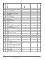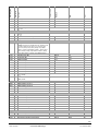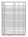
1
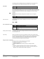
Albatros2
Zone controler
User Manual OEM
Edition 1.0
Controller series A
CE1U2353en01a
22. November 2006
RVS46..
AVS75..
AVS37..
QAA75..
QAA78..
QAA55..
Building Technologies
HVAC Products
2/26
Siemens Schweiz AG
HVAC Products
User Manual OEM
CE1U2353en01a
22. November 2006
Table of contents
1
Overview of OEM settings ............................................................................... 4
2
The settings in detail...................................................................................... 15
2.1
Operator section ............................................................................................ 15
Operation and display.................................................................................... 15
2.2
Heating circuits .............................................................................................. 15
mixing valve control ....................................................................................... 15
2.3
Domestic hot water........................................................................................ 16
Setpoints........................................................................................................ 16
Release ......................................................................................................... 16
2.4
Pump H1/H2 .................................................................................................. 17
pump H1 ........................................................................................................ 17
2.5
Primary controller / system pump .................................................................. 17
flow temperature setpoint limitations ............................................................. 17
mixing valve control ....................................................................................... 18
2.6
DHW storage tank ......................................................................................... 19
Release ......................................................................................................... 19
Charging control ............................................................................................ 19
Charging time limitation ................................................................................. 20
Discharging protection................................................................................... 20
Overtemperature protection........................................................................... 21
DHW push ..................................................................................................... 21
2.7
Configuration ................................................................................................. 21
Building and room model............................................................................... 21
Parameters .................................................................................................... 22
2.8
LPB................................................................................................................ 22
Error / maintenance / alarms ......................................................................... 22
Range of action of changeover...................................................................... 22
2.9
Error............................................................................................................... 23
History 1...10 ................................................................................................. 23
2.10
Diagnostics consumers ................................................................................. 23
Heating circuit 1, heating circuit 2, heating circuit P ..................................... 23
3/26
Siemens Schweiz AG
HVAC Products
User Manual OEM
Table of contents
CE1U2353en01a
22. November 2006
1
Overview of OEM settings
The table below shows all available settings up to the heating engineer level. However,
certain operating lines may be hidden, depending on the type of unit.
Max
Unit
O = OEM
Minimum
Function
User level
Operating line
Time of day and date
1
E Hours/minutes
2
E Day/month
3
E Year
5
F Start of summertime
6
F End of summertime
Operator section
20
E Language
F = heating engineer
Default value
E = enduser
I = commissioning
BZ = operating line
Legend
25.03
25.10
00:00
01.01
2004
01.01
01.01
23:59
31.12
2099
31.12
31.12
hh:mm
dd.mm
yyyy
dd.mm
dd.mm
German
-
Temporarily
-
Off
-
Off
-
German ¦ …
22
F
Info
Temporarily ¦ Permanently
26
F
Operation lock
Off ¦ On
27
F
Programming lock
Off ¦ On
30
O
Data:read
No
No ¦ Yes
31
O
Data:write
No
No ¦ Yes
40
I
Used as
Room unit 1
-
Heating circuit 1
-
Commonly with HC1
-
Commonly with HC1
-
Heating circuit 1
-
Room unit 1 ¦ Room unit 2 ¦ Operator unit ¦Service unit
42
I
assignment room unit 1
Heating circuit 1 ¦ Heating circuits 1 and 2
44
I
Operation HC2
Commonly with HC1 ¦ Independently
46
I
Operation HCP
Commonly with HC1 ¦ Independently
48
I
Action occupancy button
None ¦ Heating circuit 1 ¦ Heating circuit 2 ¦ Commonly
54
F
70
F
Wireless
120
I
Readjustment room sensor
Software version
0.0
-
Binding
No
-3
0
3
99.9
°C
-
No ¦ Yes
121
I
Test mode
Off
Off ¦ On
130
I
Room unit 1
-
-
-
-
-
-
-
-
Missing ¦ Ready ¦ No reception ¦ Change batt
131
I
Room unit 2
Missing ¦ Ready ¦ No reception ¦ Change batt
132
I
Outside sensor
Missing ¦ Ready ¦ No reception ¦ Change batt
133
I
Repeater
Missing ¦ Ready ¦ No reception
4/26
Siemens Schweiz AG
HVAC Products
User Manual OEM
Overview of OEM settings
CE1U2353en01a
22. November 2006
Default value
-
Unit
Function
Operator unit
Max
User level
I
Minimum
Operating line
134
-
-
-
No
-
Mo - Su
-
Missing ¦ Ready ¦ No reception ¦ Change batt
135
I
Service unit
Missing ¦ Ready ¦ No reception ¦ Change batt
138
I
Delete all devices
No ¦ Yes
Time prog heating circuit 1
500
E Preselection
Mo - Su ¦ Mo - Fr ¦ Sa - Su ¦ Mo ¦ Tu ¦ We ¦ Th ¦ Fr ¦ Sa
¦Su
501
502
503
504
505
506
516
E
E
E
E
E
E
E
1st phase on
1st phase off
2st phase on
2st phase off
3st phase on
3st phase off
Default values
6:00
22:00
24:00
24:00
24:00
24:00
No
00:00
00:00
00:00
00:00
00:00
00:00
24:00
24:00
24:00
24:00
24:00
24:00
hh:mm
hh:mm
hh:mm
hh:mm
hh:mm
hh:mm
-
No ¦ Yes
Time prog heating circuit 2
520
E Preselection
Mo - Su
-
Mo - Su ¦ Mo - Fr ¦ Sa - Su ¦ Mo ¦ Tu ¦ We ¦ Th ¦ Fr ¦ Sa
¦Su
521
522
523
524
525
526
536
E
E
E
E
E
E
E
1st phase on
1st phase off
2st phase on
2st phase off
3st phase on
3st phase off
Default values
6:00
22:00
24:00
24:00
24:00
24:00
No
00:00
00:00
00:00
00:00
00:00
00:00
24:00
24:00
24:00
24:00
24:00
24:00
hh:mm
hh:mm
hh:mm
hh:mm
hh:mm
hh:mm
-
No ¦ Yes
Time program 3 / HCP
540
E Preselection
Mo - Su
-
Mo - Su ¦ Mo - Fr ¦ Sa - Su ¦ Mo ¦ Tu ¦ We ¦ Th ¦ Fr ¦ Sa
¦Su
541
542
543
544
545
546
556
E
E
E
E
E
E
E
1st phase on
1st phase off
2st phase on
2st phase off
3st phase on
3st phase off
Default values
6:00
22:00
24:00
24:00
24:00
24:00
No
00:00
00:00
00:00
00:00
00:00
00:00
24:00
24:00
24:00
24:00
24:00
24:00
hh:mm
hh:mm
hh:mm
hh:mm
hh:mm
hh:mm
-
No ¦ Yes
Time program 4 / DHW
560
E Preselection
Mo - Su
-
Mo - Su ¦ Mo - Fr ¦ Sa - Su ¦ Mo ¦ Tu ¦ We ¦ Th ¦ Fr ¦ Sa
¦Su
561
562
563
564
565
566
E
E
E
E
E
E
1st phase on
1st phase off
2st phase on
2st phase off
3st phase on
3st phase off
6:00
22:00
24:00
24:00
24:00
24:00
00:00
00:00
00:00
00:00
00:00
00:00
24:00
24:00
24:00
24:00
24:00
24:00
hh:mm
hh:mm
hh:mm
hh:mm
hh:mm
hh:mm
5/26
Siemens Schweiz AG
HVAC Products
User Manual OEM
Overview of OEM settings
CE1U2353en01a
22. November 2006
-
Periode 1
-
Unit
No
Max
Default values
Minimum
Default value
User level
E
Function
Operating line
576
No ¦ Yes
Holidays heating circuit 1
641
E Preselection
Period 1 ¦ Period 2 ¦ Period 3¦ Period 4¦ Period 5¦ Period
6¦ Period 7¦ Period 8
642
643
648
E
E
E
Start
End
Operating level
--.-01.01
--.-01.01
Frost protection
31.12
31.12
dd.mm
dd.mm
-
Frost protection ¦ Reduced
Holidays heating circuit 2
651
E Preselection
Periode 1
-
Period 1 ¦ Period 2 ¦ Period 3¦ Period 4¦ Period 5¦ Period
6¦ Period 7¦ Period 8
652
653
658
E
E
E
Start
End
Operating level
--.-01.01
--.-01.01
Frost protection
31.12
31.12
dd.mm
dd.mm
-
Frost protection ¦ Reduced
Holidays heating circuit P
661
E Preselection
Periode 1
-
Period 1 ¦ Period 2 ¦ Period 3¦ Period 4¦ Period 5¦ Period
6¦ Period 7¦ Period 8
662
663
668
E
E
E
Start
End
Operating level
--.-01.01
--.-01.01
Frost protection
31.12
31.12
dd.mm
dd.mm
-
20.0
16
10.0
35.0
1.50
0.0
Off
BZ 712
BZ 714
4
BZ 710
0.10
-4.5
BZ 716
BZ 710
BZ 712
35
4.00
4.5
°C
°C
°C
°C
°C
-
18
−−−/8
-3
− − − / -10
8
8
80
BZ 740
20
−−−/0
−−−
− − − / 0.5
5
−−−/0
Down to reduced setpoint
30
10
BZ 741
95
100
4
20
°C
°C
°C
°C
%
°C
°C
-
0
0
−−−
-15
On
0
0
− − − / -30
-30
360
360
10
BZ 800
min
min
°C
°C
-
10
0
50
°C
Frost protection ¦ Reduced
Heating circuit 1
710
E Comfort cooling setpoint
712
E Reduced setpoint
714
E Frost protection setpoint
716
F Comfort setpoint max
720
E Heating curve slope
721
F Heating curve displacement
726
F Heating curve adaption
Off ¦ On
730
732
740
741
750
760
770
780
E
F
I
I
F
F
F
F
Summer/winter heating limit
24-hour heating limit
Flow temp setpoint min
Flow temp setpoint max
Room influence
Room temp limitation
Boost heating
Quick setback
Off ¦ Down to reduced setpoint ¦ Down to frost prot
setpoint
790
791
800
801
820
F
F
F
F
F
Optimum start control max
Optimum stop control max
Reduced setp increase start
Reduced setp increase end
Overtemp prot pump circuit
830
F
Mixing valve boost
Off ¦ On
6/26
Siemens Schweiz AG
HVAC Products
User Manual OEM
Overview of OEM settings
CE1U2353en01a
22. November 2006
Default value
3-position
Unit
Function
Actuator:type
Max
User level
F
Minimum
Operating line
832
-
2-position ¦ 3-position
833
834
835
836
850
F
F
O
O
I
Switching differential 2-pos
Actuator: running time
Mixing valve Xp
Mixing valve Tn
Floor curing function
2
120
32
120
Off
0
30
1
10
20
873
100
873
°C
s
°C
s
-
95
°C
BZ 1012
BZ 1014
4
BZ 1010
0.10
-4.5
BZ 1016
BZ 1010
BZ 1012
35
4.00
4.5
°C
°C
°C
°C
°C
-
18
−−−/8
-3
− − − / -10
8
8
80
BZ 1040
20
−−−/0
−−−
− − − / 0.5
5
−−−/0
Down to reduced setpoint
30
10
BZ 1041
95
100
4
20
°C
°C
°C
°C
%
°C
°C
-
0
0
−−−
-15
On
360
360
10
BZ 1100
min
min
°C
°C
-
10
0
3-position
50
°C
-
2
120
32
120
Off
20
873
100
873
°C
s
°C
s
-
Off ¦ Functional heating ¦ Curing heating ¦
Functional/curing heating¦ Manually
851
861
I
F
Floor curing setp manually
Excess heat draw
25
0
Always
Off ¦ Heating mode ¦ Always
872
F
With prim contr/system pump
Yes
No ¦ Yes
900
I
Optg mode changeover
Protection
Protection ¦ Recuced
Heating circuit 2
1010 E Comfort cooling setpoint
1012 E Reduced setpoint
1014 E Frost protection setpoint
1016 F Comfort setpoint max
1020 E Heating curve slope
1021 F Heating curve displacement
1026 F Heating curve adaption
20.0
16
10.0
35.0
1.50
0.0
Off
Off ¦ On
1030
1032
1040
1041
1050
1060
1070
1080
E
F
I
I
F
F
F
F
Summer/winter heating limit
24-hour heating limit
Flow temp setpoint min
Flow temp setpoint max
Room influence
Room temp limitation
Boost heating
Quick setback
Off ¦ Down to reduced setpoint ¦ Down to frost prot
setpoint
1090
1091
1100
1101
1120
F
F
F
F
F
Optimum start control max
Optimum stop control max
Reduced setp increase start
Reduced setp increase end
Overtemp prot pump circuit
1130
1132
F
F
Mixing valve boost
Actuator:type
1133
1134
1135
1136
1150
F
F
O
O
F
Switching differential 2-pos
Actuator: running time
Mixing valve Xp
Mixing valve Tn
Floor curing function
0
0
− − − / -30
-30
Off ¦ On
2-position ¦ 3-position
0
30
1
10
Off ¦ Functional heating ¦ Curing heating ¦
Functional/curing heating¦ Manually
7/26
Siemens Schweiz AG
HVAC Products
User Manual OEM
Overview of OEM settings
CE1U2353en01a
22. November 2006
Default value
25
0
Always
1172
F
With prim contr/system pump
Unit
Function
Floor curing setp manually
Excess heat draw
Max
User level
F
F
Minimum
Operating line
1151
1161
95
°C
Off ¦ Heating mode ¦ Always
Yes
No ¦ Yes
1200
I
Optg mode changeover
Protection
Protection ¦ Recuced
Heating circuit P
1300 E Operating mode
Automatic
-
Protection ¦ Automatic ¦ Reduced ¦ Comfort
1310
1312
1314
1316
1320
1321
1326
E
E
E
F
E
F
F
1330
1332
1340
1341
1350
1360
1370
1380
E
F
F
F
F
F
F
F
Comfort cooling setpoint
Reduced setpoint
Frost protection setpoint
Comfort setpoint max
Heating curve slope
Heating curve displacement
Heating curve adaption
20.0
16
10.0
35.0
1.50
0.0
Off
BZ 1012
BZ 1014
4
BZ 1010
0.10
-4.5
BZ 1016
BZ 1010
BZ 1012
35
4.00
4.5
°C
°C
°C
°C
°C
-
18
−−−/8
-3
− − − / -10
8
8
80
BZ 1040
20
−−−/0
−−−
− − − / 0.5
5
−−−/0
Down to reduced setpoint
30
10
BZ 1041
95
100
4
20
°C
°C
°C
°C
%
°C
°C
-
0
0
−−−
-15
On
360
360
10
BZ 1100
min
min
°C
°C
-
Off ¦ On
Summer/winter heating limit
24-hour heating limit
Flow temp setpoint min
Flow temp setpoint max
Room influence
Room temp limitation
Boost heating
Quick setback
Off ¦ Down to reduced setpoint ¦ Down to frost prot
setpoint
1390
1391
1400
1401
1420
F
F
F
F
F
Optimum start control max
Optimum stop control max
Reduced setp increase start
Reduced setp increase end
Overtemp prot pump circuit
0
0
− − − / -30
-30
Off ¦ On
1450
I
Floor curing function
Off
-
Off ¦ Functional heating ¦ Curing heating ¦
Functional/curing heating¦ Manually
1451
1455
1456
1461
I
F
F
F
Floor curing setp manually
Floor curing setp current
Floor curing day current
Excess heat draw
25
0
0
0
0
0
Always
95
95
32
°C
°C
°C
BZ 1614 OEM
BZ 1610
80
°C
°C
°C
-
Off ¦ Heating mode ¦ Always
1172
F
With prim contr/system pump
Yes
No ¦ Yes
1500
I
Optg mode changeover
Protection
Protection ¦ Recuced
Domestic hot water
1610 E Nominal setpoint
1612 F Reduced setpoint
1614 O Nominal setpoint max
1620 I
Release
55
BZ 1612
40
8
65
8
Time programs HCs
24h/day ¦ Time programs HCs ¦ Time program 4/DHW
8/26
Siemens Schweiz AG
HVAC Products
User Manual OEM
Overview of OEM settings
CE1U2353en01a
22. November 2006
Default value
MC shifting, PC absolute
Unit
Function
Charging priority
Max
User level
I
Minimum
Operating line
1630
-
Fixed weekday
-
Absolute ¦ Shifting ¦ None ¦ MC shifting, PC absolute
1640
F
Legionella function
Off ¦ Periodically ¦ Fixed weekday
1641
1642
F
F
Legionella funct periodically
Legionella funct weekday
3
1
Montag
7
Days
−−−
65
30
On
23:50
95
360
hh:mm
°C
min
-
Monday ¦ Tuesday ¦ Wednesday ¦ Thursday ¦ Friday ¦
Saturday ¦ Sunday
1644
1645
1646
1647
F
F
F
F
1660
F
Legionella funct time
Legionella funct setpoint
Legionella funct duration
Legionella funct circ pump
− − − / 00:00
55
− − − / 10
Off ¦ On
Release of the circulating pump
DHW release
-
On
-
Time program 3/HCP ¦ DHW release ¦ Time program
4/DHW
1661
F
Circulating pump cycling
Off ¦ On
1663 F Circulaton setpoint
Pump H1/H2
2008 O H1 DHW charging priority
45
8
80
°C
Yes
No ¦ Yes
2010
F
H1 Excess heat draw
On
Off ¦ On
2014
F
H1 prim contr/system pump
Yes
-
No ¦ Yes
2033
O
H2 DHW charging priority
Yes
No ¦ Yes
2035
F
H2 Excess heat draw
On
Off ¦ On
2039
F
H2 prim contr/system pump
Yes
-
No ¦ Yes
Primary controller / system pump
2110 O Flow temp setpoint min
2111 O Flow temp setpoint max
2130 O Mixing valve boost
2132 O Actuator:type
8
8
80
8
10
0
3-position
95
95
50
°C
°C
°C
2-position ¦ 3-position
2133
2134
2135
2136
Solar
3810
3811
3812
3830
3831
3840
3850
3860
O
O
O
O
Switching differential 2-pos
Actuator: running time
Mixing valve Xp
Mixing valve Tn
2
120
32
120
0
30
1
10
20
873
100
873
°C
°C
°C
°C
F
F
F
F
F
F
F
F
Temp diff on
Temp diff off
Charg temp min DHW st tank
Collector start function
Min run time collector pump
Collector frost protection
Collector overtemp prot
Evaporation heat carrier
8
4
−−−
−−−
60
−−−
−−−
−−−
BZ 3811
0
−−−/8
−−−/5
5
− − − / -20
− − − / 30
− − − / 60
40
BZ 3812
95
60
120
5
200
200
°C
°C
°C
min
s
°C
°C
°C
9/26
Siemens Schweiz AG
HVAC Products
User Manual OEM
Overview of OEM settings
CE1U2353en01a
22. November 2006
Max
Unit
Minimum
Default value
Function
User level
Operating line
DHW storage tank
5010 O Charging
16
0
With B3/B31
30
°C
5
0
150
− − − / 10
Automatic
20
600
°C
min
80
90
60
Off
BZ 5051 OEM
95
95
°C
°C
°C
-
Several times / day
Once/day ¦ Several times/day
5020
5022
F
F
Increase of the flow temperature setpoint
Type of charging
5024
5030
5040
O
O
O
Switching diff
Charging time limitation
Discharging protection
5050
5051
5055
5056
F
O
F
F
Charging temp max
Storage tank temp max
Recooling temp
Recooling heat gen/HCs
5057
F
Recooling collector
With B3 ¦ With B3/B31 ¦ With B3, legio B3/B31
Off ¦ Always ¦ Automatically
8
8
8
Off ¦ On
Off
-
Substitute
-
DHW release
-
DHW sensor
-
Off ¦ Summer ¦ Always
5060
F
Electric immersion heater:operating mode
Substitute ¦ Summer ¦ Always
5061
F
Electric immersion heater:release
24h/day ¦ DHW release¦ Time program4/ DHW
5062
F
El immersion heater control
External thermostat ¦ DHW sensor
5070
O
Automatic push
On
Off ¦ On
5085
F
Excess heat draw
On
-
Off ¦ On
5092
F
With prim contr/system pump
No
No ¦ Yes
5093
F
With solar integration
Yes
No ¦ Yes
Configuration
5710 I
Heating circuit 1
On
-
On
-
Sensors
-
charging pump
-
None
-
None
-
None
-
Off ¦ On
5715
I
Heating circuit 2
Off ¦ On
5730
I
DHW sensor B3
Sensor ¦ Thermostat
5731
I
DHW controlling element Q3
None ¦ Charging pump ¦ Diverting valve
5890
I
Relay output QX1
None ¦ Circulating pump Q4 ¦ El imm heater DHW K6 ¦
Collector pump Q5 ¦ H1 pump Q15 ¦ Alarm output K10 ¦
2nd pump speed HC1 Q21 ¦ 2nd pump speed HC2 Q22
¦ 2nd pump speed HCP Q23 ¦ Heat circuit pump HCP
Q20 ¦ H2 pump ¦ Q18 primary pump Q14
5930
I
Sensor input BX1
None ¦ DHW sensor B31 ¦ Collector sensor B6 ¦ DHW
circulation sensor B39
5931
I
Sensor input BX2
None ¦ DHW sensor B31 ¦ Collector sensor B6 ¦ DHW
circulation sensor B39
10/26
Siemens Schweiz AG
HVAC Products
User Manual OEM
Overview of OEM settings
CE1U2353en01a
22. November 2006
Function input H1
Optg mode change HCs+DHW ¦ Optg mode changeover
HCs ¦ Optg mode changeover HC1 ¦ Optg mode
changeover HC2 ¦ Optg mode changeover HCP ¦
Error/alarm message ¦ Min flow temp setpoint ¦ Excess
heat discharge
5951
I
Contact type H1
Unit
Max
Minimum
Default value
User level
I
Function
Operating line
5950
Optg mode change
HCs+DHW
-
NO contact
-
NC ¦ NO
5952
5954
5956
5960
I
I
I
I
Min flow temp setpoint H1
Heat request 10V H1
Pressure value 3.5V H1
Function input H2
Optg mode change HCs+DHW ¦ Optg mode changeover
HCs ¦ Optg mode changeover HC1 ¦ Optg mode
changeover HC2 ¦ Optg mode changeover HCP ¦ Heat
generation lock ¦ Error/alarm message ¦ Min flow temp
setpoint ¦ Heat request ¦ Pressure measurement
5961
I
Contact type H2
70
8
100
5
5.0
0.0
Optg mode change
HCs+DHW
120
130
10.0
NO contact
°C
°C
bar
-
-
NC ¦ NO
5962
6014
I
I
Min flow temp setpoint H2
Function mixing group 1
70
8
Heating circuit
120
°C
-
Heating circuit ¦ Prim contr/system pump
6020
I
Function extension module 1
No function
-
No function
-
None ¦ Multi-functional ¦ Heating circuit ¦ Solar DHW ¦
Prim contr/system pump
6021
I
Function extension module 2
None ¦ Multi-functional ¦ Heating circuit ¦ Solar DHW ¦
Prim contr/system pump
6097
F
Sensor type collector
NTC
NTC 10k ¦ Platinum 1000
6030
I
Relay output QX21
None
-
None
-
None
-
None
-
None ¦ Circulating pump Q4 ¦ El imm heater DHW K6 ¦
Collector pump Q5 ¦ H1 pump Q15 ¦ Alarm output K10 ¦
2nd pump speed HC1 Q21 ¦ 2nd pump speed HC2 Q22
¦ 2nd pump speed HCP Q23 ¦ Heat circuit pump HCP
Q20 ¦ H2 pump ¦ Q18 primary pump Q14
6031
I
Relay output QX22
None ¦ Circulating pump Q4 ¦ El imm heater DHW K6 ¦
Collector pump Q5 ¦ H1 pump Q15 ¦ Alarm output K10 ¦
2nd pump speed HC1 Q21 ¦ 2nd pump speed HC2 Q22
¦ 2nd pump speed HCP Q23 ¦ Heat circuit pump HCP
Q20 ¦ H2 pump ¦ Q18 primary pump Q14
6040
I
Sensor input Bx21
None ¦ DHW sensor B31 ¦ Collector sensor B6 ¦ DHW
circulation sensor B39
6041
I
Sensor input BX22
None ¦ DHW sensor B31 ¦ Collector sensor B6 ¦ DHW
circulation sensor B39
Sensor type collector
6097
NTC
NTC 10k ¦ Platinum 1000
6098
6100
6110
6112
6120
F
F
F
O
F
Readjustm collector sensor
Readjustm outside sensor
Time constant building
Gradient room model
Frost protection plant
0
0.0
15
60
On
-20
-3.0
0
0
20
3.0
50
300
°C
°C
h
min/°C
-
Off ¦ On
6200
I
Saving sensors
No
-
No ¦ Yes
11/26
Siemens Schweiz AG
HVAC Products
User Manual OEM
Overview of OEM settings
CE1U2353en01a
22. November 2006
Default value
No
Unit
Function
Save parameters
Max
User level
O
Minimum
Operating line
6204
No ¦ Yes
6205
F
Reset to default parameters
No
-
No ¦ Yes
6212
6215
6217
6220
6222
LPB
6600
6601
6604
I
I
I
F
O
Check no heat source 1
Check no storage tank
Check no heating circuits
Software version
Device hours run
0
0
0
0
0
0
I
F
F
Device address
Segment address
Bus power supply function
1
0
0
0
Automatic
199999
199999
199999
99.9
500 000
h
16
14
-
Off ¦ Automatically
6605
F
Bus power supply state
On
-
Off ¦ On
6610
O
Display system messages
Yes
No ¦ Yes
6612
O
Alarm delay
No
No ¦ Yes
6620
O
Action changeover functions
System
-
Local
-
All heating circuits in the
system
Autonomous
-
Segment ¦ System
6621
F
Summer changeover
Locally¦ Centrally
6625
F
DHW assignment
Local HCs ¦ All HCs in segment ¦ All HCs in system
6640
I
Clock mode
-
Autonomously ¦ Slave without remote ¦ Slave with
remote setting ¦ Master
6650
Error
6710
F
Outside temp source
0
I
Reset:alarm relay
No
0
239
-
No ¦ Yes
6740
6741
6800
6802
6804
6806
6808
6810
6812
6814
F
F
F
F
F
F
F
F
F
F
F
F
F
F
F
F
F
F
Flow temp 1 alarm
Flow temp 2 alarm
History 1
Error code 1
History 2
Error code 1
History 3
Error code 1
History 4
Error code 1
History 5
Error code 1
History 6
Error code 6
History 7
Error code 7
History 8
Error code 8
−−−
−−−
-
− − − / 10
− − − / 10
240
240
min
min
0
255
-
0
255
-
0
255
-
0
255
-
0
255
-
0
255
-
0
255
-
0
255
-
12/26
Siemens Schweiz AG
HVAC Products
User Manual OEM
Overview of OEM settings
CE1U2353en01a
22. November 2006
No
Unit
History 9
Error code 9
History 10
Error code 10
Reset history
Max
F
F
F
F
O
Minimum
Default value
6820
Function
6818
User level
Operating line
6816
0
255
-
0
255
-
No ¦ Yes
Maintenance/service
7140 E manual control
Off
-
Off ¦ On
7150 I
Simulation outside temp
7170 I
Telephone customer service
Input/output test
7700 I
Relay test
-
-50.0
50
No test
°C
-
No test ¦ Everything off ¦ DHW pump Q3 ¦ Heating circuit
pump Q2 ¦ Heat circ mix valve op Y1 ¦ Heat circ mix
valve cl Y2 ¦ Relay output QX1 ¦ Relay output QX21
module 1 ¦ Relay output QX22 module 1 ¦ Relay output
QX23 module 1¦ Relay output QX21 module 2 ¦ Relay
output QX22 module 2 ¦ Relay output QX23module 2
7730
7732
7750
7820
7821
7830
7831
7832
7833
7841
I
I
I
I
I
I
I
I
I
I
Outside temp B9
Flow temp B1
DHW temp B3
Sensor temp BX1
Sensor temp BX2
Sensor temp BX21 module 1
Sensor temp BX22 module 1
Sensor temp BX21 module 2
Sensor temp BX22 module 2
Contact state H1
0
0
0
0
Open
-50.0
0.0
0.0
-28.0
-28.0
-28
-28
-28
-28
50
140
140
350
350
350
350
350
350
°C
°C
°C
°C
°C
°C
°C
°C
°C
-
Open ¦ Closed
7846
I
Contact state H2
Open
-
-
-
Open ¦ Closed
Status:
8000 I
State heating circuit 1
8001 I
State heating circuit 2
8002 I
State heating circuit P
8003 I
State DHW
8007 I
State solar
Diagnostics heat source
8510 I
Collector temp 1
8511 I
Collector temp 1 max
8512 I
Collector temp 1 min
8513 I
dT collector 1/DHW
8514 I
dT collector 1/buffer
8530 F Hours run solar yield
8531 F Hours run collect overtemp
Diagnostics consumers
8700 I
Outside temperature
8703 I
Outside temp attenuated
8704 I
Composite outside temperature
0
0
-
-28.0
-28.0
-28.0
-28.0
-28.0
0
0
350
350
350
350
350
65535
65535
°C
°C
°C
°C
°C
h
h
-
-50.0
-50.0
-50.0
50.0
50.0
50.0
°C
°C
°C
13/26
Siemens Schweiz AG
HVAC Products
User Manual OEM
Overview of OEM settings
CE1U2353en01a
22. November 2006
Default value
-
Unit
Function
Heating circuit pump Q2
Max
User level
I
Minimum
Operating line
8730
-
-
-
-
-
Off ¦ On
8731
I
Heat circ mix valve op Y1
Off ¦ On
8732
I
Heat circ mix valve cl Y2
Off ¦ On
8740
8741
8742
8743
8744
8760
I
I
O
I
I
I
8761
I
Room temp 1
Room setpoint 1
Room temp 1 model
Flow temp 1
Flow temp setpoint 1
Heating circuit pump Q6
-
0.0
4.0
0.0
0.0
0.0
50.0
35.0
50.0
140.0
140.0
°C
°C
°C
°C
°C
-
Off ¦ On
Heat circ mix valve op Y5
-
-
-
-
Off ¦ On
8762
I
Heat circ mix valve cl Y6
Off ¦ On
8770
8771
8772
8773
8774
8800
8801
8802
8803
8820
I
I
O
I
I
I
I
O
I
I
8830
8831
8832
8835
8930
8931
8950
8951
9000
9001
9031
I
I
I
I
I
I
I
I
I
I
I
9050
I
Room temp 2
Room setpoint 2
Room temp 2 model
Flow temp 2
Flow temp setpoint 2
Room temp P
Room setpoint P
Room temp P model
Flow temp setpoint P
DHW pump Q3
-
0.0
4.0
0.0
0.0
0.0
0.0
4.0
0.0
0.0
50.0
35.0
50.0
140.0
140.0
50.0
35.0
50.0
140.0
°C
°C
°C
°C
°C
°C
°C
°C
°C
-
-
0.0
8.0
0.0
0.0
0.0
0.0
0.0
0.0
5.0
5.0
140.0
80.0
140.0
140.0
140.0
140.0
140.0
140.0
130.0
130.0
°C
°C
°C
°C
°C
°C
°C
°C
°C
°C
-
Off ¦ On
DHW temp 1
DHW temp setpoint
DHW temp 2
DHW circulation temp
Primary controller temp
Primary controller setpoint
Common flow temp
Common flow temperature setpoint
Flow temp setpoint H1
Flow temp setpoint H2
Relay output QX1
Off ¦ On
Relay output QX21 module 1
-
-
-
-
-
-
-
-
-
-
-
-
Off ¦ On
9051
I
Relay output QX22 module 1
Off ¦ On
9052
I
Relay output QX23 module 1
Off ¦ On
9053
I
Relay output QX21 module 2
Off ¦ On
9054
I
Relay output QX22 module 2
Off ¦ On
9055
I
Relay output QX23 module 2
Off ¦ On
14/26
Siemens Schweiz AG
HVAC Products
User Manual OEM
Overview of OEM settings
CE1U2353en01a
22. November 2006
2
The settings in detail
2.1 Operator section
Operation and display
Line no.
Operating line
30
Data:read
No
Yes
31
Data:write
No
Yes
Data:read
The setting data of all operating levels are copied from the controller to the memory of
the operator unit. This means that previous data in the operator unit will be overwritten.
Data:write
With the exception of the data listed below, the setting data of all operating levels are
transferred from the memory of the operator unit to the connected controller. Previous
setting data in the controller will be overwritten.
The following data will not be overwritten:
Line no.
3
130
131
132
133
134
135
138
516
536
556
576
6222
6600
6601
6650
Operating line
Year
Room unit 1
Room unit 2
Outside sensor
Repeater
Operator unit
Service unit
Delete all devices
default values
default values
default values
default values
Device hours run
device address
Segment address
Outside temp source
2.2 Heating circuits
mixing valve control
HC1
835
836
Line no.
HC2 HC3P
1135
1136
Operating line
Mixing valve Xp
Mixing valve Tn
Mixing valve Xp
The proportional band defines within which change of the control variable ∆x (∆T of the
flow) the whole correcting span y (valve travel) is traversed.
The smaller the proportional band, the greater the change of the manipulated variable
∆y at a given change of the controlled variable ∆x.
Mixing valve Tn
The integral action time is the period of time the controller’s I-part would require to
produce the same change of the manipulated variable as the P-part
15/26
Siemens Schweiz AG
HVAC Products
User Manual OEM
The settings in detail
CE1U2353en01a
22. November 2006
An adjustment of the integral action time changes the valve’s rate of response.
The longer the integral action time Tn, the slower the response of the controlled
system.
2392Z08
y
1
Xp
t
Tn
x
t
@
2.3 Domestic hot water
Setpoints
Line no.
Operating line
1614
Nominal setpoint max
This operating line is used to limit the “Nominal setpoint“ (operating line 1610) at the
top.
Release
Line no.
Operating line
1620
Release
24h/day
Time programs HCs
Time program 4 / DHW
24h/day
The DHW temperature is constantly maintained at the nominal DHW setpoint,
independent of any time programs.
2371Z18
Example:
0
6
12
18
24
h
Time programs HCs
The DHW setpoint is switched between the nominal DHW setpoint and the reduced
DHW setpoint according to the heating circuits’ time programs. The first switch-on point
of each period is shifted forward in time by one hour.
16/26
Siemens Schweiz AG
HVAC Products
User Manual OEM
The settings in detail
CE1U2353en01a
22. November 2006
2377Z16
Example:
0
5 6
12
16 17
h
24
Time program 4 / DHW
For DHW heating, time switch program 4 of the local controller is used. The set
switching times of that program are used to switch between the nominal DHW setpoint
and the reduced DHW setpoint. This way, the DHW is heated independently of the
heating circuits.
2373Z24
Example:
0
6
12
18
24
h
2.4 Pump H1/H2
pump H1
Line no.
H1
H2
2008 2033
Operating line
H1/H2 DHW charging priority
Off ¦ On
H1/H2 DHW charging
priority
When using this setting, the connected pump H1/H2 can be excluded from / included in
the effect of DHW charging priority.
In the case of a ventilation system, for example, it is thus possible to ensure a constant
supply of heat with no impact from DHW charging priority.
2.5 Primary controller / system pump
flow temperature setpoint limitations
Line no.
Operating line
2110
2111
Flow temp setpoint min
Flow temp setpoint max
Using this limitation, a temperature range for the flow temperature setpoint can be
defined. If the requested flow temperature setpoint reaches the relevant limit and the
heat request increases or decreases, the flow temperature setpoint will be maintained
at the maximum or minimum limit.
17/26
Siemens Schweiz AG
HVAC Products
User Manual OEM
The settings in detail
CE1U2353en01a
22. November 2006
TVmax
max
TVw
2358Z09
TV
akt
TVmin
min
0
10
TVw
TVmax
Tvmin
20
30
40
50
60
70
80
90
100 °C
Current flow temperature setpoint
Flow temperature setpoint maximum
Flow temp setpoint min
mixing valve control
Line no.
Operating line
2130
2132
2133
2134
2135
2136
Mixing valve boost
Actuatortype
Switching differential 2-pos
Actuator running time
Mixing valve Xp
Mixing valve Tn
Mixing valve boost
For mixing, the actual value of the boiler flow temperature must be higher than the
required setpoint of the mixing valve flow temperature since otherwise that temperature
cannot be controlled. The controller generates the boiler temperature setpoint based on
the increase set here and the current flow temperature setpoint.
Actuator:type
Selection of the type of actuator determines the way the control action impacts the type
of mixing valve actuator used.
Switching differential 2pos
For the 2-position actuator, the 2-position switching differential must also be adapted.
This is not required when using 3-position actuators.
Actuator: running time
Setting the actuator running time for the mixing valve used.
Mixing valve Xp
The proportional band defines within which change of the control variable ∆x (∆T of the
flow) the whole correcting span y (valve travel) is traversed.
The smaller the proportional band, the greater the change of the manipulated variable
∆y at a given change of the controlled variable ∆x.
Mixing valve Tn
The integral action time is the period of time the controller’s I-part would require to
produce the same change of the manipulated variable as the P-part
An adjustment of the integral action time changes the valve’s rate of response.
The longer the integral action time Tn, the slower the response of the controlled
system.
2392Z08
y
1
Xp
t
Tn
x
t
18/26
Siemens Schweiz AG
HVAC Products
User Manual OEM
The settings in detail
CE1U2353en01a
22. November 2006
@
2.6 DHW storage tank
Release
Line no.
Operating line
5010
Charging
Once / day
Several times / day
Charging
Selection of charging “Once/day“ or “Several times/day” is active only if DHW release is
set according to the time programs of the heating circuits.
Once / day
Release of DHW charging is given 2.5 hours before the first heat request fom the
heating circuit is received. Then, the reduced DHW setpoint applies for the whole day.
Heizprogramm
Time
program
Einmal
Once
perpro
day Tag
DHW
release
TWW-Freigabe
2.5h
In the case of continuous heating (with no setback periods), release of DHW charging
is given at 0:00. The same rule also applies if the first request for heat from the heating
circuit is received before 02:30. If a request for heat is delivered at midnight, DHW
charging is released after the first setback period, but no earlier than 2.5 hours before
midnight.
Day
Tag11
Day
Tag2 2
Day 33
Tag
Day
Tag4 4
Time
program
Heizprogramm
DHW
release
TWW-Freigabe
2.5h
0:00
24:00
2.5h
2.5h
22:00
2.5h
Several times / day
When selecting “Several times/day“, release of DHW charging is put forward in time by
1 hour against the periods of time the heating circuit calls for heat, and is then
maintained during these periods of time.
Heizprogramm
Time
program
Several times
perTag
Mehrmals
pro
day
DHW
release
TWW-Freigabe
1h
1h
Charging control
Switching diff
Line no.
Operating line
5024
Switching diff
If the DHW temperature is lower than the current setpoint minus the switching
differential set here, DHW charging will be started.
DHW charging will be terminated when the temperature reaches the current setpoint.
19/26
Siemens Schweiz AG
HVAC Products
User Manual OEM
The settings in detail
CE1U2353en01a
22. November 2006
When DHW heating is released for the first time in a 24-hour period, forced charging
will be initiated. DHW charging is also started when the DHW temperature lies within
the switching differential, provided it does not lie less than 1 K below the setpoint.
Charging time limitation
Charging time limitation
Line no.
Operating line
5030
Charging time limitation
During DHW charging, space heating may obtain no or too little energy, depending on
the selected charging priority (operating line 1630) and the type of hydraulic circuit. For
this reason, it is often practical to set a time limit to DHW charging.
--Charging time limitation is deactivated. The DHW is heated up to the nominal setpoint,
even if space heating temporarily obtains too little heat.
10 – 600
DHW charging is stopped after the set period of time in minutes and then locked for the
same time before it is resumed. During this period of time, the heat produced by the
boiler is made available for space heating. This cycle is repeated until the nominal
DHW setpoint is reached.
When space heating is switched off (summer operation, Eco function, etc.), DHW
charging will not be stopped, independent of the selected setting.
Discharging protection
Discharging protection
Line no.
Operating line
5040
Discharging protection
This function ensures that the DHW charging pump (Q3) will be activated only when the
boiler temperature is sufficiently high.
•
With sensor
The charging pump will be activated only when the boiler temperature reaches the
level of the DHW temperature plus half the charging boost. If, during charging, the
boiler temperature drops to a level below the DHW temperature plus 1/8 the
charging boost, the charging pump will be deactivated again. If 2 DHW sensors are
parameterized for DHW charging, the lower temperature is used for the discharging
protection function (usually sensor B31).
•
With thermostat
The charging pump will be activated only when the boiler temperature lies above
the nominal DHW setpoint. If, during charging, the boiler temperature drops below
the nominal DHW temperature minus the DHW switching differential, the charging
pump will be deactivated again.
Off
Function is deactivated.
Always
The function is always active.
Automatic
The function is active only if the heat source is unable to deliver heat, or is not available
(fault, heat generation lock).
20/26
Siemens Schweiz AG
HVAC Products
User Manual OEM
The settings in detail
CE1U2353en01a
22. November 2006
Overtemperature protection
Storage tank temp max
Line no.
Operating line
5051
Storage tank temp max
If the storage tank reaches the maximum storage tank temperature set here, the
collector pump will be deactivated. It will be released again when the storage tank
temperature drops 1 °C below the maximum storage tank temperature.
The protective collector overtemperature function can reactivate the collector pump
until the storage tank’ s safety temperature is reached.
T
TSpMax
TSp
L
2354Z10
1°C
1
0
t
TSpMax
TSp
L
Storage tank temp max (operating line 5051)
Actual value of the storage tank temperature
Storage tank charging: 1 = on, 0 = off
DHW push
Line no.
Operating line
5070
Automatic push
Off
On
Automatic push
The DHW push can be triggered either manually or automatically.
With the DHW push, the DHW is heated up once until the nominal setpoint is reached.
Off
The DHW push must be triggered manually.
On
If the DHW temperature falls below the reduced setpoint (operating line 1612) by at
least 2 switching differentials (operating line 5024), one-time charging to the nominal
DHW setpoint (operating line 1610) will take place again.
The automatic DHW push only works when the DHW operating mode is activated.
2.7 Configuration
Building and room model
Gradient room model
Line no.
Operating line
6112
Gradient room model
The room model gradient gives the period of time in minutes room heating needs to
raise the temperature by 1 °C. The setting made applies to all circuits.
21/26
Siemens Schweiz AG
HVAC Products
User Manual OEM
The settings in detail
CE1U2353en01a
22. November 2006
The setting is used to calculate the fictive room temperature of rooms that have no
room temperature sensor installed (operating lines 8742, 8772, and 8802).
Parameters
Line no.
Operating line
6204
Save parameters
.
The current parameter settings can be saved as new standard settings. Exempted from
this are the following operating pages: Time of day and date, operator section, wireless,
and all time programs, as well as the number of operating hours and the different
counters.
Important:
With this process, the factory settings will be overwritten and can no longer be
retrieved!
Device hours run
Line no.
Operating line
6222
Device hours run
This indicates the total number of operating hours since the controller was first
commissioned.
2.8 LPB
Error / maintenance / alarms
Line no.
Operating line
6610
6612
6620
Display system messages
Alarm delay
Action changeover functions
Segment
System
Display system messages
This setting enables system messages transmitted via LPB to be suppressed at the
connected operator unit.
Alarm delay
Delivery of the alarm to the OCI can be delayed in the basic unit by setting a delay.
This ensures that unnecessary notifications of a service center resulting from short-time
errors (e.g. temperature limiter cut out, communication error) can be prevented.
It is to be noted, however, that errors occurring for a short period of time, and
reoccurring constantly and rapidly, will also be filtered.
Range of action of changeover
The range of action of central changeover can be defined.
This applies to the following types of limitation:
• Optg mode changeover
• Summer changeover (when selecting ”Central“ on setting line 6621)
Entries:
• Segment: Changeover takes place with all controllers in the same segment.
• System: Changeover takes place with all controllers in the entire system (in all
segments). The controller must be located in segment 0!
22/26
Siemens Schweiz AG
HVAC Products
User Manual OEM
The settings in detail
CE1U2353en01a
22. November 2006
2.9 Error
History 1...10
Line no.
Operating line
6820
Reset history
No
Yes
Reset history
The error history with the last 10 errors will be deleted.
2.10 Diagnostics consumers
Heating circuit 1,
heating circuit 2,
heating circuit P
Room temperature 1 / 2 /
P model
Line no.
Operating line
8742
8772
8802
Room temp 1 model
Room temp 2 model
Room temp P model
The room model calculates a fictive room temperature for rooms that have no room
temperature sensor. The value calculated for each heating circuit is indicated on these
operating lines.
This allows boost heating, quick setback and optimum start and stop control to be
implemented with no need for using a room temperature sensor.
The calculation takes into account the attenuated outside temperature (operating line
8703), the room model gradient (operating line 6112) for switching to a higher setpoint,
and the building’s time constant (operating line 6110) for switching to a lower setpoint.
23/26
Siemens Schweiz AG
HVAC Products
User Manual OEM
The settings in detail
CE1U2353en01a
22. November 2006
Index
A
action changeover functions......................................22
attenuated outside temperature ................................23
Automatic push..........................................................21
B
building’s time constant .............................................23
C
charging DHW ...........................................................19
Charging time limitation.............................................20
copy settings .............................................................15
D
Data:read...................................................................15
Data:write ..................................................................15
Device hours run .......................................................22
DHW charging ...........................................................19
DHW push .................................................................21
DHW switching differential ........................................19
E
error reset..................................................................23
F
flow temp setpoint max..............................................17
flow temp setpoint min...............................................17
G
Gradient room model...........................................21, 23
H
history reset...............................................................23
hours run device........................................................22
I
integral action time ..............................................16, 18
L
limitation of charging time......................................... 20
M
maximum nominal setpoint....................................... 16
model room temperature 1 / 2 / P............................. 23
N
Nominal setpoint max ............................................... 16
O
once / day ................................................................. 19
Optimum start control ............................................... 23
optimum stop control ................................................ 23
P
proportional band................................................ 15, 18
push.......................................................................... 21
Q
quick setback / boost heating ................................... 23
R
reset
error history ......................................................... 23
room model gradient................................................. 21
room temperature model 1 / 2 / P............................. 23
S
Save parameters ...................................................... 22
Saving parameter settings........................................ 22
several times / day.................................................... 19
Summer changeover ................................................ 22
switching differential DHW........................................ 19
24/26
Siemens Schweiz AG
HVAC Products
Benutzerhandbuch
2 The settings in detail
CE1U2354de01a
22. November 2006
3
Proof of change
All changes since the last issue (see front side) are registered in the original document
(Winwordfile) with the Winwordfunktion " Highlight ".
To make these passages visible, go forward with the following key combination:
Show: Ctrl+Shift+?’
Hide: Ctrl+Shift+`
Or put the same functionality about the following Winword menu:
Menu: [Tools] - [Optionen]
Option: [Highlight]
In the Printfile (PDF) the change proof is not evident.’
25/26
Siemens Schweiz AG
HVAC Products
User Manual OEM
CE1U2353en01a
22. November 2006
Siemens Schweiz AG
Siemens Switzerland Ltd
Building Technologies Group / HVAC Products
Gubelstrasse 22
CH -6301 Zug
Tel. +41 41-724 24 24
Fax +41 41-724 35 22
www.sbt.siemens.com
© 2005-2006 Siemens Building Technologies AG
Subject to alteration
26/26
Siemens Schweiz AG
HVAC Products
User Manual OEM
3 Proof of change
CE1U2353en01a
22. November 2006