1
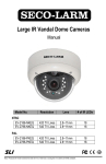
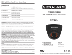
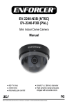
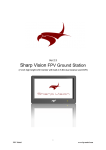
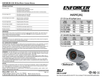
ENFORCER Ball-Mount Indoor/Outdoor IR Camera Manual
ENFORCER Ball-Mount Indoor/Outdoor IR Camera Manual
R
E
C
R
O
O
E
F
D
I
V
EN
®
TROUBLE SHOOTING
The screen is blank
• Check that the camera is powered up.
• Check that the monitor is powered up.
• Check that the video cable connecting the camera to the monitor is connected properly.
The screen image is dim
• Clean the lens (using a soft, clean cloth).
• Check that the light source is adequate.
The screen image has poor
contrast
• Adjust the monitor’s contrast knob.
• Change the position of the camera.
The screen image flickers
• Change the position of the camera.
The screen image is distorted
• Check “Focus” adjustment.
• Change the position of the camera.
The camera case is hot
• Check that the correct power supply is in use.
MANUAL
EV-122C-DVAVQ
IMPORTANT Users and installers of this product are responsible for ensuring this product complies with all
national, state, and local laws and statutes related to monitoring and recording audio and video signals.
SECO-LARM will not be held responsible for the use of this product in violation of any current laws or statutes.
WARNING Stop using the camera if you see a malfunction like smoke or unusual heat, as it could cause fire or
electric shock. Do not open the case of this device, as there are no field-serviceable components inside.
FCC COMPLIANCE STATEMENT Information to the user: This equipment has been tested and found to comply with the
limits for a Class A digital device, pursuant to Part 15 of the FCC rules. These limits are designed to provide reasonable protection
against harmful interference when the equipment is operated in a commercial environment. This equipment generates, uses and
can radiate radio frequency energy and, if not installed and used in accordance with the instruction manual, may cause harmful
interference to radio communications. Operation of this equipment in a residential area is likely to cause harmful interference in
which case the user will be required to correct the interference at his own expense.
Color Ball-Mount Vandal-Resistent,
Indoor/Outdoor IR Dome Camera
with Varifocal Lens, 36 LEDs,
and Split Glass Technology
WARRANTY This SECO-LARM product is warranted against defects in material and workmanship while used in
normal service for a period of one (1) year from the date of sale to the original consumer customer. SECO-LARM’s
obligation is limited to the repair or replacement of any defective part if the unit is returned, transportation prepaid, to
SECO-LARM.
This Warranty is void if damage is caused by or attributed to acts of God, physical or electrical misuse or abuse, neglect,
repair, or alteration, improper or abnormal usage, or faulty installation, or if for any other reason SECO-LARM determines
that such equipment is not operating properly as a result of causes other than defects in material and workmanship.
The sole obligation of SECO-LARM, and the purchaser’s exclusive remedy, shall be limited to replacement or repair only,
at SECO-LARM’s option. In no event shall SECO-LARM be liable for any special, collateral, incidental, or consequential
personal or property damages of any kind to the purchaser or anyone else.
NOTICE
The information and specifications printed in this manual are current at the time of publication. However, the SECO-LARM
policy is one of continual development and improvement. For this reason, SECO-LARM reserves the right to change
specifications without notice. SECO-LARM is also not responsible for misprints or typographical errors.
Copyright © 2008 SECO-LARM U.S.A., Inc. All rights reserved. This material may not be reproduced or copied, in whole
or in part, without the written permission of SECO-LARM.
SECO-LARM® U.S.A., Inc.
16842 Millikan Avenue, Irvine, CA 92606
Website: www.seco-larm.com
Tel: 800-662-0800 / 949-261-2999 Fax: 949-261-7326 E-mail: [email protected]
®
PICSN4
SECO-LARM®
iMUIRVandalBallMntLargeCam.pmd
Note: Products with model number that ends with “Q” or have a round green “Q” sticker represents RoHS compliant
ENFORCER Ball-Mount Indoor/Outdoor IR Camera Manual
ENFORCER Ball-Mount Indoor/Outdoor IR Camera Manual
Parts List
Specifications
___________________________________________________EV-122C-DVAVQ
____________________________________________________________________________________________________________
Type
___________________________________________________Ball-Mount
______________________Color
___________Dome
_____________Camera
______________________________________________________________
1 x Camera Ball
1 x Case
1 x Base
4 x Screws with wall anchors
1 x Small screwdriver
1 x Hex wrench
1 x Manual
1 x DC plug to terminal jack
Chip
___________________________________________________1/3”
_______CCD,
__________Sony
___________________________________________________________________________________________
420
TV
lines
Resolution
_______________________________________________________________________________________________________________________________________________________________
Pickup
_____________elements
______________________________________510
_______x___492
_______pixels
___________________________________________________________________________________________
2:1
interlace,
V:
Scanning
system
_________________________________________________________________________
____59.94Hz,
_______________H:
_____15.734KHz
______________________________________________________________
Sync
___________________________________________________Internal
____________________________________________________________________________________________________________
p-p
Video
___________output
________________________________________1V
______
______composite
_________________output,
____________75
_____ohms
______________________________________________________________
Lens
___________________________________________________Varifocal
_______________4mm~9mm,
____________________F1.6
_________________________________________________________________________
(850nm)
IR
_____LEDs
______________________________________________36
_____x___LEDs
__________
__________________________________________________________________________________________
to
100’
IR
_____distance
______________________________________________Up
______
____
_______(30m)
___________________________________________________________________________________________
o
o
38
~90
beam
spread
IR
view
angle
____________________________________________________________________________________
_________________________________________________________________
__________
Case
Camera
Ball
4x
Screws
Base
Power
Connector
(0
IR
Minimum
illumination
__________________
_________________________________0.3
______lux
______
____lux
_____with
________
____on)
___________________________________________________________________________
Gamma
_______________correction
____________________________________0.45
____________________________________________________________________________________________________________
S/N
ratio
________
___________________________________________>48dB
____________________________________________________________________________________________________________
Electronic
1/60~1/100,000
sec.
Shutter
______________control
_____________________________________Auto
_________
________________Shutter
_____________(AES),
____________
__________________________
________________________________
BNC
Connector
Automatic
___________________gain
________control
________________________Auto
____________________________________________________________________________________________________________
Auto
White
balance
_______________________________________________________________________________________________________________________________________________________________
±10%
Power
____________source
_______________________________________12VDC
_____________
_______________________________________________________________________________________________
150mA
(IR
Power
consumption
_______500mA
____________(IR
______on)
_________________________________________________________________
_____________________________________________________________________off),
Operating
__________________temperature
_________________________________4°~122°
______________F___(-20°~50°
________________C)
___________________________________________________________________________
weatherproof
Enclosure
___________________________________________________IP66
_________
___________________________________________________________________________________________________
21
”__x___3__15__/_16
x__100mm)
Dimensions
___________________________________________________4____/_32
___
__”____(118
________
__________________________________________________________________________
1.7
lb.
(752g)
Weight
_______________________________________________________________________________________________________________________________________________________________
Cable
___________length
________________________________________34”
______(86cm)
______________________________________________________________________________________________________
Dimensions:
(Use included small screwdriver to adjust zoom and focus.)
Zoom
Focus
315/16”
(100mm)
421/32” (118mm)
Before Starting:
1. Please read this manual carefully and keep it for future
reference.
2. Use the camera within given temperature and electrical limits.
3. While the camera is weatherproof to IP66 standard, do not
mount the camera where it is exposed to rain or other moisture,
or in humid or dusty places.
4. Do not point the camera at the sun. Heat could damage the
camera, even when not in use.
5. Do not mount the camera in areas exposed to radiation, strong
Installation:
1. Run a 12VDC power supply wire and a video cable with a male
BNC connector through the wall to where the camera is to be
mounted.
2. Loosen the set screws with the included hex wrench and remove
the case from the base.
NOTE - The camera ball is NOT attached to the case or the
base. It sits loose inside the case. Therefore, be very careful
when removing the case from the base to not drop the camera
ball.
3. Mount the base to the wall using the four included mounting
screws. If the wall is made of dry wall, brick, or similar material,
it may be necessary to use the included plastic screw anchors.
4. Run the camera's BNC and power connectors through the
camera base, and connect to the video and power wires that
magnetic fields, or strong electrical signals.*
6. Do not open or disassemble the camera. There are no userserviceable parts inside.
7. Do not drop the camera or subject it to strong vibrations.
* Note: Many video monitors produce strong electromagnetic
fields close to the display CRT, especially when the monitor
is turned on or during de-Gaussing, which occurs
automatically with many monitors when the monitor is turned
on.
were run through the wall.
5. Put the case over the camera ball onto the base, being careful to
not drop the camera ball.
6. Holding the case loosely on the base, turn the camera ball to the
desired direction.
7. Once the camera ball is in the desired direction, tighten the set
screws with the included hex wrench. However, do not tighten
them too tightly. Tighten just enough so that the case does not
move, and the camera ball does not rotate.
8. Use the included small screwdriver to adjust the zoom and the
focus of the camera ball if needed, via the holes marked
"ZOOM" and "FOCUS" on the top of the camera ball.
9. Do a final test of the video camera and the monitor.