1
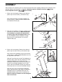
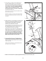
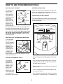
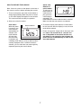
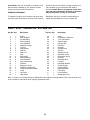
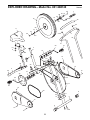
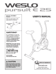
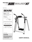
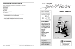
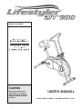
¨
Model No. 831.288140
CAUTION
Read all precautions and
instructions in this manual
before using this equipment.
Keep this manual for future
reference.
USERÕS MANUAL
SEARS, ROEBUCK AND CO., HOFFMAN ESTATES, IL 60179
TABLE OF CONTENTS
IMPORTANT PRECAUTIONS . . . . . . . . . . . . . . . . . . . . . . . . . . . . . . . . . . . . . . . . . . . . . . . . . . . . . . . . . . . . .2
BEFORE YOU BEGIN . . . . . . . . . . . . . . . . . . . . . . . . . . . . . . . . . . . . . . . . . . . . . . . . . . . . . . . . . . . . . . . . . . .3
ASSEMBLY . . . . . . . . . . . . . . . . . . . . . . . . . . . . . . . . . . . . . . . . . . . . . . . . . . . . . . . . . . . . . . . . . . . . . . . . . . .4
HOW TO USE THE EXERCISE CYCLE . . . . . . . . . . . . . . . . . . . . . . . . . . . . . . . . . . . . . . . . . . . . . . . . . . . . . .6
MAINTENANCE AND TROUBLE-SHOOTING . . . . . . . . . . . . . . . . . . . . . . . . . . . . . . . . . . . . . . . . . . . . . . . . .8
CONDITIONING GUIDELINES . . . . . . . . . . . . . . . . . . . . . . . . . . . . . . . . . . . . . . . . . . . . . . . . . . . . . . . . . . . . .9
PART LIST . . . . . . . . . . . . . . . . . . . . . . . . . . . . . . . . . . . . . . . . . . . . . . . . . . . . . . . . . . . . . . . . . . . . . . . . . . .10
EXPLODED DRAWING . . . . . . . . . . . . . . . . . . . . . . . . . . . . . . . . . . . . . . . . . . . . . . . . . . . . . . . . . . . . . . . . .11
HOW TO ORDER REPLACEMENT PARTS . . . . . . . . . . . . . . . . . . . . . . . . . . . . . . . . . . . . . . . . . . .Back Cover
FULL 90 DAY WARRANTY . . . . . . . . . . . . . . . . . . . . . . . . . . . . . . . . . . . . . . . . . . . . . . . . . . . . . . .Back Cover
IMPORTANT PRECAUTIONS
WARNING: To reduce the risk of serious injury, read the following important precautions before
using the exercise cycle.
1. Read all instructions in this manual before
using the exercise cycle. Use the exercise
cycle only as described.
9. Keep hands away from the flywheel and
other moving parts.
10. Always keep your back straight when using
the exercise cycle. Do not arch your back.
2. It is the responsibility of the owner to ensure
that all users of the exercise cycle are adequately informed of all precautions.
11. If you feel pain or dizziness while exercising,
stop immediately and begin cooling down.
3. Use the exercise cycle indoors, away from
moisture and dust. Place the exercise cycle
on a level surface, with a mat beneath it to
protect the floor or carpet from damage.
12. The exercise cycle is intended for home use
only. Do not use the exercise cycle in a commercial, rental or institutional setting.
4. Inspect and tighten all parts regularly.
Replace any worn parts immediately.
13. The decal shown below has been placed on
the exercise cycle. If the decal is missing, or
if it is not legible, please call our toll-free
HELPLINE to order a free replacement decal.
Apply the decal in the location shown.
5. Make sure the seat pin is inserted through
the seat post. Do not insert the seat pin
under the seat post.
6. Keep children under the age of 12 and pets
away from the exercise cycle at all times.
7. The exercise cycle should not be used by
persons weighing more than 250 pounds.
8. Wear appropriate clothing when exercising;
do not wear loose clothing that could become
caught on the exercise cycle. Always wear
athletic shoes for foot protection.
WARNING: Before beginning this or any exercise program, consult your physician. This is especially important for persons over the age of 35 or persons with pre-existing health problems. Read all
instructions before using. SEARS assumes no responsibility for personal injury or property damage
sustained by or through the use of this product.
2
BEFORE YOU BEGIN
Thank you for selecting the new LIFESTYLER¨ DT
900. The LIFESTYLER¨ DT 900 provides you with a
low-impact workout in the convenience and privacy of
your own home.
toll-free HELPLINE at 1-800-736-6879, Monday
through Saturday, 7 a.m. until 7 p.m. Central Time
(excluding holidays). To help us assist you, please
mention the product model number when calling. The
model number is 831.288140.
For your benefit, read this manual carefully before
you use the LIFESTYLER¨ DT 900. If you have
questions after reading the manual, please call our
Before reading further, please familiarize yourself with
the parts that are labeled in the drawing below.
Handlebars
Seat
Seat Pin
Seat Post
Console
Resistance Knob
Flywheel
Pedal
Side Shield
BACK
FRONT
RIGHT SIDE
3
ASSEMBLY
Place all parts of the exercise cycle in a cleared area and remove the packing materials. Do not dispose of the
packing materials until assembly is completed. Assembly requires a phillips screwdriver
and an adjustable wrench
(not included).
1. Refer to the inset drawing. Remove the indicated
plastic cap from the Frame (1). Discard the cap.
1
Cap
1
32
Next, slide the bracket on the Rear Stabilizer (2)
into the Frame (1). Attach the Rear Stabilizer with
four Stabilizer Screws (32).
1
2
2. Align the Front Stabilizer (5) with the saddle bracket
on the front of the Frame (1). Make sure that the
Front Stabilizer is turned so the square holes
are facing away from the saddle bracket. Attach
the Front Stabilizer with two Stabilizer Carriage
Bolts (18), two Curved Washers (14), and two
Stabilizer Nuts (30).
2
14
30
1
5
Square Holes
3. Refer to the inset drawing. Remove the indicated
plastic caps from the Frame (1). Discard the caps.
3
Next, slide the Left Handlebar (40) into the left side
of the Frame (1). Slide the Right Handlebar (41) into
the right side of the Frame.
Slide the Foam Grip (42) onto the Top Handlebar (3).
Push the ends of the Foam Grip towards the center
of the Top Handlebar so the ends of the Top
Handlebar are uncovered. Insert the Top Handlebar
into the Left and Right Handlebars (40, 41) and
attach it with two Handlebar Screws (33). Slide the
Foam Grip back so it covers the Handlebar Screws.
Align the holes in the Left and Right Handlebars
(40, 41) with the holes in the Frame (1). Attach the
Handlebars with four Handlebar Bolts (36), four
Handlebar Washers (38), and four Locknuts (37).
Make sure that the Locknuts are in the hexagonal
holes in the Frame.
4
42
18
Caps
33
1
33
3
40
41
36
38
37
38
1
4. The Console (7) requires two "AA" batteries (not
included). Alkaline batteries are recommended.
Refer to the inset drawing. Remove the battery door
from the back of the Console. Press two batteries
into the battery compartment. Make sure that the
negative ends of the batteries (marked ÒÐÓ) are
touching the springs in the battery compartment.
Re-attach the battery door.
4
7
Console
Wire
Console
Plate
Next, plug the console wire into the socket on the
back of the Console (7).
Slide the Console (7) onto the console plate. Note:
The Console attaches by friction; it does not snap
into place.
Batteries
Battery Door
5. Attach the Seat (11) to the Seat Post (10) with three
Seat Nuts (9) and three Seat Washers (8). Note:
The Seat Nuts and Seat Washers may be preattached to the underside of the Seat.
5
11
Insert the Seat Post (10) into the Frame (1). Press
the Frame Bushing (4) into the Frame. Note: The
Frame Bushing may be pre-assembled.
8
8
9
Next, align one of the holes in the Seat Post (10)
with the hole in the Frame (1). Insert the Seat Pin
(31) through the Frame and the Seat Post to select
the desired seat height. Make sure to insert the
Seat Pin through one of the holes in the Seat
Post; do not insert the Seat Pin under the Seat
Post. Tighten the Seat Pin into the Frame.
9
10
4
31
6. Identify the Right Pedal (22). (The Right Pedal is
marked with an ÒR.Ó) Using an adjustable wrench,
tighten the Right Pedal clockwise into the right arm
of the Crank (20).
1
6
20
Tighten the Left Pedal (21) counterclockwise into
the left arm on the Crank (20).
22
R
R
21
L
7. Make sure that all parts are properly tightened before you use the exercise cycle.
5
HOW TO USE THE EXERCISE CYCLE
HOW TO ADJUST THE SEAT
BATTERY INSTALLATION
For effective exercise, the seat
must be at the
Seat
proper height. As
you pedal, there
should be a slight
bend in your
Seat
knees when the
Post
Frame
pedals are in the
Seat
lowest position. To
Pin
adjust the seat,
first hold the seat
and turn the seat
pin counterclockwise to remove it. Next, align one of
the holes in the seat post with the hole in the frame.
Insert the seat pin through the frame and the seat
post to select the desired height. Make sure to insert
the seat pin through the seat post; do not insert
the seat pin under the seat post. Tighten the seat
pin into the frame.
Before the console can be operated, two Ò"AA"Ó batteries must be installed. If you have not installed batteries, see assembly step 4 on page 5.
DESCRIPTION OF THE CONSOLE
The console features five modes that provide instant
exercise feedback during your workouts. The modes
are described below.
SPEED
DISTANCE
TIME
SCAN
CALORIES
HOW TO ADJUST THE PEDALING RESISTANCE
To vary the intensity of your exercise, the pedaling
Resistance
resistance can be
Knob
adjusted. The
resistance is controlled with the
resistance knob.
To increase the
resistance, turn
the resistance
knob clockwise; to decrease the resistance, turn the
knob counterclockwise.
Button
¥ SpeedÑDisplays your pedaling speed, in miles per
hour.
LEVELING THE EXERCISE CYCLE
Your exercise
cycle features
adjustable endcaps on the front
stabilizer. If the
exercise cycle
tends to rock
when in use,
adjust one or both
of the endcaps by
turning them until
the exercise cycle is stable.
Display
Mode
Indicators
¥ TimeÑDisplays the elapsed time. Note: If you stop
pedaling for ten seconds or longer, the time mode
will pause until you resume.
Endcap
¥ DistanceÑDisplays the total distance you have pedaled, in miles.
Stabilizer
¥ CalorieÑDisplays the approximate number of calories you have burned.
¥ ScanÑDisplays the speed, time, distance, and calorie modes, for 5 seconds each, in a repeating cycle.
6
Speed, time,
distance or
calorie modeÑ
To select one of
these modes for
continuous display, press the
console button
repeatedly. The
mode indicators will show which mode is selected.
Make sure that the scan mode is not selected.
HOW TO OPERATE THE CONSOLE
Note: If there is a piece of clear plastic on the face of
the console, remove it before operating the console.
1. To turn on the power, press the console button or
simply begin pedaling. When the power is turned
on, the entire display will appear for two seconds.
The console will then be ready for operation.
2. Select one of the five modes:
3. To reset the display, hold down the console button
for two seconds. After the display is reset, the scan
mode will be selected.
Scan modeÑ
Mode Indicators
When the power
is turned on, the
scan mode will
automatically be
selected. One
mode indicator
will show that
the scan mode
is selected, and
a flashing mode indicator will show which mode is
currently displayed. Note: If a different mode is
selected, you can select the scan mode again by
repeatedly pressing the console button.
4. To turn off the power, simply wait for about four minutes. Note: The console has an Òauto-offÓ feature. If the pedals are not moved and the console button is not pressed for four minutes, the
power will turn off automatically in order to conserve the batteries.
7
MAINTENANCE AND TROUBLE-SHOOTING
Inspect and tighten all parts of the exercise cycle regularly. Replace any worn parts immediately.
HOW TO ADJUST THE RESISTANCE STRAP
If there is not enough pedaling resistance when the
resistance knob is turned to the highest setting, the
resistance strap may need to be adjusted. To adjust
the resistance
strap, first turn
the resistance
Slotted
knob to the
Tab
lowest setting.
Next, locate
Resistance
the slotted tab
Strap
on the front of
the exercise
cycle. Grip the
main part the
resistance
strap underneath the slotted tab and pull it towards
the slot. When a little slack is created, pull the end of
the resistance strap tight and then let go of the strap.
Turn the crank for a moment to make sure that there
is not too much resistance.
The exercise cycle can be cleaned with a soft, damp
cloth. Avoid spilling liquid on the console. Keep the
console out of direct sunlight or the display may be
damaged. Remove the batteries when storing the
exercise cycle.
BATTERY REPLACEMENT
If the console does not function properly, the batteries
should be replaced. See assembly step 4 on page 5.
In addition, make sure that the console wire is
plugged into the console.
HOW TO TIGHTEN THE CRANK
If the arms of
the crank
become
loose, they
should be
Slotted
tightened in
Crank
Crank
order to preNut
Nut
vent excessive wear.
Loosen the
Crank Arm
crank nut on
the left arm of
the crank.
Place the end of a standard screwdriver in one of the
slots in the slotted crank nut. Lightly tap the screwdriver with a hammer to turn the slotted crank nut
counterclockwise until the arms are no longer loose.
Do not overtighten the slotted crank nut. When the
slotted crank nut is properly tightened, retighten the
crank nut.
HOW TO ADJUST THE CHAIN
The exercise cycle features a chain that must be kept
properly adjusted. If the chain causes excessive noise
or slips as you pedal, the chain should be adjusted.
To tighten the
chain, loosen,
but do not
remove, the
axle nuts on
both sides of
the flywheel.
Pull the flyAxle
wheel slightly
Nut
forwards.
Make sure that
the flywheel is
straight and tighten the axle nuts.
8
CONDITIONING GUIDELINES
The following guidelines will help you to plan your
exercise program. Remember that proper nutrition
and adequate rest are essential for successful results.
If your goal is to burn fat, adjust the intensity of your
exercise until your heart rate is near the lowest number in your training zone as you exercise.
For maximum fat burning, adjust the intensity of your
exercise until your heart rate is near the middle number in your training zone as you exercise.
WARNING: Before beginning this or any exercise program, consult your physician. This is
especially important for persons over the age
of 35 or persons with pre-existing health
problems.
Aerobic Exercise
If your goal is to strengthen your cardiovascular system, your exercise must be Òaerobic.Ó Aerobic exercise is activity that requires large amounts of oxygen
for prolonged periods of time. This increases the
demand on the heart to pump blood to the muscles,
and on the lungs to oxygenate the blood. For aerobic
exercise, adjust the intensity of your exercise until
your heart rate is near the highest number in your
training zone.
EXERCISE INTENSITY
Whether your goal is to burn fat or to strengthen your
cardiovascular system, the key to achieving the
desired results is to exercise with the proper intensity.
The proper intensity level can be found by using your
heart rate as a guide. The chart below shows recommended heart rates for fat burning, maximum fat
burning, and cardiovascular (aerobic) exercise.
HOW TO MEASURE YOUR HEART RATE
To measure your
heart rate, first
exercise for at
least four minutes.
Then, stop exercising and place two
fingers on your
wrist as shown.
Take a six-second
heartbeat count,
and multiply the
result by 10 to find your heart rate. For example, if
your six-second heartbeat count is 14, your heart rate
is 140 beats per minute. (A six-second count is used
because your heart rate will drop rapidly when you
stop exercising.)
To find the proper heart rate for you, first find your age
on the bottom of the chart (ages are rounded off to
the nearest ten years). Next, find the three numbers
above your age. The three numbers are your Òtraining
zone.Ó The lowest number is the recommended heart
rate for fat burning; the middle number is the heart
rate for maximum fat burning; the highest number is
the heart rate for aerobic exercise.
WORKOUT GUIDELINES
Each workout should include the following three
important parts:
A warm-up, consisting of 5 to 10 minutes of stretching and light exercise. A proper warm-up increases
your body temperature, heart rate, and circulation in
preparation for exercise.
Burning Fat
To burn fat effectively, you must exercise at a relatively low intensity level for a sustained period of time.
During the first few minutes of exercise, your body
uses easily accessible carbohydrate calories for energy. Only after the first few minutes of exercise does
your body begin to use stored fat calories for energy.
Training zone exercise, consisting of 20 to 30 minutes of exercising with your heart rate in your training
zone. (During the first few weeks of your exercise program, do not keep your heart rate in your training
zone for longer than 20 minutes.)
9
A cool-down, with 5 to 10 minutes of stretching. This
will increase the flexibility of your muscles and will
help to prevent post-exercise problems.
EXERCISE FREQUENCY
workouts. After a few months of regular exercise, you
may complete up to five workouts each week, if
desired. Caution: Be sure to progress at your own
pace and avoid overdoing it. Incorrect or excessive
training may result in injury to your health.
To maintain or improve your condition, plan three workouts each week, with at least one day of rest between
Remember, the key to success is make exercise a
regular and enjoyable part of your everyday life.
PART LISTÑModel No. 831.288140
Key No. Qty.
1
2
3
4
5
6
7
8
9
10
11
12
13
14
15
16
17
18
19
20
21
22
1
1
1
1
1
2
1
3
3
1
1
2
2
2
6
1
1
2
1
1
1
1
Description
R0399A
Key No. Qty.
23
24
25
26
27
28
29
30
31
32
33
34
35
36
37
38
39
40
41
42
#
#
Frame
Rear Stabilizer
Top Handlebar
Frame Bushing
Front Stabilizer
Stabilizer Endcap
Console
Seat Washer
Seat Nut
Seat Post
Seat
Side Shield
Bronze Bushing
Curved Washer
Side Shield Screw
Flywheel
Resistance Strap
Stabilizer Carriage Bolt
Crank Hardware Assembly
Crank
Left Pedal
Right Pedal
1
1
3
1
4
1
2
2
1
4
2
1
1
4
4
4
2
1
1
1
1
1
Description
Chain
Resistance Cable/Knob
7/16Ó Flat Washer
Flywheel Axle
3/8Ó Axle Nut
Odometer
Axle Nut
Stabilizer Nut
Seat Pin
Stabilizer Screw
Handlebar Screw
Resistance Spring
Sprocket
Handlebar Bolt
Locknuts
Handlebar Washer
Round Endcap
Left Handlebar
Right Handlebar
Foam Grip
UserÕs Manual
Multipurpose Tool
Note: Ò#Ó refers to a non-illustrated part. Specifications are subject to change without notice. See the back cover
of this manual for information about ordering replacement parts.
10
EXPLODED DRAWINGÑModel No. 831.288140
R0399A
7
29
27
28 25Ê
25
13
16
42
27
33
26
11
13
27
3
33
29
25
40
41
21
20
8
4
8
9
19
9
10
15
24
36
31
38
39
32
37
12
2
15
39
19
35
34
20
15
17
22
15
23
6
30
14
1
5
12
6
15
18
15
11
All replacement parts are available for immediate purchase or
special order when you visit your nearest SEARS Service Center.
To request service or to order parts by telephone, call the toll-free
numbers listed at the left.
Model No. 831.288140
QUESTIONS?
When requesting help or service, or ordering parts, please be
prepared to provide the following information:
If you find that:
¥ you need help assembling or
operating the LIFESTYLER¨ DT
900
¥ a part is missing
¥ or you need to schedule repair
service
¥ The MODEL NUMBER of the product (831.288140).
¥ The NAME of the product (LIFESTYLER¨ DT 900).
¥ The KEY NUMBER and DESCRIPTION of the PART (see the
PART LIST and the EXPLODED DRAWING on pages 10 and 11).
call our toll-free HELPLINE
1-800-736-6879
MondayÐSaturday, 7 amÐ7 pm
Central Time (excluding holidays)
REPLACEMENT
PARTS
If parts become worn and need to
be replaced, call the following tollfree number
1-800-FON-PART
(1-800-366-7278)
FULL 90 DAY WARRANTY
For 90 days from the date of purchase, if failure occurs due to defect in material or workmanship in this
SEARS BIKE EXERCISER, contact the nearest SEARS Service Center throughout the United States
and SEARS will repair or replace the BIKE EXERCISER, free of charge.
This warranty does not apply when the BIKE EXERCISER is used commercially or for rental purposes.
This warranty gives you specific legal rights, and you may also have other rights which vary from state
to state.
SEARS, ROEBUCK AND CO., DEPT. 817WA, HOFFMAN ESTATES, IL 60179
Part No. 152378 H04402AC R0399A
Printed in Taiwan © 1999 Sears, Roebuck and Co.