1
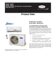
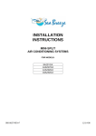
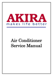
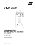
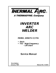
INSTALLATION
INSTRUCTIONS
MINI-SPLIT
HEAT PUMP
FOR MODELS:
12H43ZGX
18H43ZGX
950-0032-REV-E
12-14-06
TABLE OF CONTENTS
MODEL NUMBERS……………………………………………………………………………2
UNIT PARTS & FEATURES……………………………………………………………………3
INSTALLATION DIMENSION DIAGRAM……………………………………………………4
SAFETY WARNINGS……………………………………………………………………………5
SELECTION OF INSTALLATION LOCATIONS………………………………………………6
INDOOR UNIT INSTALLATION………………………………………………………………8
OUTDOOR UNIT INSTALLATION……………………………………………………………11
TESTING………………………………………………………………………………………13
PRINCIPLE……………………………………………………………………………………15
SPECIFICATIONS………………………………………………………………………………17
WARRANTY……………………………………………………………………………………18
TECHNICAL SUPPORT
IF YOU NEED TECHNICAL SUPPORT PLEASE CALL
1-(704)504-8590
SEA BREEZE Installation Kit is recommended.
Catalog number can be located on page 17.
1
MODEL NUMBERS
Heat Pump
SYSTEM MODEL
Indoor Unit
12H43ZIGX
12H43ZGX
Outdoor Unit 12H43ZOGX
12,000 BTU 208-230 VAC
13 SEER
SYSTEM MODEL
Indoor Unit
18H43ZIGX
18H43ZGX
Outdoor Unit 18H43ZOGX
18,000 BTU 208-230 VAC
13 SEER
2
UNIT PARTS & FEATURES
3
INSTALLATION DIMENSION DIAGRAM
4
SAFETY WARNINGS
z
Use Copper Wires only for Power Supply.
z
Risk of electric shock can cause injury or death. Disconnect all electric power
supplies before servicing or installation
z
Do not use excessive torque on flare nuts during connection of the
refrigeration tubes, or service valve on discharge line may be damaged.
z
Do not install indoor unit in damp or wet locations.
z
Electrical installation must be done by a qualified technician according to the
instruction manual and in accordance with local electrical standards.
z
Certified Power supply conductors must be used.
5
SELECT INSTALLATION LOCATION
CAUTION : The air conditioning unit must be installed by professional
technicians.
BASIC REQUIREMENTS FOR INSTALLATION POSITION
Installation of Either unit in the following locations may cause malfunction.
Locations exposed to:
Machine oil
Flammable or corrosive gasses
High frequency waves (i.e. from radio equipment, medical equipment, etc.)
INDOOR UNIT LOCATION
Intake and outlet should not be obstructed.
The wall the unit is to be mounted on should allow for a clear hole for the condensation drain and
the refrigeration lines.
The wall the unit is mounted on should be strong enough to bear the weight and vibration of the
unit.
Allow for proper clearances around the unit - see installation dimension diagram.
Location should allow easy access for maintenance and removal of air filter.
Position unit and remote control at least 3 feet from electric appliances such as televisions, radios,
etc.
Keep unit and remote out of direct sunlight and/or florescent lighting and away from any excessive
heat source, steam, or flammable materials.
OUTDOOR UNIT LOCATION
Allow sufficient ventilation around the unit - see installation dimension diagram.
The air intake and outlet should not be obstructed.
Position unit so that noise and outlet airflow will not inconvenience neighbors.
Position unit on a solid foundation. Location should be able to withstand the full weight and
vibration of the unit.
Installation should not be performed in the following locations exposed to: machine oil, flammable
or corrosive gases, high - frequency waves (i.e. from radio equipment, medical equipment, etc.)
Installation location should beyond the reach of children.
6
SELECT INSTALLATION LOCATION (Cont)
ELECTRICAL SAFETY REQUIREMENTS
The power supply must be of rated voltage via special circuit for air-conditioner. The power supply wire gauge
is specified in page 9.
Applicable voltage range: the normal operation range of voltage is 90%~110% of rated voltage.
Do not pull the power cable with excessive force.
System grounding to be completed by a licensed technician, using National Electrical Code procedures and
UL materials. In the fixed line there must be an electrical leakage protection switch and an air switch with
sufficient capacity. The air switch shall also have the magnetic tripping and thermal tripping functions to
achieve protection of both short-circuit and overload.
The minimum clearance between air conditioner and flammable surface is 5 ft.
GROUNDING REQUIREMENT
As air-conditioning unit is of Class I electrical appliance, reliable grounding measures must be taken
for it.
The green cable inside the air conditioner is for grounding and shall not be used for other purposes nor can it
be cut. Do not tighten with tapping screw; otherwise electric shock will be caused.
The ground resistance shall be in conformity with the requirements of state standard.
The user power supply shall have reliable grounding terminal. It is prohibited to connect the grounding wire to
the following items:
Water Supply Pipe
Gas Pipe
Sewage Pipe
Other positions that are considered to be unreliable by professionals.
7
INDOOR UNIT INSTALLATION
INSTALL THE REAR PANEL-MOUNTING PLATE
Always mount rear panel horizontally.
Hold the rear panel on the wall where you want the unit to be located and ensure that it is level
using a plumb line or level. Once leveled, mark the screw locations on the wall.
Fasten the rear panel to the wall at the location marked using the screws supplied with the unit.
Insure that the panel has been mounted firmly to withstand the weight of the unit for about 132 lbs,
with the weight being evenly distributed by each screw.
INSTALL THE PIPING HOLE
Select the location for the piping hole - either left-positioned or
right-positioned (see installation dimension diagram).
Make piping hole in the wall approximately 2.5 inches in diameter at a
slight downward slant (this ensures proper drainage).
Insert a piping-hole sleeve in the hole (i.e. PVC pipe) to prevent the
connection piping and wiring from being damaged
indoor
wall
pipe
outdoor
sealing gum
2. 5"
protective
pipe
INSTALL DRAINAGE HOSE EXTENSION (OPTIONAL)
Drainage hose extension is included with unit, for use if attached drainage line is not long enough
for your application.
twist
ridge
Please note that the extension can be installed after
existing drainage pipe is fed through wall later in the
installation process, if it is determined later that it is
necessary.
Do not wrench or bend drainage hose or extension.
WIRE THE INDOOR UNIT
CAUTION: All electrical wiring must be done by a qualified technician in accordance with
local electrical codes.
A separate circuit breaker must be provided.
AC power for the indoor unit is provided by the power cable that runs between the outdoor unit and
the indoor unit.
If a disconnect switch is required for the indoor unit, it must be properly rated. Disconnect switch
may be installed by breaking the individual wires connected to pins (N1) and (3) of the control
cable. See table 1 for recommended value.
8
INDOOR UNIT INSTALLATION (Cont)
MODEL
INTERCONNECTING
WIRE GAUGE
12H43ZGX
18H43ZGX
16 AWG
16 AWG
-Table 1-
POWER
SUPPLY WIRE
GAUGE
14 AWG
14 AWG
CIRCUIT
BREAKER
15 AMP
20 AMP
Terminal board diagram
covering
plate
MODEL
12H43ZGX
18H43ZGX
terminal board
power
cable
connection groove
cable
NOTE:
Power connection cable is provided in the installation kit (sold separately). If the cable is not of
sufficient length, it will be necessary to purchase cable for this purpose.
Do not splice cable.
9
INDOOR UNIT INSTALLATION (Cont)
PREPARE REFRIGERATION LINES
Refrigeration lines and wiring can be routed from the indoor unit several different ways using the
cut-out access pieces on the back of the unit.
Bend the refrigeration lines carefully to the position needed to align with the drilled piping hole.
HANG INDOOR UNIT
Bundle the refrigeration lines, drainage hose, and wiring conduit attached to
the indoor unit and wrap them securely for enough length to extend through
the piping hole to the exterior of the building.
Note: leave remainder unwrapped to allow for remaining step in installation
of the outdoor unit and connecting the indoor unit to the outdoor unit.
Carefully push bundled lines through the piping hole.
Hang the unit on the wall by hooking the mounting slots of the unit over the
upper tabs of the rear panel.
Check to make sure the: unit is properly secured - it should feel firmly
attached to the wall, and you should not be able to slide it to the right or left.
10
OUTDOOR UNIT INSTALLATION
CONNECT REFRIGERATION LINES
Align the center of the piping flare with the relevant valve.
Use standard A/C practices to attach the connection pipes to the
proper pipes of the bundled lines coming through the wall from the
indoor unit.
Tighten the flare nut of the connection pipes using a spanner and
torque wrench. (see diagram)
Note:
Do not over-tighten flare nuts, or the connection may be damaged.
Unit is charged with enough R410A Refrigerants for a standard
designed length. For longer line set lengths additional charge must be
WEIGHED in per Table 2.
Model
12H43ZGX
18H43ZGX
Designed Length ft
19
26
fitting pipes of
indoor unit
spanner
conical?
nut
torque
wrench
Refrigerants Charge oz/ft
.21
.26
-Table 2-
INSULATE/BUNDLE REFRIGERATION LINES AND WIRING
Individually insulate all refrigeration lines and condensation drainage hose to ensure that they do
not sweat. This will help to maintain the unit at its proper capacities.
Once all lines have been properly insulated, bundle the refrigeration lines with the wiring conduit
and wrap securely to complete the run to the outdoor unit.
Note:
The condensation drainage hose should be left free of the bundled lines in order to drain properly.
INSTALL OUTDOOR CONDENSATION DRAINAGE HOSE
When the heat pump unit is heating or defrosting, wastewater forms in the
outdoor unit. This can be drained off using the outdoor drain elbow and
hose provided.
Insert the drain elbow into the hole on the base plate as shown.
Join the drain hose to the elbow and turn so that the water drains to the
desired location.
WIRE THE OUTDOOR UNIT
CAUTION:
Wrong wiring connection will cause electrical malfunction.
Do not pull the wire when it is fixed with wire clamp.
11
·
OUTDOOR UNIT INSTALLATION (Cont)
CAUTION: DO NOT CROSS WIRE
12
TESTING
NOTE:
Installation MUST be complete prior to testing.
System MUST be tested prior to operation.
LEAKAGE TEST
Use standard A/C practices to properly check refrigeration tubes and connections for any leaks
prior to system start up.
AIR PURGING AND PRESSURE TEST
Remove bonnet (cover) of gas valve on outdoor unit.
Charge system with Nitrogen to 100 PSI and check for leaks.
Evacuate Nitrogen.
Connect the gas valves of a vacuum gauge, vacuum pump, and
outdoor unit(see diagram). Start the vacuum pump and allow to run
for at least 30 minutes at a level of 500 microns or less.
Shut off the vacuum and continue to monitor vacuum gauge for
another 15 minutes. The pressure should not rise above 800 microns.
lf a vacuum of 500 microns cannot be obtained, or if it rises above
800 microns during the l5-minute monitoring period, pressurize the
system with nitrogen and look for leaks. Repair any leaks that are
found and repeat the vacuum testing.
Close the valves to the vacuum pump and gauge and disconnect
from the outdoor unit.
Tighten bonnet (cover) of gas valve and open gas and liquid valves
completely.
SYSTEM TESTING
Before testing the system, ensure that cut-off valves of the
connection pipes are opened and that all debris (such as packing
scraps, debris, etc.) are clear from the unit.
Switch on power to the system and press the ''ON/OFF'' button on the
remote control to activate the indoor unit.
Press ''MODE'' button repeatedly, taking a moment on each setting to
ensure that system functions in all modes.
If the remote control is lost, emergency run operation can be initiated
by pressing the button in the upper right corner of the indoor unit
under the cover panel. (see diagram)
13
TESTING (Cont)
INSTALLATION VERIFICATION
Have both units been securely and firmly installed?
Are all piping connections secure?
Have the refrigeration lines been sufficiently insulated?
Have you verified the length of the connection pipes and the refrigerant capacity?
Have you conducted all leakage and system tests?
Does the unit drain properly?
Are all electrical connections in compliance with local standards?
Has the unit been properly grounded?
Is the power cord as specified?
Are all air inlets and outlets free from obstruction?
14
PRINCIPLE
COOLING MODE
Principle:
The air conditioner absorbs heat from indoor air and transmits it outdoors for discharge, hence to decrease
the indoor ambient temperature. The cooling capacity decreases with the rise of outdoor ambient
temperature.
Anti-freeze Function:
If the air conditioner is running under low-temperature cooling mode, frost will appear on the surface of indoor
heat exchanger. When the temperature of indoor heat exchanger is decreased to 32℉ or below, the
microcomputer of indoor unit will stop the compressor to protect the complete unit.
HEATING MODE
Principle:
The air conditioner absorbs heat from outdoor air and transmits it indoors for emission, hence to increase the
air temperature in the room. The heating capacity decreases with the reduction of the outdoor ambient
temperature.
It takes only a short time for this type of hot air circulating system to increase the indoor temperature.
Use this air conditioner with other heating equipment if the outdoor temperature is extremely low.
Defrost:
When the outdoor temperature is low but the humidity is high, the heat exchanger of outdoor unit may frost
after the air conditioner has run for a period of time. This will decrease the heating effect.
In this case, auto defrost function will be activated and the heating mode will temporarily stop for 8-10
minutes.
Both the indoor fan and outdoor fan will be stopped during auto defrost.
During defrost, the indicator on indoor unit will blink and steam might flow from the indoor unit. This is caused
by the defrost mode.
Heating mode will automatically resume upon completion of defrost process.
Anti-Draft Protection:
If the following conditions are present, the control circuitry in the unit will prevent the indoor fan from
operating:
1. Heat mode (delay 3 minutes).
2. Auto defrost (delay 3 minutes after defrost cycle has completed).
3. If the outdoor ambient temperature falls below 20 ℉, indoor fan will not operate.
15
PRINCIPLE (Cont)
Air Conditioner is Unable to Run Normally
Protection device might be activated within such temperature range as Table 3, so that the unit might be
stopped.
Outdoor Temperature
Room Temperature
Heating Mode
Cooling Mode
Dehumidify Mode
≥75°F or ≤20°F
≥109°F
N/A
≥80°F
≤70°F
≤64°F
- Table 3 NOTE: If the unit operates in cooling or humidify mode for a long period that the relative humidity is higher
than 80% (while door and windows open), dew might drop near the air outlet.
16
MINI-SPLIT SPECIFICATIONS
Model
Function
Rated Voltage
Rated Frequency
Cooling/Heating Capacity (BTU/h)
SEER
Cooling/Heating Power Input (W)
Cooling/Heating Rated Input (W)
Cooling/Heating Rated Current (A)
Minimum Circuit Ampacity (A)
Breaker Size (A)
Air Flow Volume (CFM)
Dehumidifying Volume (pt/h)
Model of Indoor Unit
Fan Motor Speed (r/m) (L/M/H)
Output of Fan Motor (w)
Input of Heater (w)
Fan Motor Capacitor (uF)
Fan Motor RLA(A)
Indoor
unit
Fan Type-Piece
Diameter-Length (in)
Evaporator
Pipe Diameter (in)
Row-Fin Gap(in)
Coil length (L) x height (H) x coil width (L) (in)
Swing Motor Model
Output of Swing Motor (W)
Fuse (A)
Sound Pressure Level dB (A)(L/M/H)
Sound Power Level dB (A)
Dimension (W/D/H)(approx in)
Dimension of Package (W/D/H)(approx in)
Net Weight /Gross Weight (lb)
Model of Outdoor Unit
Compressor Model
Compressor Type
L.R.A. (A)
Compressor RLA(A)
Compressor Power Input(W)
Overload Protector
Throttling Method
Starting Method
Outdoor Operating Range
Condenser
Pipe Diameter (in)
Rows-Fin Gap(in)
Outdoor unit
Coil length (L) x height (H) x coil width (L) (in)
Fan Motor Speed (rpm)
Output of Fan Motor (W)
Fan Motor RLA(A)
Fan Motor Capacitor (uF)
Air Flow Volume of Outdoor Unit (CFM)
Fan Type-Piece
Fan Diameter (in)
Defrosting Method
Climate Type
Isolation
Moisture Protection
Design Pressure High (Psig)
Design Pressure Low (Psig)
Connection
Pipe
Sound Pressure Level dB (A)
Sound Power Level dB (A)
Dimension (W/D/H)(approx in)
Dimension of Package (W/D/H)(approx in)
Net Weight /Gross Weight (lb)
Refrigerant Charge (lb)
Extra Refrigerant Charge above design length (oz/ft)
Design Length (ft)
Outer Diameter Liquid Pipe (in)
Outer Diameter Gas Pipe (in)
Max Distance Height (ft)
Max Distance Length (ft)
Installation Kit
Catalog Number
17
12H43ZGX
COOLING/HEATING
18H43ZGX
COOLING/HEATING
208~230 VAC
60Hz
12000/13000
13
1150/1250
1100/1200
5.5/6.5
7
15
325
2.7
12H43ZIGX
1050/1100/1250
20
None
1
0.152
Cross flow fan-1
3.6-24.3
Aluminum fin-copper tube
0.275
2-0.055
26.8×12.8×1.5
MP28EA
2
PCB3.15A Transformer
0.2A
38/39/43
48/49/53
33×9×11
34×12×15
24/33
12H43ZOGX
Sanyo C-6RZ092H1AB
Rotary
33
5
628
Yes
Capillary throttling
Transducer starting
208~230 VAC
60Hz
18000/20000
13
1720/1750
1350/1800
8.56-7.74/8.65-7.83
10
15
470
4.4
18H43ZIGX
1250/1300/1350
21
None
1
0.28
Cross flow fan-1
3.8-31.4
Aluminum fin-copper tube
0.275
2-0.063
30.1×13.4×1
MP24GA
2
PCB3.15A Transformer
0.2A
40/43/46
50/53/56
40×9×12
42×13×15
31/41
18H43ZOGX
Hitachi EU1013DD
Scroll
27
6.54
1266
Yes
Capillary throttling
Transducer starting
23°F to 109°F
Aluminum fin-copper tube
3/8
2-0.055
25.4×20×1.7
830
30
0.3
2.5
1200
Axial fan –1
15.75
Auto defrost
T1
Ⅰ
IP24
500
450
54
64
33×13×21
35×14×24
99/110
R410A/2.8
0.21
19
1/4
1/2
20
39
LS1412GHSB
23°F to 109°F
Aluminum fin-copper tube
3/8
2-0.059
28.8×26×1.7
780/620
60
0.65
3
1600
Axial fan –1
15.75
Auto defrost
T1
Ⅰ
IP24
450
400
≤56
≤66
37×13×27
43×18×30
130/141
R410A/3.85
0.26
26
3/8
5/8
31
59
LS3858GSB
WARRANTY
SEA BREEZE AIR warrants the accompanying split air conditioner or heat pump
system to be free of defects in material and workmanship for the applications
specified in the operation manual and installation manual for a period of one (1)
year on parts and five (5) years on compressor, valid from the date of original
retail purchase in the United States or Canada. Labor is not covered under
warranty.
If the unit exhibits a defect in normal use and is determined to be within the
warranty period, SEA BREEZE AIR will, at its option, either repair or replace the
unit free of charge within a reasonable time after the unit is returned.
This warranty DOES NOT cover:
z Damage, accidental or otherwise, to the unit while in possession of the
consumer that is not a result of a defect in material in workmanship.
z Damage caused by consumer misuse, tampering, or failure to follow all care
and maintenance instructions in the manuals.
z Damage to the finish of the case or other parts caused by water.
z Damage caused by repairs or alterations to the unit by anyone other than a
qualified technician.
z Filter.
z Freight and Insurance cost for the warranty service.
Warranty Activation Card must be completed and sent in to activate the warranty
for the accompanying unit.
18