1
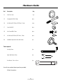
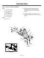
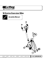
10 Series Exercise Bike
Assembly Manual
Nautilus®
001-7213-112008B
Bowflex®
Schwinn® Fitness
StairMaster®
Universal®
Nautilus Institute®
Table of Contents
Product Specifications.........................................................................2
Safety Warnings.....................................................................................3
Exploded Drawing..................................................................................4
Parts List..................................................................................................5
Hardware Guide.....................................................................................6
Assembly Steps......................................................................................6
Contact Information...............................................................................15
Product Specifications
Dimensions
48” L x 20” W x 51” H (122cm x 51cm x 130cm)
Assembled Unit Weight
57.9 lbs (26.3 kg)
Packaged Shipping weight
66 lbs (30 kg)
Workout Area
88” L x 60” W (224cm x 152cm)
Maximum User Weight
275 lbs (125 kg)
2
Assembly Manual
Safety Warnings
This icon means a potentially hazardous situation which, if not avoided, could result in death or serious injury.
Before using this equipment, obey the following warnings:
Read and understand the complete Owner's Manual.
Read and understand all Warnings on this machine.
•
Keep children away from this machine. Watch them closely when near the machine. Moving parts that appear
dangerous to adults may not appear so to children.
•
Consult a physician before starting an exercise program. Stop exercising if you feel pain or tightness in your chest,
become short of breath, or feel faint. Contact your doctor before using the machine again.
•
Examine this machine for loose parts or signs of wear. Pay special attention to the seat, pedals, and crank arms.
Contact Nautilus Customer Service for repair information. Use only genuine Schwinn® replacement parts supplied by
Nautilus.
•
This exercise machine is for consumer users only.
•
Set up and operate this exercise machine on a solid level surface.
•
Do not wear loose clothing or jewelry. This machine contains moving parts.
•
Maximum user weight limit: 275 lb. (125 kg). Do not use if you are over this weight
•
Stabilize the pedals before stepping on them and use caution when stepping off the machine.
•
Keep at least 19.7 inches (0.5 m) on each side of the machine clear. This is the recommended safe distance for access
and passage around and emergency dismounts from the machine.
•
Warn bystanders to keep a safe distance, at least 3 feet (1 m). Do not allow anyone to touch the operator while the
machine is in motion.
•
Keep the foot pedals clean and dry.
•
Do not over exert yourself during exercise. Operate the machine in the manner described in this manual.
3
Assembly Manual
Exploded Drawing
27
30
5
26
6
14
20
14
24
4
19
8
18
19
7
19
18
18
20
2
21
15
13
10
11
12
1
17
16
28
29
25
9
17
3
16
15
Note: Some component images are for general
reference only and may not represent the actual shape
or detail of the part. Assembly is unaffected.
4
Assembly Manual
Parts List
PARTS LIST
Ref.
Description Qty
1
2
3
4
5
6
7
8
9
10
11
12
13
14
15
16
17
18
19
20
21
22
23
24
25
26
27
28
29
30
Main Body Assembly
Front Stabilizer
Rear Stabilizer
Console Mast Handlebar
Console (Computer) Seat Post
Seat Pad
Left Pedal
Right Pedal
Seat Adjustment Knob
Mast Base
Seat Post Cover
M5 x 10mm Round Head Phillips Screw
M10 x 70mm Carriage Bolt
Arc Washer ID 10.5; OD 25mm: T 1.5mm
M10 Acorn Nut
M8 x 15 Hex Screw
Arc Washer ID 8.5mm; OD 22mm; T 1.2mm
Console Mast Wire (middle computer wire)
Main Frame Wire (lower computer wire)
Not Used
Not Used
Handlebar Heart Rate Wire (hand pulse wire)
Crank (pre-installed)
Handlebar Adjustment Knob
M8 x 20mm Hex Screw
Front Stabilizer End Cap (pre-installed)
Rear Stabilizer End Cap (pre-installed)
Handlebar C-Ring (clamp plate)
1
1
1
1
1
1
1
1
1
1
1
1
1
4
4
4
4
4
4
1
1
1
1
1
1
2
2
1
If you are missing items or have damaged components, please contact 800-NAUTILUS (628-8458) for replacements.
5
Assembly Manual
Hardware Guide
Ref.
Description Qty
13
Seat Post Cover 1pc
15
Carriage Bolt M10 x 70mm
4pcs
16
Arc Washer (ID 10.5mm; OD 25mm; 1.5mm)
4 pcs
17
Acorn Nut M10
4pcs
18
Hex Screw M8 x 15mm
4pcs
19
Arc Washer (ID 8.5mm; OD 22mm; 1.5mm)
4pcs
26
Handlebar adjustment knob with texture
1pc
Tools required
Hex Key L 6mm
1pc
Open End Wrench 15mm
1pc
Box Wrench 17mm x 13mm
1pc
You will also need the following tool (not provided):
Phillips Screwdriver
6
Assembly Manual
Assembly
Basic Assembly Principles
Here are a few basic tips that will aid in the assembly process. By using these principles, you can simplify each
process and save yourself extra time and effort.
1. To make the assembly process go faster, gather the pieces you need for each step and thoroughly read the
assembly instructions for that step prior to starting assembly for the step.
2. When attaching two pieces, gently lift and look through the bolt holes to help guide the bolt through the holes.
3. As a general rule, and for all bolts and nuts, turn bolts or nuts toward the right (clockwise) to tighten and left
(counterclockwise) to loosen.
7
Assembly Manual
Assembly Steps
Step 1: Install Front and Rear Stabilizers
1-1: Secure Front Stabilizer (2) and Rear Stabilizer
(3) to Main Body (1) using 2 Carriage Bolts (15), 2
Arc Washers (16), and 2 Acorn Nuts (17) for both
Stabilizers.
Parts:
• #2 - Front Stabilizer (Qty 1)
• #3 - Rear Stabilizer (Qty 1)
• #1 - Main Body (Qty 1)
1-2: Assemble Front Roller facing forward (Figure 1A).
Position Front Stabilizer so arrow on decal is pointing
upwards.
• #15 - Carriage Bolts (Qty 4)
• #16 - Arc Washer (Qty 4)
• #17 - Acorn Nut (Qty 4)
Tools:
• Wrench L17 - L13
2
21
15
1
16
17
17
16
17
3
16
15
2
Figure 1
UP
Sticker
Figure 1A
8
Assembly Manual
Assembly Steps
Step 2: Attach Front Post
2-1: Connect Console Mast Wire (20) to Main Frame Wire
(21).
Parts:
• #20 - Console Mast Wire (Qty 1)
• #21 - Main Frame Wire (Qty 1)
2-2: Attach Console Mast (4) to Main Body (1) using Arc
Washers (19) and Allen Screws (18).
• #4 - Console Mast (Qty 1)
• #19 - Arc Washer (Qty 4)
• #18 - Hex Screw M8 x 15 (Qty 4)
Tools:
• Hex key L6
20
4
19
19
18
18
20
21
1
Figure 2
9
Assembly Manual
Assembly Steps
Step 3: Connect Console Assembly
3-1: Connect Console Mast Wire (20) top connector on the
back of the Console. Push connected console wires
down into the hole in the top of the Console Mast (4).
Parts:
• #20 - Console Mast Wire (Qty 1)
• #6 - Console Assembly (Qty 1)
• #14 - Phillips Screws (Qty 4)
Note: Do not cut or pinch the wires.
Tools:
3-2: P
lace the Console Assembly (6) on the Console Mast
(4) flat plate (Figure 3A). Secure Console to plate
(Figure 3B) using four Phillips Screws (14).
• Hex key L6
• Phillips screwdriver
6
6
20
20
14
4
Figure 3A
4
14
Figure 3
Figure 3B
10
Assembly Manual
Assembly Steps
Step 4: Connect Contact HR and Handle Bar
4-1: Using C-ring (30), Hex Screw (27) and Knob (26),
secure Handle Bar (5) to Console Mast (4). Tighten
the Adjustment Knob so that the Handlebar is
stable and does not move when pressed.
Parts:
• #24 - Heart Rate Wire (Qty 1)
• #5 - Handlebar (Qty 1)
• #30 - C-Ring (Qty 1)
• #27 - Hex Screw M8 x 20 (Qty 1)
4-2: Connect Heart Rate Wire (24) to the female jack
(Pulse Input) located on the back of the Console (6)
as shown in Figure 4A.
• #26 - Adjustment Knob (Qty 1)
Tools:
• Hex key L6
Pulse
Input
24
26
17
5
30
Figure 4A
6
C-R
ing
To
Fro
n
tP
os
24
t
4
Figure 4
11
Assembly Manual
Assembly Steps
Step 5: Attach Seat Post and Seat
Parts:
5-1: S
lide Seat Post Cover (13) over Seat Post (7).
Pull out Quick Release Knob (11) and insert Seat
Post (7) into Main Body (1). Adjust seat height
and lock into position with Quick Release Knob
(11).
• #13 - Seat Post Cover (Qty 1)
• #7 - Seat Post (Qty 1)
• #8 - Seat Pad (Qty 1)
Tools:
5-2: I nstall Seat Pad (8) on Seat Post (7) and tighten
the nut under the pad to secure the seat.
• Wrench L17-L13
8
7
11
13
1
Figure 5
12
Assembly Manual
Assembly Steps
Step 6: Attach Pedals to Cranks
6-1: Install the Left Pedal (9) to Left Crank (25). Install
Right Pedal (10) to the Right Crank.
Parts:
• #9 - Left Pedal (Qty 1)
• #10 - Right Pedal (Qty 1)
Note: T he Left Pedal has a left handed thread and
screws into the Left Crank counterclockwise.
• Batteries
Tools:
6-2: I nsert C batteries into the back of the Console (6) as
indicated in the battery bay.
• Wrench L15
10
9
25
Figure 6
13
Assembly Manual
Assembly Steps
Step 7: Final Inspection
7-1: Tighten all hardware.
7-2: Read warnings on machine.
Please read and refer to the Owner’s Manual for:
•
Operating Instructions
•
Maintenance Instructions
•
Warranty Information.
Failure to visually check and test assembly before use can cause damage to the equipment.
It can also cause serious injury to users and bystanders.
14
Assembly Manual
Contact Information
UNITED STATES OFFICES:
INTERNATIONAL OFFICES:
E-mail: [email protected]
For technical assistance and a list of distributors in your
area, please call or fax one of the following numbers.
TECHNICAL/CUSTOMER SERVICE
Phone: 800-NAUTILUS (800-628-8458)
Fax: (877) 686-6466
E-mail: [email protected]
INTERNATIONAL CUSTOMER SERVICE
Nautilus International S.A.
Rue Jean Prouvé
1762 Givisiez / Switzerland
Tel: (41) (26) 460 77 77
Fax: (41) (26) 460 77 70
E-mail: [email protected]
CORPORATE HEADQUARTERS
Nautilus, Inc.
World Headquarters
16400 SE Nautilus Drive
Vancouver, Washington, USA 98683
Phone: (800) NAUTILUS (800) 628-8458
GERMANY and AUSTRIA
Nautilus Deutschland GmbH
Albin-Köbis-Str. 4
51147 Köln
Tel.: (49) 02203 2020 0
Fax: (49) 02203 2020 45 45
CANADA OFFICE:
Nautilus Fitness Canada, Inc.
925 Keewatin Street
Winnipeg, MB, Canada R2X 2X4
Phone: (866) 381-5996
Fax: (800) 532-6934
E-mail: [email protected]
ITALY
Nautilus Italy S.r.l., Via della Mercanzia, 103
40050 Funo di Argelato - Bologna
Tel: (39) 051 664 6201
Fax: (39) 051 664 7461
SwITZERLAND
Nautilus Switzerland SA
Rue Jean-Prouvé 6,
CH-1762 Givisiez
Tel: (41) 026 460 77 66
Fax: (41) 026 460 77 60
United Kingdom
Nautilus UK Ltd
Nautilus UK, 4 Vincent Avenue,
Crownhill, Milton Keynes, Bucks, MK8 0AB
Tel: (44) 1908 267 345
Fax: (44) 1908 567 346
chinA
Nautilus Representative Office
Nautilus, Shanghai, 7A No.728, Yan’an Rd(West)
200050 Shanghai, China
Tel: (86) 21 523 707 00
Fax: (86) 21 523 707 09
15
Assembly Manual
©2008. Nautilus, Inc. All rights reserved. Nautilus, the Nautilus Logo, Universal, Bowflex, StairMaster, Nautilus Institute and Active Series are either registered trademarks or trademarks of
Nautilus, Inc. Schwinn and the Schwinn Quality Seal are registered trademarks. All other trademarks are owned by their respective companies.
Nautilus, Inc., World Headquarters, 16400 SE Nautilus Drive, Vancouver, WA 98683 1-800-NAUTILUS www.nautilus.com
Printed in China
Nautilus®
Bowflex®
Schwinn® Fitness
StairMaster®
Universal®
Nautilus Institute®