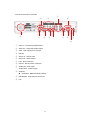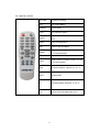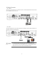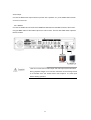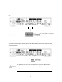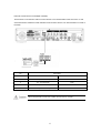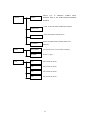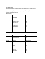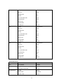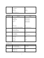
1
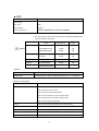
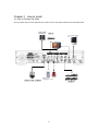
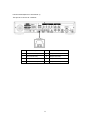
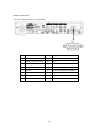
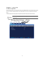
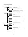
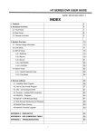
1
Introduction
Thank you for purchasing the SVR440
This user manual is for the SVR-440. The term “unit” always refers to the SVR-440. We
recommend users who install and operate the unit to thoroughly read this manual and other
reference manuals indicated in this manual before installation and operation.
This specification is subject to changes without prior notice to incorporate improvements in the
performance of the unit.
Warranty and Disclaimer
The manufacturer does not assume any responsibilities related to the sales of the unit and does
not endorse any third party to represent the manufacturer in anyway. The warranty does not
apply to malfunctions of the unit or its parts resulting from any accident, negligence, misuse, or
misapplication. Also, the warranty does not include accessories or components that the
manufacturer does not supply.
The warranty is valid for the two years from the date of purchase. However, the malfunctions
listed below are not covered by the warranty even during the warranty period. Repair services
for the malfunctions below will be available, but with applicable charges.
. If any malfunctions occur due to carelessness of the user;
. If a user disassembles or replaces any parts of the unit without permission;
. If any power other than the rated power is connected to the unit;
. If malfunctions occur due to natural disaster (fire, flood, tidal wave, etc.); or,
. If consumable parts/items are to be replaced;
The warranty specified herein is only for the units delivered.
Consumers will be charged for examination and repairs after the expiration of the warranty period
(2 years). A fee will be assessed for repairs or examination except within the scope of warranty
specified herein even during the warranty period.
For out-of-warranty services, please contact your local vendor or service center.
※ But, Consumptive parts such as HDD exclude from free quality guarantee.
2
Warning Marks
Warnings and Cautions – the marks that give warning to users in this manual indicate different levels
of importance. These marks are classified by the level and potentiality of risk.
It is strongly recommended for users to completely understand these marks before using the unit.
This warning is given where carrying out an instruction can cause serious risk of
injury or death if the unit is not properly handled or operated. It indicates the
operations requiring the highest attention in handling or operating the unit.
.
This warning is given where carrying out an instruction can cause risk of damage to
the equipment or minor injury if the unit is not properly handled or operated. It
indicates the operations requiring the proper attention in handling or operating the
unit.
It provides references or information that may be helpful to users in operating the
Unit.
WEEE (Waste Electrical and Electronic Equipment)
Customers in European Union countries are advised to dispose of this product, at the
end of its useful life, as per applicable local laws, regulations and procedures.
3
Table of contents
CHAPTER 1
SAFETY CAUTIONS.................................................................. 7
CHAPTER 2
OVERVIEW ................................................................................ 9
2.1 Features .................................................................................................................................................9
2.2 Configuration...................................................................................................................................... 11
2.3 Names and Functions of Each Part...................................................................................................12
2.3.1 Control Panel on the front .............................................................................................................12
2.3.2 Rear Connection Terminals .........................................................................................................14
2.3.3 Remote Controller .........................................................................................................................15
2.4 Unit Specification ...............................................................................................................................16
CHAPTER 3
HOW TO INSTALL................................................................... 21
3.1 How to Connect All Parts ..................................................................................................................21
3.2 Detailed Connection ...........................................................................................................................22
3.2.1 Camera...........................................................................................................................................22
3.2.2 Audio .............................................................................................................................................22
3.2.3 Monitor..........................................................................................................................................23
3.2.4 External Connector ........................................................................................................................24
CHAPTER 4
HOW TO SET........................................................................... 28
4.1 Menu Configuration...........................................................................................................................28
4.2 Default Setup.......................................................................................................................................31
4.3 Menu Screen Setup.............................................................................................................................34
4.4 SCREEN SETUP ................................................................................................................................35
4.4.1 CH1~CH4......................................................................................................................................36
4.4.2 AUTO SEQUENCE ......................................................................................................................37
4.4.3 STATUS DISPLAY ......................................................................................................................37
4
4.5 RECORD SETUP...............................................................................................................................38
4.5.1 REPEAT RECORD .......................................................................................................................38
4.5.2 RECORD SETUP..........................................................................................................................39
4.5.3
CH1~CH4...................................................................................................................................39
4.6 SYSTEM SETUP................................................................................................................................41
4.6.1 HDD FORMAT.............................................................................................................................41
4.6.2 PASSWORD .................................................................................................................................41
4.6.3 CLOCK .........................................................................................................................................42
4.6.4 ETC(LANGUAGE SETTING) .....................................................................................................42
4.7 NETWORK & SERIAL SETUP.......................................................................................................43
4.7.1 NETWORK ...................................................................................................................................43
4.7.2 CLIENT ACCESS.........................................................................................................................50
4.7.3 SEND E-MAIL..............................................................................................................................50
4.7.4 RS-485/422....................................................................................................................................51
4.8 EVENT SETUP ..................................................................................................................................51
4.8.1 MOTION DETECTTION .............................................................................................................52
4.8.2 SENSOR TYPE.............................................................................................................................53
4.9 PTZ SETUP ........................................................................................................................................53
4.9.1 Setup by Channel...........................................................................................................................53
4.10 EXIT MENU .....................................................................................................................................54
4.11 ETC....................................................................................................................................................54
4.11.1 Firmware Upgrade.......................................................................................................................54
4.11.2 Solution for time mismatch .........................................................................................................55
CHAPTER 5
OPERATIONS.......................................................................... 57
5.1 Preliminary Checks before Starting Operation...............................................................................57
5.2 Power Connection...............................................................................................................................57
5.3 Live Video Screen ...............................................................................................................................58
5.3.1 Single and Multi Channel Display.................................................................................................58
5.3.2 Auto Screen Display Switching.....................................................................................................58
5
5.4 Recording ............................................................................................................................................59
5.4.1 General Recording.........................................................................................................................59
5.4.2 Scheduled Recording.....................................................................................................................59
5.5 Recorded Video Search......................................................................................................................59
5.5.1 EVENT SEARCH .........................................................................................................................60
5.5.2 TIME LINE BAR ..........................................................................................................................60
5.5.3 GO TO...........................................................................................................................................61
5.5.4 GO FIRST .....................................................................................................................................61
5.5.5 GO LAST ......................................................................................................................................61
5.5.6 LOG FILE LIST ............................................................................................................................61
5.5.7 COPY LIST ...................................................................................................................................62
5.6 Recorded File Playback .....................................................................................................................64
5.7 PTZ ......................................................................................................................................................64
5.7.1 PAN/TILT adjustment...................................................................................................................64
5.7.2 ZOOM/FOCUS adjustment ...........................................................................................................64
5.7.3 INITIALIZE ..................................................................................................................................65
CHAPTER 6
NETWORK VIEWER PROGRAM ............................................ 66
6.1 Network Viewer Program Installation .............................................................................................66
6.1.1 System Requirement......................................................................................................................66
6.1.2 Network Environment ...................................................................................................................66
6.1.3 Program Installation ......................................................................................................................66
6.2 Control Panel for Live screen............................................................................................................68
6.3 Control Panel for Live screen............................................................................................................72
6.4 control Panel for Search screen.........................................................................................................79
6.5 Other Search Button ..........................................................................................................................81
6.6
Search ...............................................................................................................................................82
CHAPTER 7
TROUBLESHOOTING ............................................................. 83
6
Chapter 1
Safety Cautions
* Before Installation
– On the rear of the unit, ensure accurate setting of supply voltage prior to power connection.
– Disconnect the power before installation.
– Do not install the unit in humid locations. It may result in a risk of electrical shock or fire.
– This unit must be properly grounded to prevent any risks of electrical shock.
* During Operation
– Do not open the cover of the unit unless you are an authorized installer. It may result in a risk of
electric shock.
– Operate the unit within the allowable limits of temperature and humidity.
– Do not connect several power lines to one outlet at the same time. It may result in a risk of fire.
– Do not put heavy objects or containers of water or other liquid on the unit. It may result in failure
of the unit.
– Do not use near flammable gases or combustible dusts such as propane or gasoline. It may
result in a risk of explosion or fire.
– Do not touch power plug with wet hands. It may result in a risk of electrical shock.
– Random replacement of built-in lithium battery by other types of batteries may cause explosion.
Thus, the battery shall be replaced by the same battery. And the used batteries shall be disposed
carefully because they can cause environment pollutions.
– Be careful to prevent any electrified materials from being absorbed through the ventilation grilles
of the cooling fan.
– Do not forcefully drag a power cord. It may result in a risk of electric shock or fire if a cord is
damaged.
* Disassembly and Cleaning
– Do not disassemble, repair, or alter the unit without authorization. It may result in a risk of failure,
electrical shock, and personal injury.
– Do not use water, thinners, or organic solvents for cleaning the unit surface. It may result in a risk
of failure or electrical shock. For cleaning the unit surface, use a dry cloth.
7
* During Installation
– Install the unit such that a minimum of 15cm space exists between the ventilation grills of the
cooling fan and any wall or surface in order to ensure smooth heat release.
– Be sure to install the unit on the flat surface. An unsecured fall may result in a risk of failure or
personal injury.
– Keep away from the direct sunlight or excessive heats. It may result in a risk of distortion or failure
of the unit.
– If a camera is installed during the DVR recording, the images of other channels can be broken.
We recommend to start recording after installation of a camera.
* During Operation
– Be cautious not to shock or shake the unit while moving or operating the unit.
– Do not move the unit while it is in use.
– Do not apply strong force or throw the unit.
– We recommend using SAMSUNG/Western Digital/Maxtor HDD(7200RPM / EIDE Type)If you add
other HDDs, the system may cause abnormal operations. Thus, please contact your local vendor
before adding a HDD. The unauthorized addition of HDD shall not be subject to the warranty.
FCC Compliance Statement
. Caution:
Any changes or modifications in construction of this device which are not expressly
approved the party responsible for compliance could void the user’s authority to
operate the equipment.
. NOTE:
This equipment has been tested and found to comply with the limits for a Class A digital
device, pursuant to part 15 of the FCC Rules. These limits are designed to provide
reasonable protection against harmful interference when the equipment is operated in a
commercial environment. This equipment generates, uses, and can radiate radio
frequency energy and, if not installed and used in accordance with the instruction manual,
may cause harmful interference to radio communications, Operation of this equipment in
a residential area is likely to cause harmful interference in which case the user will be
required to correct the interference at his own expense.
8
Chapter 2
Overview
The Samsung SVR-440 is a digital video recorder designed to be used as the security device in
small shops, convenience stores, banks, ATMs, etc. It is a stand-alone device, securing system
performance and safety. The Samsung SVR-440 saves video images on the HDD instead of on
videotapes. Then, it can save quality images even for repetitive recording and facilitates data search
as recording and playing video data in the digital file format. Moreover, the Samsung SVR-440 is a
user-oriented digital unit with high quality moving pictures and high capacity storage media. It has a
variety of functions such as motion detects, PTZ (Pan, Tilt and Zoom) control, password setting, realtime voice data storage, and event lists and log file storage.
2.1 Features
Monitoring Screen
The Samsung SVR-440 implements high quality live images every channel and provides a wide
range of monitoring screens.
. Real-Time Full Screen and Split Display Mode
. Auto Screen Display Switching(AUTO)
. Pan &Tilt control
Recording
The Samsung SVR-440 can record up to 120 frames per second. It also records events on an event
list as well as provides the pre-event recording function.
. Simultaneous execution of three functions: recording, playback, and networking
. Convenient setting of recording resolution by channel.
. Up to 3 kinds of image quality setting available.
. Simple setting of the scope of motion detection.
. Recording setting up to 120 frames per seconds.(based on 360X240)
. Manual and schedule recording.
. Event recording using external alarms and motion detection function.
. Creating event lists for external alarms and motion detection.
. Recording images before the occurrence of events.
Playback
. Playback by time, date, and channel.
. Still image search.
. Convenient search using a remote control
9
Storage Media
Built-in HDD is the basic memory supply. Using USB memory stick or External CD-RW((Guaranteed
to the recommended model only), Users can copy the images on it from the internal HDD.
. Basic Memory Supply: Built-in HDD
. backup media: : USB memory stick
External CD-RW – Maker : LITEON CO., LTD
Model : LTR-52327SX
Network
The Samsung SVR-440 supports a wide range of networks such as LAN and ADSL, DHCP. The user
can also easily operate and manage main functions of the unit from a remote place using the
exclusive PC viewer.
. Live image view from a remote location available (full or quad screen mode selectable).
. Search and playback by time or event from a remote location.
. 10/100Mbps Ethernet/xDSL supported.
. DDNS supported.
Others
. Simple firmware upgrade using USB memory.
. Up to 4 channel voice recording in real time
. VGA output supported
. Languages for menus – selectable.
10
2.2 Configuration
The SVR-440 package contains the main unit and its components as specified below. When you
purchase the unit, please check to ensure the components specified below are included. If any
components are missing, please contact your local vendor.
SVR-440 Main Unit
1. Network viewer program CD
2. User Manual
4. Battery for Remote control
5. Adapter
3. Remote Control
6. Power Cable
Following parts will be included when HDD is not installed.
7. HDD IDE Cable
8. HDD Plate
11
6. Rubbers and screws for HDD
2.3 Names and Functions of Each Part
2.3.1 Control Panel on the front
Indication LED
LED Name
Description
Power
Light up when power is applied to the system
HDD
Light up when the system is accessing HDD
EVENT
NETWORK
Light up when sensor is triggered or Motion is detected
Light up when client has connected to the system through the
network
REC
Light up when the system is recording video data
Functional Button
Button Name
AUTO
Description
Press to start Auto Sequence
SEARCH
Press to search the recorded data
COPY
Press to backup still image or video
PTZ
Press to control PTZ camera
MENU
Press to launch Setup Menu
REC
PLAY/PAUSE
Press to start and stop recording
Press to Play and pause the Playback screen
Backward Playback. Speed at 1X, 2X, 4X
Jump Backward. Playback position moves 1 minute backward
Jump Forward. Playback position moves 1 minute forward
Forward Playback. Speed at 1X, 2X, 4X
ESC
Press to return to previous Menu screen
Press to move up in Menu item in setup mode and to select camera1
in live mode. It can also be used to enter number 1 when entering
password.
12
Press to move right in Menu item in setup mode and to select camera2
in live mode. It can also be used to enter number 2 when entering
password.
Press to move down in Menu item in setup mode and to select
camera3 in live mode. It can also be used to enter number 3 when
entering password.
Press to move left in Menu item in setup mode and to select camera4
in live mode. It can also be used to enter number 4 when entering
password.
Press to select full screen or quad screen in live monitoring mode. It
can also be used to select desired menu item or to store the setup
value in the menu.
USB PORT
USB Backup and Firmware upgrade
13
2.3.2 Rear Connection Terminals
⑬
⑦
①
⑨
⑫
⑤
⑥
④
⑩
②
③
⑧
⑪
①
Video in : Camera Input(NTSC/PAL)
②
Video out : Composite Video Output
③
VGA : VGA output for PC monitor
④
RS-232
⑤
Sensor in : Sensor Input
⑥ Alarm out : Alarm Output
⑦
LAN : RJ45 connector
⑧
DC12V : DC12V Power connector
⑨ AUDIO IN : Audio Input
⑩ AUDIO OUT : Audio Output
⑪
Switches
NTSC/PAL, BNC/VGA Select Switch
⑫
RS-485/422 : PTZ Camera control use
⑬
Fan
14
2.3.3 Remote Controller
RECORD
Start/Stop Recording
PTZ
PTZ Control Button
SEARCH
Search Button
AUTO
Auto Sequence button
Select and Save the changed value in
ENTER
Menu
MENU
Enter into Setup Menu
ESC
Return to previous Menu
Jump backward. Playback position moves
F/REW
to 1 minute backward.
Playback/Pause in Playback mode
PLAY/PAUSE
Jump Forward. Playback position moves
F/ADV
to 1 minute forward.
REW
Backward Playback. Speed at 1x, 2x, 4x
COPY
Backup button
FF
Forward Playback. Speed at 1x, 2x, 4x
0~9
Remote control ID setup from 0 to 9.
15
2.4 Unit Specification
■ System
Items
Specification
Processor
DSP
Operating System(O/S)
RTOS
Compression method
MPEG-4
■ Video
Items
Specification
Input Method
Composite Input 4-Channel
Video Input Level
1.0 Vp-p, Composite
Live Screen Display Speed
NTSC:
120 Frames/Sec
PAL:
Live Screen Digital Memory
100 Frames/Sec
NTSC: 720 (W) _ 480 (H) Pixels for the full screen.
PAL: 720 (W) _ 576 (H) Pixels for the full screen
8bit Brightness (256 Gray Scales)
24bit Colors (160,000 Colors)
Monitor Output
1.0Vp-p Composite, 75Ω
VGA Output (PC Monitor)
RGB Output(Non Interlaced Scan)
* Select composite or VGA
■ Audio
Items
Audio
Specification
4CH Audio Input
1CH Audio Output
Audio Compression
ADPCM
■ Alarms
Items
Specification
Input
4 Channel
Output
1 Relay output(Motion detect, Alarm), user configurable
16
■ Remote Control
Items
Specification
Infrared LED
Up to 5m
■ Recording
Items
Specification
Maximum Number of Frames/Sec
NTSC(720X480):
30 Frames/Sec
(Resolution)
NTSC(360X240):
120 Frames/Sec
PAL(720X576):
25 Frames/Sec
PAL(360X288):
100 Frames/Sec
Recording Method
3 Types of Recording Modes: General, Schedule, Event
Pre-Event Recording
Channel ON/OFF Setting
Image Quality
3-Stage Image Quality: User Configurable
.
Countries using NTSC: USA, Canada, Japan, Korea, Taiwan, Mexico, etc.
Countries using PAL: Australia, Austria, Belgium, China, Denmark, Finland,
Germany, UK, Netherlands, Italy, Kuwait, Malaysia, New
Zealand, Singapore, Sweden, Spain, Switzerland, Thailand,
Norway, etc.
17
■ HDD
Items
Specification
Basic Supply
1
HDD Type
EIDE
Minimum Rate
7200rpm
Recommended units
Western Digital/Samsung Electronics/Maxtor
We recommend the models described below among Western Digital/Samsung
Electronics/ Maxtor HDD series.
Model
HDD Capacity
Buffer
WD1600BB-22GRA0
160GB
2M
WD2000BB-00GUA0
200GB
8M
WD2500BB-00KEA0
250GB
8M
SP0822N
80GB
2M
SP1604N
160GB
2M
Maxtor
7Y250P0
250GB
8M
Seagate
ST3400832ACE
400GB
8M
Hitachi
HDS725050KLAT80
500GB
8M
Western Digital
Samsung
■ Backup
Items
Digital Backup
Specification
USB Memory Stick or External CD-RW(LITEON CO,.LTD LTR-52327SX
■ Search and Playback
Items
Search Mode
Specification
Search by Time: Year, Month, Date, Hour, Minute
Search by Channel: per channel
Search by Event: Alarm, Motion Detect
Search by the first data: The First recording image
Search by the last data: The last recording image
Search by bar: Using the search bar
Log File
Power On/Off, Recording Start/Stop, Information Display
Speed & direction of Playback
Forward and Reverse
Fast Search
Rewind(X2, X4), Rewind (X2, X4)
Jump Search
I minute before and after image
Pause and Frame Playback
Pause of playback, Playback by frame in the pause status
18
■ Password
Items
2 stage Password
Specification
4-digit Password(including four numbers)
Adimin : Control all function(Default is 1111)
Network: : Network access (Default is 1111)
■ Network
Items
General
Specification
Live Screen: Monitoring
Playback Screen: Search
Menu Setting: Menu setting available(CMS S/W : option)
Access Method: Dedicated Viewer
Protocol: TCP/IP, DHCP
Interface:
Ethernet(10/100Mbps), ADSL
Concurrent Users: Up to 4 users
PC Requirement
CPU:
Pentium IV 1.2GHz or over (2.0GHz or over recommended)
Memory:
HDD:
256MB or over (512MB or over recommended)
Minimum 10GB or over
OS: Windows 2000 or over recommended
1,024_768 Pixels
Monitor:
LAN Interface:
10/100 Base–T (RJ–45)
■ Electrical Specification
Items
Adaptor Spec
Specification
Input
: AC100-240V, 50/60Hz , 1.5A
Output :
Power Consumption
DC12V, 5A
About 25W
■ User Environment
Items
Specification
Operating Temperature
5°C ~ 40°C
Storage Temperature
10°C ~ 60°C
Humidity
30%~90%(without dewfall)
19
■ Exterior
Items
Specification
Material
Steel Case
Dimension
260(W) X 350(D) X 65(H)mm
Weight
About 4.5Kg
■ Connection Terminals
Items
Specification
Video Input
BNC(4)
Monitor Output
BNC(1)
VGA Output(PC Monitor)
15-Pin DSUB
Audio Jack
RCA Input(4), RCA Output(1)
USB Port
USB2.0(Firmware Upgrade/Copy)
9-Pin DSUB
RS-232C(Standby)
6-Pin Terminal sector
RS-422/485(External control, PTZ)
8-Pin Terminal sector
Alarm Input Terminal
2-Pin Terminal sector
Alarm Output Terminal(Motion Detect, Sensor: CM, NO, NC)
Termination Switch (JP2 Termination)
RS-422/485 Terminal Resistance Switch (RS-422/485 termination
can be set using jump setting after open the top cover)
LAN Input
RJ-45(Network)
DC Input
DC Power Input
■ Accessories
Items
Accessories to be supplied
Specification
Network Viewer Program CD
User Manual
Remote Control & Battery
Rubbers and screws for HDD plate
Adapter, Power cable
20
Chapter 3
How to Install
3.1 How to Connect All Parts
The connection layout for the SVR-440, the monitor, CCTV and external devices are described below.
3.2 상세 연결
3.2.1 착탈식 하드디스크 랙 장착 방법
21
3.2 Detailed Connection
3.2.1 Camera
SVR-440 can accommodate up to 4 cameras for CCTV. Connect the BNC terminal of each camera
to the CAMERA IN terminal of the unit.
3.2.2 Audio
The Samsung SVR-440 can save audio information. For storage or output of audio information, it is
required to connect the relevant devices.
_
- For Audio input setting, set [Audio] to [ON] on the Recording setting menu.
- When playback with audio in split display mode is not working properly, turn the
display mode to Full screen to avoid an audio playback problem.
22
Audio Output
Connect the RCA Audio Output Terminal (monitor with a speaker, etc.) to the AUDIO OUT terminal
on the rear of the unit.
3.2.3 Monitor
Connect the VIDEO OUT terminal of the MONITOR OUTPUT and the BNC terminal of the monitor
using the BNC cable for video data output to the main monitor. There is also VGA video output for
the PC monitor.
User can not use both of Video output and VGA output at the same time.
During playback images on PC monitor, few frame can be missing but this
is not a defect of the unit. Please refer to the Chapter 5. 5.1 Check point
before Starting operation.
23
3.2.4 External Connector
Alarm Input(ALARM IN)
This external sensor connection terminal transfers data from the connected sensor or device to the
unit.
Relay Output(RELAY OUT)
This Alarm Output terminal uses the contact relay for the alarm output to the external devices. You
can select NO (Normal Open), CM (Common) or NC (Normal Close) for connection according to the
contact point status.
The operation of each relay output can be defined by a combination of Motion Detect,
Sensor in the Event Setting on the Main Menu. See Paragraph ‘4.5.3 CH1~CH4’ Relay
Setting for details
24
External Control Device Terminal(RS–422/485)
This terminal is connected to external control devices. The JP2 termination that set is turns on and
off the termination resistance of RS–422/485 communication device. The JP2 termination is inside of
the DVR.
`
No.
Classification
Description
RS-422
RS-485
1
TX+(+Transmit Data)
Data+
2
TX-(- Transmit Data)
Data-
3
RX+(+Receive Data)
4
RX-(- Receive Data)
When using RS–485, connect TX+ to Data+ and connect TX– to Data–.
25
LAN Connection(Ethernet 10/100 Base–T)
This port is to connect to a network.
No.
Description
No.
Description
1
TX+(Transmit Data)
5
N/C(No connection)
2
TX-(Transmit Data)
6
RX-(Receive Data)
3
RX+(Transmit Data)
7
N/C(No connection)
4
N/C(No connection)
8
N/C(No connection)
26
Monitor Output(VGA)
This is the output connector for VGA Monitor.
No.
Description
No.
Description
1
Red Signa(75, 0.7Vp–p)
9
N/C(No connection)
2
Green Signal(75, 0.7Vp–p)
10
Ground
3
Blue Signal(75, 0.7Vp–p)
11
Ground
4
N/C(No connection)
12
N/C(No connection)
5
Ground
13
HSYNC (Horizontal Synchronization)
6
Ground
14
VSYNC(Vertical Synchronization)
7
Ground
15
N/C(No connection)
8
Ground
27
Chapter 4
How to Set
4.1 Menu Configuration
Press the Menu button on the front side of the unit or the MENU button on the remote control, and the
menu for a variety of settings related to the unit will appear. The menu is configured as described
below.
Screen setup Record setup System setup Network & Serial setup Event setup PTZ Setup
The factory default language is English. See Paragraph 4.10.4 - Other Settings for
Language setup.
28
The menu is configured as illustrated below.
Main Menu
Screen
Submenu
Setup Subjects
CH1~4
Title, Brightness, Contrast
Auto Sequence
Sequence, Sequence Dwell, Video Loss Skip
Status
OSD, Clock Display, HDD Free Space, Recording Status,
Title Display, Event Display, OSD Contrast
Record
Repeat
Record
CH1
Repeat Record, Warning Massage, Warning Beep
IImage Size
Mode, Quality, Frame Rate, Audio, Post Record Time, Pre
Record, Relay Out, Event Beep, Schedule
Mode, Quality, Frame Rate, Audio, Post Record Time, Pre
CH2
Record, Relay Out, Event Beep, Schedule
Mode, Quality, Frame Rate, Audio, Post Record Time, Pre
CH3
Record, Relay Out, Event Beep, Schedule
Mode, Quality, Frame Rate, Audio, Post Record Time, Pre
CH4
Record, Relay Out, Event Beep, Schedule
System
HDD Format
Format
Password
Admin Password, Network password
Colock Setup
Clock, Date Mode, Month Type
ETC
Language, Key Buzzer, Default, Discription, Remote
controller ID
29
Network
Network
Network
Type,
IP
ADDRESS,
SUBNET
GATEWAY, DNS, ID, PW, DDNS SERVER DONAMAIN
ADDRESS
PORT, CLIENT ACCESS, BANDWIDTH SAVING
Client Access
E-mail, Mail Address, Mail Server IP
E-Mail
System ID, BAUD RATE, DATA BIT, PARITY BIT,
RS-485/422
STOP BIT
Event
PTZ
MASK,
Motion Detect
CH1~4 Motion Zone, CH1~4 Motion Sensitivity
SENSOR
Sensor 1~4 Type
CH1
PTZ Camera ID, Model
CH2
PTZ Camera ID, Model
CH3
PTZ Camera ID, Model
CH4
PTZ Camera ID, Model
30
4.2 Default Setup
The SVR-440 is delivered to customers with the factory default values as described below. To
initialize the menu setup to the factory default values, select [YES] for the [DEFAULT] item in
[SYSTEM SETUP]–[ETC] on the menu. Then, all setting values changed by users are initialized to
the default values as illustrated below.
■ Screen Setup
Main Menu
CH 1~4
AUTO SEQUENCE
STATUS
Submenu
Default
TITLE
1, 2, 3, 4
BRIGHTNESS
0
CONTRAST
0
SEQUENCE
OFF
SEQUENCE DWELL
1SEC
VIDEO LOSS SKIP
OFF
OSD
ON
CLOCK DISPLAY
ON
HDD FREE SPACE
ON
RECORD STATUS
ON
TITLES DISPLAY
ON
EVENT DISPLAY
ON
OSD CONTRAST
90%
■ Record Setup
Main Menu
REPEAT
Submenu
Default
REPEAT RECORD
ON
WARNING MASSAGE
1%
WARNING BEEP
OFF
RECORD
IMAGE SIZE
360x240(360x288)
CH1
MODE
CONTINUOUS
QUALITY
HIGH
FRAME RATE
1f/s
AUDIO
OFF
POST RECORD TIME
5SEC
PRE RECORD
5SEC
RELAY OUT
OFF
EVENT BEEP
OFF
SCHEDULE
SETUP
31
CH2
CH3
CH4
MODE
CONTINUOUS
QUALITY
HIGH
FRAME RATE
1f/s
AUDIO
OFF
POST RECORD TIME
5SEC
PRE RECORD
5SEC
RELAY OUT
OFF
EVENT BEEP
OFF
SCHEDULE
SETUP
MODE
CONTINUOUS
QUALITY
HIGH
FRAME RATE
1f/s
AUDIO
OFF
POST RECORD TIME
5SEC
PRE RECORD
5SEC
RELAY OUT
OFF
EVENT BEEP
OFF
SCHEDULE
SETUP
MODE
CONTINUOUS
QUALITY
HIGH
FRAME RATE
1f/s
AUDIO
OFF
POST RECORD TIME
5SEC
PRE RECORD
5SEC
RELAY OUT
OFF
EVENT BEEP
OFF
SCHEDULE
SETUP
■ SYSTEM SETUP
Main Menu
Submenu
Default
HDD
HDD FORMAT
FORMAT
PASSWORD
ADMIN PASSWORD
SETUP
NETWORK PASSWORD
SETUP
CLOCK
SETUP
DATE MODE
YY/MM/DD
MONTH TYPE
INITIAL
CLOCK SETUP
32
ETC
LANGUAGE
ENGLISH
KEY BUZZER
OFF
DEFAULT
SETUP
DESCRIPTION
DISPLAY
REMOTE CONTROLLER ID
0
■ NETWORK
Main Menu
NETWORK
CLIENT ACCESS
E-MAIL
RS-485/422
Submenu
Default
NETWORK TYPE
LAN
IP ADDRESS
000.000.000.000
SUBNET MASK
000.000.000.000
GATEWAY
000.000.000.000
DNS
000.000.000.000
ID
-
PW
-
DDNS SERVE
OFF
DDNS SERVER DOMAIN ADDRESS
ns.standalone4ch.com
PORT
3495
CLIENT ACCESS
ON
BANDWIDTH SAVING
ON
E-MAIL
OFF
MAIL ADDRESS
SETUP
MAIL SERVER IP
211.174.110.134
SYSTEM ID
0
BAUD RATE
9600
DATA BIT
8
PARITY BIT
NONE
STOP BIT
1
■ EVENT SETUP
Main Menu
MOTION DETECT
SENSOR
Submenu
Default
CH1~4 MOTION ZONE
FULL ZONE
CH1~4 MOTION SENSITIVITY
7
SENSOR1 TYPE
OFF
SENSOR2 TYPE
OFF
SENSOR3 TYPE
OFF
33
SENSOR4 TYPE
OFF
■ PTZ SETUP
Main Menu
CH1
CH2
CH3
CH4
Submenu
Default
PTZ CAMERA ID
0
MODEL
NONE
PTZ CAMERA ID
0
MODEL
NONE
PTZ CAMERA ID
0
MODEL
NONE
PTZ CAMERA ID
0
MODEL
NONE
4.3 Menu Screen Setup
Select the MENU button on the remote control or the main unit, and the following Menu Screen
appears.
Main Menu
Sub Menu
Setup items
How to set
Press the MENU button, and the background screen is switched to the Split 4 screen.
. Main Menu: Select the Main Menu corresponding to each Tab.
. Submenu: Select the Submenu that can be set up on the Main Menu.
34
. Setup Items: Change the settings on the Submenu.
. How to Set: This message provides the guide for menu setup.
. It may take a little while for the recording setup. Then, please wait for a while.
. Except for the recording setup, setting changes are immediately applied.
Operations
* Operation the unit using the buttons on the main unit.
- Move between Menus : Press the Arrow
- Change Setting Values: Press the
buttons.
Buttons.
- Exit from Menu Screen: Press the ESC Button.
* Operation using the Remote Control
- Move between Menus to Left/Right: Press the Arrow
- Change Setting Values: Press
buttons..
Buttons.
- Exit from Menu Screen: Press the ESC Button.
4.4 SCREEN SETUP
Press the MENU button and select the Tab by using the Left/Right arrow button, and the submenu
related to the live monitoring screen appears as illustrated below. Press
submenus by using the Left/Right arrow button. Next, press
setup items by pressing the Up/Down button.
35
button and select the
button again, and you can select
4.4.1 CH1~CH4
Select setup items related to channels such as channel titles or brightness.
. Channel Titles: Titles can be individually set to each channel. Select the channel title and press
ENT button. Then, the keyboard to enter the title is displayed as illustrated below.
The positions of characters in the Channel Titles can be arranged by using
buttons.
- After moving the cursor, is moved, press the ENT button to select the relevant character.
- To exit from the Menu Setup, press the ESC button.
- Press the Up/Down arrow button to move between character strings.
- To insert spaces, move the cursor to SPACE on the screen and then press SELECT on the
remote control or ENT button the main unit.
. BRIGHTNESS: Adjusts the screen brightness by changing the values.
. CONTRAST: Adjusts the screen contrast by changing the values.
36
4.4.2 AUTO SEQUENCE
The live screens are automatically switched in the order of <CH1 -> CH2 -> CH3 -> CH4 >
at the predefined switching interval. The channel switching interval can be set from 1 up to 10
on the [SEQUENCE] menu.
. SEQUENCE : Set it ON for Auto Sequence mode
. SEQUENCE DWELL: Set the screen display duration by channel. switching interval can be set
from 1 up to 10 sec.
. VIDEO LOSS SKIP : With Video-Loss Skip [ON], channels without video input signals are
automatically skipped and only channels with video input are displayed.
4.4.3 STATUS DISPLAY
Selects information to display on the live screens.
. OSD [ON/OFF] : With OSD[ON], the Status information is displayed on the live screen.
. CLOCK DISPLAY [ON/OFF]: With Clock Display [ON], the current time is displayed on the live
screens.
.HDD FREE SPACE [ON/OFF]: With HDD Free Space [ON], the free space on the HDD for
37
recording is indicated.
. RECORD STATUS [ON/OFF]: With Record Status [ON], the recording status “S” is displayed on
the corner of the screen during recording.
. TITLE DISPLAY [ON/OFF]: With Titles Display [ON], the titles of [CH1 ~ 4] set on the Channel
Title submenu by uses are displayed on the live screens.
. EVENT DISPLAY [ON/OFF]: With Event Display [ON], the event information is displayed when
event is occurred.
. OSD CONTRAST : Set the contrast for Menu OSD. Number of % is higher, the OSD is Darker.
4.5 RECORD SETUP
Press the MENU button and select the Tab using the Left/Right button. Then, the submenu related to
recording appears as illustrated below. Press
Left/Right button. Next, press
button and select the submenu by using the
button again, and you can select setup items using the Up/Down
button.
4.5.1 REPEAT RECORD
Monitoring screens can be recorded on the HDD and the storage capacities vary on HDD types
installed on the unit.
. REPEAT RECORD [ON/OFF]: Set whether to repeat recording.
. ON: If no storage spaces are left on the HDD, recording is continued by overwriting the oldest
data.
. OFF: If no storage spaces are left on the HDD, recording is stopped.
. WARNING MESSAGE: When the remaining capacity of the HDD reaches the predefined
percentage, a warning message is displayed to users. The warning level can be set from
1 to 10%, 5 ~10% in general.
. WARNING BEEP: When the remaining capacity of the HDD reaches the predefined percentage, a
warning beep is activated.
38
4.5.2 RECORD SETUP
. IMAGE SIZE : Set the resolution to either 720X480 or 360X240
4.5.3
CH1~CH4
Set the details of recording setup mode.
39
-
MODE : Select one of four recording methods below.
CONTINUOUS
Continuous recording mode for 24h for day
SCHEDULE
Reserved recording
MOTION DETECT
Recording is activated when the system detects the motion
from input video images.
SENSOR
Recording is activated when the system detects the sensor
operation.
DISABLE
This is a setup mode for not to be recorded
-
IMAGE QUALITY[High/Mid/Low] : Set the compression level for images to be stored
-
FRAME RATE : Set the recording frame rate. 30FPS is the maximum for FULL(720X480)
resolution and 120FPS is the maximum rate for QUAD(360X240) resolution.
-
AUDIO : Select whether to save audio data along with video.
-
POST REC TIME : Recording continues for the predefined hours since the occurrence of an
event. The available setting values are from 1 to 30 seconds.
-
PRE RECORD : This is pre-event record setup. Automatically record 5 second of pre-event
data if you set 5 sec. Pre-event record is not activated if you set OFF.
-
RELAY OUT : Set it ON to activate the relay output.
-
EVENT BEEP : Set it YES to activate the Event beep when the occurrence of an event.
-
SCHEDULE : Press ENT button when the cursor is on SCHEDULE, the schedule setup
screen appears as illustrated below.
Event buzzer will be applied to Ch1 ~ Ch4.
Schedule record can be set 24 hours per day. Press
zone and select the desired record mode by using the ENT button.
C : Continuous recording
S : Sensor recording
40
move to the right time
M : Motion Detect recording
- : Cancel the setting
4.6 SYSTEM SETUP
This is a set up menu related to DVR system. Press the MENU button and select the Tab
using the Left/Right button. Then, the submenu related to system appears as illustrated below. Press
Button and select the submenu using the Left/Right button. Next, press
button again, and you
can select setup items using the Up/Down button.
4.6.1 HDD FORMAT
HDD FORMAT : Select whether to initialize the HDD. Select ON to delete all data saved in the
HDD and the unit will automatically reboot for system stabilization.
4.6.2 PASSWORD
Set the Admin and Network Passwords.
. NETWORK PASSWORD : Network Password is required when access to DVR through
Network and set the 4 digit password using Up/Down and Right/Left button.
. ADMIN PASSWORD : Admin Password is authority for all system setup and consisted by 4
41
digit password using Up/Down and Right/Left button..
4.6.3 CLOCK
Set the date of the unit.
. CLOCK : Set the time in this menu.
The unit will automatically reboot for system stabilization
. DATE MODE : Set the date format. Selects the date format among YY/MM/DD, MM/DD/YY,
DD/MM/YY or YY-MM-DD, MM-DD-YY, DD-MM-YY
. MONTH TYPE : Selects the INITIAL or NUMBER for the month format.
4.6.4 ETC(LANGUAGE SETTING)
. LANGUAGE : Selects a language for the Menu screen. Korean, English is available..
. KEY BUZZER : Selects whether to generate the key sound when pressing the buttons
. DEFAULT : Initializes the setting values of the unit to the factory default values.
. DECRIPTION : Detailed information of the unit such as S/W Version, HDD Capacity, IP
Address, MAC address.
42
. REMOTE CONTROLLER ID : Set the remote control ID. If you select 0, it appears R:A on the
screen and user can control all the DVRs by using only one remote controller
4.7 NETWORK & SERIAL SETUP
This is a set up menu related to Network and RS-485/422.
Press the MENU button and select
the Tab by using the Left/Right button. Then, the submenu related to Network and serial
communication appears as illustrated below. Press
the Left/Right button. Next, press
button and select the submenu by using
button again, and you can select setup items by using the
Up/Down button.
4.7.1 NETWORK
Set the necessary items for network connection to a computer.
. NETWORK TYPE [ADSL/LAN/DHCP] : Selects the network types connected to a computer.
. IP ADDRESS: Enters [IP ADDRESS] that the relevant Internet service provider assigns to a user.
. SUBNET MASK: Enters [SUBNET MASK] address that the relevant Internet service provider
assigns to a user.
. GATEWAY: Enters [GATEWAY] Address that the relevant Internet service provider assigns to a
user.
. DNS: Enters [DNS] address that the relevant Internet service provider assigns to a user.
. ID: Enters a User ID registered within the relevant service provider.
. PW: Enters a User Password registered within the relevant service provider.
. DDNS SERVER ON/OFF: When DVR is connected to dynamic IP, the IP address changes every
time it attempts to connect to ISP. In this case, there is no way for a user
to know the changed IP address. If DVR that uses a dynamic IP address is
registered with its domain name, the domain name can be easily found
and can be connected even if the IP changes.
43
Step 1) user can set DDNS on the set up menu of SVR-440 as below.
Select the Network menu and the following screen is displayed.
Move the cursor on the DDNS SERVER and set it ON.
This is all about the DDNS setup on the DVR unit.
Step 2) Using the IP authentication program, obtain the authentication numbers.
1. “Dynamic IP authentication program” Download
- www.samsungcctv.co.kr SVR-440 Download center Dynamic IP authentication
program Download
2. Check the MAC ADDRESS and Domain name as below.
44
Procedure)
Execution of the Dynamic IP authentication program Write MAC ADDRESS Click on the
button confirm the authentication number!!
Using GEN SERIAL, obtain the Registration number according to the Mac address
Refer to the Mac address from the following path, DVR System setup-ETC-System
info-MAC ADDRESS.
Input the Mac Address on the GEN SERIAL and click on 생성 button to generate the
authentication numbers.
45
Click
Generate authentication number
Input Mac Address
Step 3) Move on to the DDNS registration server once the authentication number is generated.
DDNS server -. http://211.174.110.135 (http://standalone4ch.com)
1. Register the ID and Password to be used for product registration.
Input ID & Password and click on the OK button.
Enter the ID & P/W of the system you wish to register on the DDNS registration server screen. After
entering the ID&P/S, click OK on the lower right corner of the screen. Then the next menu screen will
appear as below.
2. Then the next menu screen or You will see the screen as below. Click Registration to go to the
next menu screen as below.
46
Click..!!
3. Input Mac address, Registration and Domain name. Click on the CHECK button to move on
next step.
Click..!!
4. The following message will be displayed if the Domain name entered is usable.
47
5. The following message will be displayed if the Domain name entered is not
usable.
6. Click on
button and then click on the OK button on Camera & Server registration
screen.
7. Once the registration is done, Click on the LIST button on Camera & Server registration
screen. Registered domain can be checked as below.
8. Domain name can be easily modified. Select the desired host name
and click on the
INFO CHANGE to change the name.
Click..!!
48
9. Mac address can not be modified therefore Click on the DELETE button to delete the host
name and repeat the registration procedure.
Click..!
10. Click on the ‘YES’ button to delete the host name.
Click..!!
49
4.7.2 CLIENT ACCESS
. PORT: When connecting to PC, the ports can be changeable.
To connect SVR-440 to router, it needs to set all 3 kinds of ports.
Default setting port on DVR: Control – Connect, ptz, event and other control data
Default setting port +1: VIDEO
Default setting port +2: AUDIO
For example)Default setting port on DVR: 3495
Setting port for VIDEO: 3496
Setting port for AUDIO: 3497
. CLIENT ACCESS: Set the Network access password.
. BANDWIDTH SAVING: Select Bandwidth Saving ON, Transmit frame rate reduces to 1fps.
4.7.3 SEND E-MAIL
In case of the connected dynamic IP changes, send the new IP address to the registered
E-mail address.
. SEND E-MAIL: Select ON for the E-mail sending.
. MAIL ADDRESS: Press ENT button to display the Key-board screen and select the collect Email address.
50
. MAIL SERVER IP: Please remain the default value.
4.7.4 RS-485/422
Set the connection details between monitoring devices and units. For example, set details between a
camera and a CCTV.
. SYSTEM ID: Set the IDs related to the DVR main unit ID in connecting devices such as cameras
to the unit.
. BAUD RATE: Set the data transfer rate per second.
. DATA BIT: Set the data transfer bit.
. PARITY BIT: Set the error checking method in data transfer.
. STOP BIT: Set the bits to insert when the data transfer is completed.
4.8 EVENT SETUP
Set the submenu as described below for event recording.
51
4.8.1 MOTION DETECTTION
CH1~4 [ON OFF] : Set whether to detect motions by channel.
. Sensitivity : You can set the sensitivity to the changes on a screen from 1 to 9. Higher values mean
more precise motion detection.
. Area Setup : Select the area for the motion detection in FULL or Partial zone.
-
FULL ZONE : Detect motions by analyzing the changes of Full images from cameras.
-
PARTIAL ZONE : User can select the desired zone for motion detect.
52
4.8.2 SENSOR TYPE
Inputs detected and transferred from external sensors are identified as events. Select the switch type
of a sensor connected to each channel.
-
N/O : NORMAL OPEN Type Sensor
-
N/C : NORMAL CLOSE Type Sensor
-
OFF
4.9 PTZ SETUP
Press the MENU button and select the Tab using the Left/Right button. Then, the submenu related to
PTZ appears as illustrated below. Press
button. Next, press
button and select the submenu using the Left/Right
button again, and you can select setup items using the Up/Down button
4.9.1 Setup by Channel
Assigns the camera ID by channel and set the camera model.
. PTZ Camera IP(0~255) : User can designate each camera ID from 0 to 255.
. Model (SPD/PELCO) : selects the maker of a connected camera. The signals from each camera
53
vary by manufacturer. It is necessary to set the signals accurately by model.
- Available Models
Samsung : SPD(SPD-1600, SPD-2200, SPD-2500)
PELCO(D) : PELCO ‘D’ Speed Dome using Protocol
SRX : SRX-100B, DONGYANG, WON WOO, CANON, DYNACOLOR, SONY etc.
4.10 EXIT MENU
Press the ESC button to close the menu after setup. Then, the confirm box appears. Select YES and
the setting values are saved.
4.11 ETC
4.11.1 Firmware Upgrade
User can upgrade the software using the firmware download. You can download the firmware
with USB Memory stick.
① Turn the power off.
② Press ESC button on the front panel. Hold it and turn the power on. (Press ESC button and
hold it until initial massage is displayed on the screen)
③ Select YES to enter into the Test mode. Input password if the password protection is working.
54
④ Please create a folder at USB memory stick and name it “UPGRADE”. Copy the upgrade file
into the folder and connect the USB memory stick to DVR.
⑤ Select the USB UPGRADE on the screen and the firmware upgrade automatically proceed.
⑥ When the upgrade is done, DVR will be rebooted and select BOOT APPLICATION in the test
mode.
⑦ DVR will be rebooted again and back to live monitoring screen mode. Now the firmware
upgrade is completed.
4.11.2 Solution for time mismatch
① When you change the DVR clock or time error occurs, the following message can be
displayed. To solve this problem, adjust the correct time on DVR.
② When the above message is displayed, turn the power off. Press ESC button and hold it
and turn the power on. (Press ESC button and hold it until initial massage is displayed on
55
the screen as below)
③ Move the cursor to RTC Configuration and press ENT button. Following screen appears.
④ Input correct year/month/date/hour/min/sec and press ENT button.
⑤ Please pay attention to input correct time otherwise data stored in HDD can be deleted.
⑥
Select BOOT APPLICATION and press ENT button, and DVR will be rebooted again and
back
to live monitoring screen mode.
* Please check if the USB memory stick is compatible with DVR
- SAN DISK CO, PRETEC , LG, INNOTECH C&C, TRANSCEND, etc.
* “TEST MODE”, “FACTORY DEFAULT”, “MAC CONFIGURATION” is for
manufacturer use only. Please do not touch.
56
Chapter 5
Operations
5.1 Preliminary Checks before Starting Operation
. Before Power up, be sure to check NTSC or PAL and select the right monitor out put between
Composite and VGA by using the switch on the rear panel of the unit. See the details as below.
SETTING
Video mode
Video output
NTSC
PAL
BNC
VGA
O
X
O
X
X
O
O
X
O
X
X
O
X
O
X
O
Factory Default
5.2 Power Connection
. Connect the Power cable to power up the unit.
. After power-up, the presence of video input signals is automatically recognized.
. All setting values are kept even after a sudden power failure.
57
5.3 Live Video Screen
After turning on power, the live video screen, the monitoring screen, is displayed.
5.3.1 Individual Channel and Split Screen Display
Press the CH1 to CH4 buttons, and the video from each channel appears on the full screen.
5.3.1 Single and Multi Channel Display
Press the Channel button[1~4], then the single channel is displayed on the full screen
Press the ENT button, then the four connected channels are displayed on the quad split screens.
5.3.2 Auto Screen Display Switching
Press the AUTO button, then each channel are automatically switched and displayed at the interval
set in [SCREEN SETUP] – [SEQUENCING] on the menu.
Press the AUTO button, and the Auto Screen Display Switching is released.
58
5.4 Recording
5.4.1 General Recording
Press the REC button, then manual recording is immediately started and recording indication
message will be displayed on the screen(
). Press the REC button again, then pre-setup recording
will be activated according to the recording mode by each channel. Icon will be displayed as below
.
: CONTINUOUS RECORDING
.
: SENSOR RECORDING
.
: MOTION RECORDING
5.4.2 Scheduled Recording
If [RECORD SETUP]-[CH1~CH4]-[RECORD MODE] on the menu is set to [SCHEDULE],
recording is automatically executed according to the schedule.
Recording Status Display on the screen depends on the recording status. If the relevant
channel is not recorded, the mark " " is indicated.
C : CONTINUOUS RECORDING
S : SENSOR RECORDING
M : MOTION DETECT RECORDING
5.5 Recorded Video Search
Press the SEARCH button, and the Search Menu appears as illustrated below. Recorded video can
be searched and played back by time, event, or date and the Log File is also displayed.
59
5.5.1 EVENT SEARCH
Select EVENT SEARCH and press ENT button to display below.
. Date with blue color indicate that contains recorded data.
. Select date, channel and event type and press PLAY button to playback.
5.5.2 TIME LINE BAR
User can easily select a desired search time using the Time line bar.
Press ENT button on the Time line bar to display calendar and press ENT button again to
display as below.
* Search Bar by Hour.
Press ENT button to move the cursor to
Minute search bar.
Select a desired search time on the
Minute search bar and press ENT button
to playback.
-
Time zone with recorded data is displayed in colors..
60
5.5.3 GO TO
User can enter a desired search date and time in this menu.
Press ENT button to display as below.
-
User can enter a desired search date and time and press PLAY button to playback.
5.5.4 GO FIRST
Press ENT button to playback from the first data stored in the HDD.
5.5.5 GO LAST
Press ENT button to playback from the last data stored in the HDD.
5.5.6 LOG FILE LIST
Press ENT button on this menu to display calendar. Select a desired date on the calendar to
display the Log files. Press ESC button to exit this menu.
61
5.5.7 COPY LIST
User can save the contents of HDD to USB memory stick for backup. Both of Still image and Video
can be backup. Maximum backup time of Video is up to 999seconds.
5.5.7.1 Still image Backup
① During the monitoring, Press COPY button if you wish to capture image. When Figure1 is
displayed, press YES to store the image into HDD and can be transferred to USB memory stick
later.
② Press SEARCH button and select ARCHIVE to display calendar. Select desired date and
press ENT button to display Figure2.
③ Select a desired list to be backup and the image is displayed. Insert USB memory stick or
External CD-RW(Guaranteed to the recommended model only) into the USB port on the front
panel of the unit and press BACKUP button. Select YES to transfer the data into the USB
memory stick. When backup is completed, Figure3 is displayed.
Figure1
Figure2
Figure3
62
5.5.7.2 Video backup: Only available during Playback mode
① During the Playback, Press PAUSE button to pause the playback and Press COPY button.
You will be asked whether to store Still image or Video(Figure1). Select Video and set the
duration of copy to store the data into the HDD.
② Press SEARCH button and select ARCHIVE to display calendar. Select desired date and
press ENT button to display Figure2.
③ Select a desired list to be backup and the image is displayed. Insert USB memory stick or
External CD-RW(Guaranteed to the recommended model only) into the USB port on the front
panel of the unit and press BACKUP button. Select YES to transfer the data into the USB
memory stick. When backup is completed, Figure3 is displayed.
Figure1
Select either CDPRW or USB memory stick
Figure2
Figure3
63
5.6 Recorded File Playback
PLAY/PAUSE
Playback and Pause the Playback screen
Reverse playback. 1X, 2X, 4X
Reverse Jump. The Playback position moves 1 minute backward.
Forward Jump. The Playback position moves 1 minute forward
Forward playback. 1X, 2X, 4X
During playback, few frame can be missing depends on the image quality
but this is not a defect of the unit.
5.7 PTZ
Press the PTZ button on the selected Full Live Screen, and adjust the Pan, Tilt, or Zoom of a camera.
The PTZ function can be controlled
by the function buttons of the front panel or remote controller.
PTZ Function can be controlled when the PTZ camera is properly connected to RS-485.
5.7.1 PAN/TILT adjustment : Select PAN/TILT and press ENT button.
- For Pan adjustment, Press
- For Tilt adjustment, Press
button
button
5.7.2 ZOOM/FOCUS adjustment : Select ZOOM/FOCUS and press ENT button.
- For Zoom adjustment, Press
button.
64
- For Focus adjustment, Press
button
5.7.3 INITIALIZE : Select INITIALIZE and Press ENT button to initialize the PTZ camera.
.Press the PTZ control button to move and press the button again to stop.
.
The PTZ Mode is available in the Live Screen.
65
Chapter 6
Network Viewer Program
Operates the unit or changes setting values on a remote PC by using the Network Viewer Program.
This chapter describes the installation and operations of Network Viewer Program.
This manual assumes that users are familiar with basic knowledge of the operation of O/S
and computers.
6.1 Network Viewer Program Installation
6.1.1 System Requirement
- Pentium IV 1.2GHz or over
- O/S: Microsoft Windows 2000/XP or over
- RAM: 256MB or over (recommend 512MB or over)
- Video Card: Super VGA 16M or over
- LAN Card: 10/100 base-T Network Card
6.1.2 Network Environment
Classification
Client PC
DVR
Min.
1Mbps or over
0.5Mbps or over
Recommended
2Mbps or over
2Mbps or over
- The image transfer rate depends on the number of Client PCs connected to the unit.
- The Network Viewer Program is compatible with Microsoft Windows 2000/XP.
6.1.3 Program Installation
① Turn on the Client PC where Windows 2000 or Windows XP is installed.
② Insert the exclusive program that comes with the unit in your CD–ROM drive or download the
Network Viewer Program (in SUPPORT – DOWNLOAD – CCTV) from our website
(http://www.samsungtechwin.co.kr).
③ Copy the Setup.exe file on the desktop of My Computer.
④ Double-click the Setup.exe file, the automatically executable compressed file, and decompress
the file into the desired directory.
⑤ mfc42.dll, SvrManger.exe, DllWrsFtpCtrl.dll is decompressed in the desired directory.
66
⑥ Double-click the SvrManager.exe file to start the program.
⑦ The following screen is displayed.
Minimize, Maximize, Exit button
Time, IP information
Connect./Dis-connect, Live/Playback, Password
Channel Select, PTZ Control
Recording status, Audio, Alarm
67
6.2 Control Panel for Live screen
Network Access
①
③
②
④
PTZ Control
Password Input
Recorded Data Search
Channel Select
⑥
⑤
Auto Sequence
⑨
Audio Volume
⑩
Alarm Out
HDD Free Space
⑦
Audio ON/OFF
⑧
68
①
: Network Access Button
The Network Viewer Program can perform the setting and operations through access to the units
installed in up to four remote sites. To this end, the Network Viewer Program needs to be connected
to the units installed in the remote places. Press
button, and the following screen appears.
You can add, change, or delete information for the remote sites where the units are installed on this
screen. Press
button again to dis-connect.
IP Address
Port No.
Select Protocol
Password
- Press OK button to get Live images.
- If you connect as DNS, Input DNS in IP Address Window
* Up to four remote sites are accessible in Live monitoring mode
* Only one user can access and playback data through Network at the same
time
* Playback through Network is not available when the DVR is in Playback
mode.
69
②
: Recorded Data Search Button
In Live monitoring mode, Press
button, and following screen appears. You will be able to
search data from the connected DVR.
③
Press
: Password Input Box
button, and the following screen appears. Input password and Press OK button to
save the password. Once you save password, you will be asked to input collect password
anytime you access and control this viewer software.
④
: Channel Select Button
User can select single channel and Press
⑤
button to display in Quad screen mode.
: Auto Sequence Button
Press is button to activate Auto sequence mode. 1CH – 2CH – 3CH – 4CH.
70
⑥
: PTZ Control Button
Network PTZ Function can be controlled when the PTZ camera is properly connected to RS485.
. PT : Control Pan/Tilt. Press PT button and control Pan/Tilt by using following buttons.
-
: Press this button to move right
-
: Press this button to move left
-
: Press this button to move up
-
: Press this button to move down
. ZF
: Control Zoom/Focus. Press ZF button and control Zoom/Focus by using following
buttons.
-
: Press this button to Zoom in
-
: Press this button to Zoom out
-
: Press this button to Focus in
-
: Press this button to Focus out
⑦
: HDD Free Space
HDD free space information from DVR.
⑧
: Audio ON/OFF button
⑨
: Audio Volume control.
SVR-440 support Two-way Audio communication. Both of DVR site and client
should have mike and speaker installed to use the function.
⑩
: Alarm
When Alarm occurs on DVR, the color will turn to red.
71
6.3 Control Panel for Live screen
③
①
①
②
④
⑤
: Setup Menu for Network Viewer
Press
button, and the following screen appears.
①-1 General
User can set Security option, Save path and Connect option in this Menu screen.
-
Security Option : User can set the Password protection as below
Startup : Password is required when you start the viewer.
Shutdown : Password is required when you close the viewer.
Setup : Password is required when you change setup of the viewer.
Live Monitoring : Password is required when the viewer mode switch from search
mode to Live monitoring mode.
72
Search : Password is required when you the viewer turns to Search mode.
-
Save Path
Capture : Set the save path for the still image stored in the PC
Backup : Set the save path for the still image stored in the PC
-
Miscellaneous
Automatic Reconnection : Automatic reconnection option when the line is disconnected.
Reconnection will be attempted in 10 seconds.
Display Network Statistics : It shows the state of video transmission
Time Format : Set the desired date and time display format being displayed on the
viewer.
①-2 Site
Information of the cameras connected at site is displayed and User can change the camera title
in this menu. Even if the camera title is changed on Network viewer, the camera title at site is
not changed.
①-3 Event
Set the save path and folder size for the Event Log file.
73
- LOG
Path : Set save path for the Event Log file in the PC
Size : Set size of folder for the Event Log file is stored.
Setup whether Log, Icon and Event list are stored by Event type.
Event Type
①-4 Record
- Record Condition
In Live monitoring mode, Press
button to store the images into the PC.
74
Always + Auto record : While the Network is connected, Always store the images
transmitted from the site.
Event + Auto record : While the Network is connected, store the images
transmitted from the site in case Event.
- Event
User can assign the desired Event type to be stored and the following screen box appears
when you select Event on the Record Condition menu.
Motion : Store images when Motion is detected.
Alarm : Store images when Alarm is detected.
Duration : Set the record time.
- Channel
Select the desired Channel to be stored in PC
①-4-1 DISK
Set the HDD space related setup.
75
-
Disk Space : Set the HDD space where the image is stored
-
Disk Full
Replace Oldest Files : The recorded data will be over written, when the HDD space
is fully recorded.
Stop Recording: Stop recording, even if the HDD space is fully recorded.
①-5 Video
Set Brightness, Contrast, Hue and Saturation.
①-6 About
Network Viewer Software Version and Information about the License.
76
②
: Still Image Capture button in Live mode
Press
button, and the following screen appears.
-
Save Path : Press button on the Save path and set the desired save path.
-
File Name : Write file name of the image to be stored
-
File Format : Select save file format.
-
Print : Press button to print the stored image. Pressing this button, the window as bellow
will pop up in order to write the details of the image. After you fill out the fields
such as Title, Subject, and description, press Print button to start print.
③
: Video record button
In Live monitoring mode, Press this button to store the video into the PC. Press again to stop
recording.
The way to play the data which is stored is as below
-
: Press the button to start the recording on the PC.
77
-
-
: Press the button once again to stop the recording
: Press the button to disconnect the network
: Press the button to convert to play mode screen
The calendar shows dates with recorded video in red.
Select the date on the calendar you wish to play
-
The green bar indicates there is recorded videos on the date which is selected. Move the
slide bar to the time you wish to star playing back. Click
the button to play the
recorded video on the PC.
④
: Exit button
Press this button to close the viewer software.
⑤
: Pause
In Live monitoring mode, Press this button to pause the live image.
78
6.4 control Panel for Search screen
①
③ Password Input
② Recorded Data Search
Network Access
④ Channel Select
⑤
Search Calendar
⑥ HDD Free Space
⑦
⑧ Audio Volume
⑨ Alarm out
Audio ON/OFF
⑩ Playback Button
①
: Network Access Button
79
Network connect button and refer to Control panel for Live screen for Network access
button.
②
: Recorded Data Search Button
In Search screen mode, Press
③
button to switch into Live monitoring mode.
: Password Input Box
Press
button, and the following screen appears. Input password and Press OK button
to save the password. Once you save password, you will be asked to input collect password
anytime you access and control this viewer software.
④
: Channel Select Button
Refer to Control panel for Live screen for Channel Select button.
⑤
: Search Calendar
Select the desired search date. Date with recorded data is indicated in Blue color.
⑥
: HDD Free Space
HDD free space information from DVR.
⑦
: Audio ON/OFF button
⑧
: Audio Volume control.
⑨
: When Alarm occurs on DVR, the color will turn to red.
⑩ Playback Button
-
: 1X Playback
-
: Pause
-
: Reverse Playback. Speed at 1X -> 2X -> 4X
-
: Jump/Step Backward. Press this button to playback position moves 1 min.
backward during playback and Frame by frame search when playback is paused.
-
: Forward Playback. Speed at 1X -> 2X -> 4X
: Jump/Step forward. Press this button to playback position moves 1 min. forward
during playback and Frame by frame search when playback is paused.
80
6.5 Other Search Button
①
①
②
③
④
⑤
⑥
: Still Image Capture button in Search mode
In Search mode, Press
button, and the following screen appears.
-
Save Path : Press button on the Save path and set the desired save path.
-
File Name : Write file name of the image to be stored.
-
File Format : Select save file format.
②
: AVI Backup Button
Press
button, and the following screen appears. Set the Backup duration and
press OK button to store the backup AVI file into the PC.
The AVI file can be displayed by the window media player
When the AVI File is not played on the Window media player, Erase the
SMI File in the folder which the data is stored or move the SMI File to
another folder.
③
(SMI File is an OSD text File of date, CH etc)
: Mark in
During Playback, Press this button to mark in as a start time for the backup.
81
④
: Mark out
After press the Mark in button, Press
backup.
Between Mark in and Mark out time will be indicated in Purple color. Once you set
the Mark in & out, Press
⑤
button to mark out as a end time for the
button and press OK button to start backup.
: Setup Button
Same function as Live Control Button button in Live screen mode.
⑥
6.6
: Press this button to close the viewer.
Search
Date with red color indicate that contains recorded data. Select the desired date and time and
press
button to playback.
82
Chapter 7
Troubleshooting
The SVR-440 is a very sophisticate device, so failure can occur. For failures, please follow the
instructions described below.
The unit will not turn on even after plugging the adaptor jack.
*
Check whether the power cord is properly plugged in.
Images are not appearing on the monitor after plugging the adaptor jack
*
Check whether the video output is BNC or VGA
*
Check whether the camera connected to the input terminal is properly connected.
*
Check whether the brightness of the monitor is properly set.
No audio in the recorded video
*
Check whether [AUDIO] on [RECORD SETUP] of the Menu is [OFF].
*
Check the volume of the CCTV monitor.
The remote control dose not work
*
Check the battery and replace if necessary.
*
Operate the remote control by pointing it directly toward the receiving part of the unit.
*
If the unit ID and the remote control ID do not match, set the identical ID to both devices.
HDD record is not performed
*
The HDD doesn’t record the video if the service life of the HDD has ended or there are bad
sectors in the HDD. For those cases, replace the HDD
The unit dose not perform Scheduled Recording
*
Check whether Scheduled Recording Start-/End-times and the current time are set
correctly.
The screen on the monitor are not clear.
*
Check whether the camera’ s focus is properly adjusted.
■ You need to contact your local vendors for the following problems.
-
If any abnormal status in the unit is detected while the unit is used (e.g.: Strange noise, smell or
smoke)
-
If the power cable connector is damaged
-
If the unit is exposed to rain or water
-
If a liquid spills on the unit or foreign substances run into the unit
-
If the unit doesn’t work as defined in this manual
-
If the unit is dropped and damaged seriously
-
If explicit changes in performances are identified
83
4CH Digital Video Recorder
SVRSVR-440
Specifications
Video Input
4 BNC
Monitor Output
1BNC, 1VGA(Selectable)
Compression
MPEG4
Speed
Display
Resolution
120fps
100fps
720 X 480
720 X 576
Multi Screen
Speed
Recording
Resolution
1/4
Max. 120fps
Max 100fps
720 X 480, 360 X 240
720 X 576, 360 X 288
Mode
Normal, Schedule, Event
HDD
120GB
Backup/Copy
USB Memory Stick
Serial Interface
RS-485/422
Alarm Input/Output
4/1
Audio Input/Output
4/1
NETWORK
Interface
RJ-45(10/100 Base-t)
Protocol
TCP/IP, DHCP, PPPoE
Software
Network Viewer 440
Remote Control
OSD
Controllable upto 9 DVRs
Stylish ICON, Multi Language Support
Operation
Temperature
5℃~ 40℃
Storage
-10℃~ 50℃
Power Supply
12V DC Adaptor
Consumption
Approx. 25W
Dimension
350(W)x65(H)x260(D)mm
Weight
3.2Kg
84
85