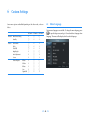
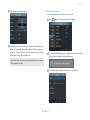
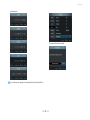
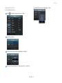
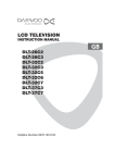
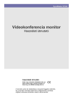
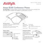
1
SyncMaster VC240
Video Conference System
User Guide
Information in this user guide is subject to change without prior notice for performance improvement.
◀ i
▶
Copyright
The color and design may differ depending on the model, and specifications
are subject to change without prior notice for performance improvement.
© 2010–2011 Samsung Electronics Co., Ltd.
All rights reserved by Samsung Electronics Co., Ltd. You are prohibited from
unauthorized use or reproduction of any of the information in this user guide
without prior approval from Samsung Electronics Co., Ltd.
• SyncMaster and the Samsung logo are registered trademarks of Samsung Electronics Co., Ltd.
• Microsoft, Windows, and Windows NT are registered trademarks of
Microsoft Corporation.
• VESA, DPM, and DDC are registered trademarks of Video Electronics
Standard Association.
All other brand names mentioned herein are trademarks of their respective
owners.
◀ ii
▶
CONTENTS
Contents
1
15
15
3 Network and Call Settings
3.1 Network Settings . . . . . . . . . . . . . . . . . . . . . . . . . .
17
17
Data Transmission Mode . . . . . . . . . . . . . . . . . . . . . .
H.323 Data Transmission . . . . . . . . . . . . . . . . . . . . . .
19
19
SIP Data Transmission . . . . . . . . . . . . . . . . . . . . . . .
NAT Traversal . . . . . . . . . . . . . . . . . . . . . . . . . . . .
Call Settings . . . . . . . . . . . . . . . . . . . . . . . . . . . . .
19
20
21
3
Call Quality . . . . . . . . . . . . . . . . . . . . . . . . . . . . .
Time . . . . . . . . . . . . . . . . . . . . . . . . . . . . . . . . .
21
23
Setup
4
Camera . . . . . . . . . . . . . . . . . . . . . . . . . . . . . . . .
25
2.1
Precautions . . . . . . . . . . . . . . . . . . . . . . . . . . . . . .
Power Supply . . . . . . . . . . . . . . . . . . . . . . . . . . . .
Installation . . . . . . . . . . . . . . . . . . . . . . . . . . . . . .
4
4
4
Cleaning . . . . . . . . . . . . . . . . . . . . . . . . . . . . . . .
Using the Product . . . . . . . . . . . . . . . . . . . . . . . . . .
5
5
Assembling the Product . . . . . . . . . . . . . . . . . . . . . .
Theft Prevention . . . . . . . . . . . . . . . . . . . . . . . . . . .
Mounting the Monitor to a Wall . . . . . . . . . . . . . . . . . .
7
8
9
2.3
Blocking Electromagnetic Waves . . . . . . . . . . . . . . . . .
Connections . . . . . . . . . . . . . . . . . . . . . . . . . . . . .
9
10
2.4
Connecting to a PC . . . . . . . . . . . . . . . . . . . . . . . . .
Connections for Video Calls . . . . . . . . . . . . . . . . . . . .
Finding the Best Viewing Angle . . . . . . . . . . . . . . . . . .
10
11
11
Powering On the Monitor . . . . . . . . . . . . . . . . . . . . .
Video Modes . . . . . . . . . . . . . . . . . . . . . . . . . . . . .
12
12
2.6
2.7
Video Signal Modes . . . . . . . . . . . . . . . . . . . . . . . . .
Navigating between Menus . . . . . . . . . . . . . . . . . . . .
Keyboard Modes . . . . . . . . . . . . . . . . . . . . . . . . . .
12
13
14
2.8
Power-saving Modes . . . . . . . . . . . . . . . . . . . . . . . .
15
Introduction
1.1 Features . . . . . . . . . . . . . . . . . . . . . . . . . . . . . . .
1.2 Package Contents . . . . . . . . . . . . . . . . . . . . . . . . . .
1
1
1
Accessories . . . . . . . . . . . . . . . . . . . . . . . . . . . . . .
Basic View . . . . . . . . . . . . . . . . . . . . . . . . . . . . . .
1
2
Remote Control . . . . . . . . . . . . . . . . . . . . . . . . . . .
1.3
2
Max. Power Saving Mode . . . . . . . . . . . . . . . . . . . . .
Standby Mode . . . . . . . . . . . . . . . . . . . . . . . . . . . .
2.2
2.5
◀ iii
3.2
3.3
4 Video Call
27
4.1
4.2
4.3
Making a Call . . . . . . . . . . . . . . . . . . . . . . . . . . . .
Answering a Call . . . . . . . . . . . . . . . . . . . . . . . . . .
Screen Layout . . . . . . . . . . . . . . . . . . . . . . . . . . . .
27
28
29
4.4
Making a Phone Book . . . . . . . . . . . . . . . . . . . . . . .
Adding a Group . . . . . . . . . . . . . . . . . . . . . . . . . . .
31
31
Renaming a Group . . . . . . . . . . . . . . . . . . . . . . . . .
Deleting a Group . . . . . . . . . . . . . . . . . . . . . . . . . .
Adding a Contact . . . . . . . . . . . . . . . . . . . . . . . . . .
31
32
32
Editing a Contact . . . . . . . . . . . . . . . . . . . . . . . . . .
Deleting a Contact . . . . . . . . . . . . . . . . . . . . . . . . .
33
33
Making a Call . . . . . . . . . . . . . . . . . . . . . . . . . . . .
Searching a Contact . . . . . . . . . . . . . . . . . . . . . . . . .
Recent-Call Log . . . . . . . . . . . . . . . . . . . . . . . . . . .
35
35
36
Viewing Call Details from the Call Log . . . . . . . . . . . . . .
Deleting a Call from the Call Log . . . . . . . . . . . . . . . . .
36
37
Making a Call . . . . . . . . . . . . . . . . . . . . . . . . . . . .
Adding a Contact to the Phone Book . . . . . . . . . . . . . . .
38
39
4.5
▶
CONTENTS
4.6
4.7
Zooming a Remote Caller’s camera . . . . . . . . . . . . . . . .
Remote Presentation . . . . . . . . . . . . . . . . . . . . . . . .
39
40
5
Video Conferencing with RADVISION SCOPIA Systems
41
6
Custom Settings
6.1 Menu Language . . . . . . . . . . . . . . . . . . . . . . . . . . .
6.2 Picture . . . . . . . . . . . . . . . . . . . . . . . . . . . . . . . .
44
44
45
PC or DVI Mode . . . . . . . . . . . . . . . . . . . . . . . . . . .
VC Mode . . . . . . . . . . . . . . . . . . . . . . . . . . . . . . .
45
49
Security . . . . . . . . . . . . . . . . . . . . . . . . . . . . . . . .
Reset Settings . . . . . . . . . . . . . . . . . . . . . . . . . . . .
Software Update . . . . . . . . . . . . . . . . . . . . . . . . . .
52
53
53
6.3
6.4
6.5
7
Troubleshooting Guide
Index
55
56
◀
iv ▶
1 Introduction
1.1 Features
1.2 Package Contents
The video conference system VC240 can be used for various purposes:
Accessories
• Use VC240 as an ordinary monitor.
• Make video calls over the Internet or a local network to VC240 or other
types of video conference systems.
• Conduct a multiparty video conference over an MCU (Multipoint Conferencing Unit).
Installation guide
Warranty card
User guide
Brochures
Power cord
VGA cable
LAN cable
DVI cable
Audio cable
Remote control
Batteries (AAA ☓ 2)
Ferrite core
Refer to Table 1 for specifications.
Table 1: Specifications
Screen size
59 cm (23.6 inches)
Aspect ratio (width ☓ length)
521.28 ☓ 293.22 mm
Pixel size
0.2715 mm
Horizontal frequency
30–81 kHz
Vertical frequency
56–75 Hz
Max. resolution
1920 ☓ 1080 @ 60 Hz
Dimensions (width ☓ height ☓ thickness)
568.6 ☓ 397.4 ☓ 77.7 mm (without the stand)
568.6 ☓ 440.0 ☓ 226.0 mm (with the stand)
Weight
8.8 kg (with the stand)
Cleaning cloth
◀ 1 ▶
1.2 Package Contents
Basic View
/
•
/
is used to open or close a menu, return to the last menu, or
delete the last character you typed.
1. Camera
2. Microphone
3. Remote control sensor
4. Speaker
•
VG is used to navigate between menus, or make a call.
•
VG is used to navigate between menus, or disable the microphone.
•
is used to navigate between menus, or lower the volume.
•
is used navigate between menus, or raise the volume.
.
.
.
.
•
•
This camera cannot be connected directly to a computer and thus cannot
be used for purposes other than video calls.
◀ 2 ▶
is used to change the video mode, or select a menu option.
powers on or off the monitor. See §2.8.
1.3 Remote Control
1.3 Remote Control
1.
.
2.
.
You can control the monitor by using the buttons on the remote control or on
the bottom of the monitor. Be sure the remote control is not lost.
3.
.
4.
.
powers on or off the monitor. See §2.8.
changes the video mode. See §2.5.
splits the screen to display the pictures from the camera and from
the PC at the same time. See §4.3.
and
zoom the camera in or out during a video call. See §4.6.
5.
,
,
, and
are used to navigate between menus, or change
the settings of each menu option. See §2.6.
6.
is used to control the camera during a video call. See §4.6.
7.
is used to send the picture from your PC to your remote party.
.
.
.
See §4.7.
8.
.
9.
.
shows the current video mode.
is used to make a video call. See Chapter 4.
. These buttons are used to type letters or numbers.
10
.
11.
.
.
12
.
.
13
.
.
14
.
switches between keyboard modes in order of numbers > capital
letters > lowercase letters. See §2.7.
disables the microphone.
displays a menu, or select an option.
and
decrease or increase the volume.
.
15
mutes the sound.
.
16
opens the Setup menu.
.
.
.
17
.
.
18
.
is used to return to the last menu, or delete the last character you
typed.
is used to exit a menu, or close a video call.
.
19
is used to display your telephone directory. See §4.4.
.
20
is not available for this product.
.
.
◀ 3 ▶
2 Setup
2.1 Precautions
• Neither bend nor pull the power cord, nor weigh it down with a heavy
Be sure to install the monitor in a place that satisfies the conditions indicated
in Table 2.
object. Otherwise, the power cord may be damaged and cause an electric shock or fire.
• Remove the dust around the plug pins and power socket with a dry
cloth. Dust may cause a fire.
Table 2: Environmental conditions
Operating temperature
Operating humidity
Storage temperature
Storage humidity
• Do not unplug the power cord when the product is in use. Otherwise,
an electric shock may damage the product.
10–40 °C (50–104 °F)
20–80%
• Be sure to hold the plug when unplugging the power cord. Otherwise,
−20–45 °C (−4–113 °F)
5–95%
an electric shock or fire may result.
• Do not use an unauthorized power cord. The power cord should have
been supplied by Samsung. Otherwise, an electric shock or fire may
result.
Power Supply
• Do not use a damaged power cord or a loose power socket. Otherwise,
an electric shock or fire may result.
• Place the power plug in an easily accessible area so that you can unplug
the power cord in order to completely cut the power to the product
when there is a problem. The power button alone on the product does
not completely cut the power.
• Do not plug or unplug the power cord with wet hands. Otherwise, an
electric shock may result.
• Be sure to plug the power cord into a grounded power socket. Otherwise, an electric shock or personal injury may result.
• Do not let the product or power plug contact heat appliances. Otherwise, an electric shock or fire may result.
• Do not plug many products into the same power socket. Otherwise, the
socket may overheat and cause a fire.
Installation
• Do not expose the product to a heat source, i.e. do not put a candle,
mosquito coil, or a lit cigarette on top of the product and do not install
the product near a heat appliance. Otherwise, a fire may result.
• Avoid installing the product in a narrow space with bad ventilation,
such as a bookshelf or wall closet. Otherwise, the inside temperature
may increase and cause a fire.
• Be sure to insert the power plug firmly into the socket. An unstable
connection may cause a fire.
• Keep the plastic bag for the product in a place that cannot be reached
by children. Children may suffocate.
◀ 4 ▶
2.1 Precautions
• Do not install the product in a vehicle or a place exposed to dust, moisture, oil, or smoke. Otherwise, an electric shock or fire may result.
Cleaning
• Be sure the power cord is removed when you clean the product. Oth-
• Do not install the product in a place that can be reached by children.
erwise, an electric shock or fire may result.
Children may knock the product down and injure themselves. The front
part of the product is heavy. Be sure to install it on a flat, stable surface.
• Do not spray the detergent directly onto the product. Otherwise, the
• Be sure to leave a space (10 cm or more) behind the product for ventilation when it is installed on a wall. Otherwise, a fire may result from
• Do not spray water directly onto the product. Neither let water enter
the product nor get the product wet. Otherwise, a fire, electric shock,
exterior or display is highly likely to discolor, crack, or peel off.
an increase in internal temperature.
or product defect may result.
• Do not install the product on an unstable structure or where there is
much vibration. Otherwise, the product may fall and break, and such
• Be sure to remove the power cord and wipe the product with a soft,
dry cloth. Do not use chemicals such as wax, benzene, alcohol, thin-
vibration may cause the product to fail or start a fire.
• Do not expose the product to direct sunlight, heat, or a hot object such
as a stove. Otherwise, the product life may be reduced, or a fire may
result.
• Take care not to drop the product when moving it. Otherwise, product
ner, mosquito repellent sprays, aromatic sprays, lubricant, or detergent.
Otherwise, the exterior may be damaged or the labels may be removed.
• The exterior of the product can be easily scratched. Be sure to clean
it using a dedicated cloth. Dampen the cloth with a small amount of
water. Remove any foreign substance from the cloth to avoid scratching
the product.
failure or personal injury may result.
• When installing the product in a cabinet or on a shelf, be sure the bottom
front part of the product does not protrude. Otherwise, the product
may fall off and break or cause a personal injury. Be sure to use a cabinet
or shelf appropriate for the product size.
• Installing the product in an unusual place may seriously affect its performance. Avoid a place exposed to a lot of fine particles, chemical
substances, or extreme temperatures; or operating the product continuously for many hours in an airport or train station.
• Do not place the product with the display facing down on the floor.
Using the Product
• High voltage runs through the product. Do not attempt to disassemble,
repair, or modify the product on your own. Otherwise, an electric shock
or fire may result. Contact Samsung’s service center for repair.
• If the product generates a strange noise, a burning smell, or smoke, remove the power cord immediately, and contact Samsung’s service center. Otherwise, an electric shock or fire may result.
• If the product falls or the exterior is damaged, power off the product,
remove the power cord, and contact Samsung’s service center. Otherwise, an electric shock or fire may result.
Otherwise, the display may be damaged.
• Put down the product carefully. Otherwise, product failure or personal
injury may result.
• Do not move the product by pulling the power cord or signal cable.
◀ 5 ▶
Otherwise, the power cord may be damaged and cause an electric shock
or fire.
2.1 Precautions
• Do not lift or swing the product only by the power cord or signal cable.
Otherwise, the power cord may be damaged and cause product failure,
• Displaying the same picture for many hours may cause an afterimage
or stain. If you will not use the product for many hours, activate power-
a fire or an electric shock.
saving mode or the moving-picture screen saver.
• Before you move the product, be sure to turn off the power switch and
remove all the connected cables, including the power cord. Otherwise,
the power cord may be damaged and cause an electric shock or fire.
• Do not let your child hang on to or mount the product. Otherwise, the
product may fall, and your child may be injured or even killed.
• Configure the appropriate resolution and frequency for the product.
Otherwise, your eyesight may weaken.
• Continuously watching the display from a close distance may weaken
your eyesight.
• Rest your eyes for at least five minutes every hour. This will relieve
• Neither let the product fall nor apply force to it. Otherwise, an electric
shock or fire may result.
• If there is a gas leak, do not touch the product or power plug; instead,
your eye fatigue.
• Keep small-sized accessories in a place that cannot be reached by children.
ventilate the room immediately. Otherwise, a spark can cause an explosion or fire. During a thunderstorm or lightning, do not touch the
power cord. Otherwise, product failure or personal injury may result.
• If you will not use the product for a long time, remove the power cord
• Neither use nor keep combustible spray or an inflammable substance
• Do not move or hold the product upside down only by the stand. Otherwise, the product may fall and break or cause personal injury.
near the product. Otherwise, an explosion or fire may result.
from the power socket. Otherwise, a fire may result from accumulated
dust, overheating, an electric shock, or electric leakage.
• Be sure the vent is not blocked by a table cloth or curtain. Otherwise, a
fire may result from an increase in internal temperature.
• Do not put the product near a humidifier or the kitchen table. Other-
• Do not put a metallic object or an object that contains liquid (a flower
• The display panel becomes hot when the product is on for many hours.
vase, a flowerpot, a drink, toiletries, medicines, etc.) on top of the product. If water or any foreign substance enters the product, remove the
power cord, and contact Samsung’s service center. Otherwise, product
• Be careful when you adjust the product angle or stand height. Otherwise, you may pinch your hand or finger. Tilting the product exces-
failure, a fire, or an electric shock may result.
• Do not insert a metallic object (a chopstick, coin, hair pin, etc.) or inflammable object (paper, match, etc.) into the vent or ports of the product. If water or any foreign substance enters the product, be sure to
power off the product, remove the power cord, and contact Samsung’s
service center. Otherwise, product failure, a fire, or an electric shock
wise, an electric shock or fire may result.
sively may cause it to fall and result in personal injury.
• Do not put a heavy object on top of the product. Otherwise, product
failure or personal injury may result.
• Be sure your child does not put a battery from the remote control in his
mouth. If your child swallows a battery, consult a doctor immediately.
• Be sure you use specified batteries. Do not use a new and used battery
together. Otherwise, a fire, personal injury, or contamination may result
from an explosion or internal fluid leakage of the batteries.
may result.
◀ 6 ▶
2.2 Assembling the Product
• Do not set the volume really high when you use headphones. A really
high volume may cause your hearing to weaken.
• Be sure the batteries are oriented in the right direction. Otherwise, a
2.2 Assembling the Product
1.
.
Lay the product packaging or a
thick cushion on the floor, and place
the product on top with the display
fire, personal injury, or contamination may result from an explosion or
internal fluid leakage of the batteries.
facing down. Turn the stand to the
opposite side of the camera.
• Used-up batteries (including rechargeable batteries) should be separated from general waste so that they can be collected for recycling.
You can discard discharged batteries at your local recycling center or
a battery dealer.
2.
Lift the stand so that it can be connected to the base.
3.
Insert the stand into the base.
.
.
◀ 7 ▶
2.2 Assembling the Product
4.
.
Tightly fasten the screw on the bottom of the base to the stand.
Theft Prevention
A slot for connecting an anti-theft Kensington lock can be found at the bottom
right on the back of the monitor. To
install your monitor in a public place,
connect a lock to the monitor following
the steps below:
1. Insert the lock into the slot in the
monitor.
.
5.
.
Be sure you do not remove the fixing pin from the stand before you
connect the stand to the base. Otherwise, injury may result. After
connecting the stand to the base,
remove the fixing pin, and adjust
the height of the stand. To fix the
height, fasten the fixing pin.
◀ 8 ▶
2. Fasten the lock.
.
3. Connect and fix the lock cable to
.
a heavy object such as a desk.
2.2 Assembling the Product
Mounting the Monitor to a Wall
Blocking Electromagnetic Waves
To mount the monitor to a wall, buy and attach to the monitor a 100 ☓ 100 or
200 ☓ 100 mm wall-mount bracket that complies with the VESA standards:
1.
.
2.
.
Unfasten the screw, and lift and remove the stand.
Attach the wall-mount bracket, and
fasten the screws.
The ferrite core can be used to block electromagnetic waves. Thread the LAN
cable through the ferrite core and tie a knot with the core close to the LAN
port.
Samsung is not liable for any defect caused by using a wall-mount bracket
that does not comply with the VESA standards.
◀ 9 ▶
2.3 Connections
2.3 Connections
Connecting to a PC
The monitor has two video inputs for
connecting to a PC. One is for DVI,
and the other is for VGA. Using a digital signal, DVI offer clearer pictures
than VGA which uses an analog signal.
Thus, it is best to connect the monitor to
a PC via DVI rather than VGA.
Connect the DVI cable from the DVI IN
socket on the monitor to the DVI output on the PC. Alternatively, connect
the VGA cable to the RGB IN socket on
the monitor and RGB OUT on the PC.
The monitor can be connected to two PCs at the same time via the DVI
and VGA inputs. However, you cannot view the pictures from both the
PCs at the same time.
To use the monitor’s speakers, instead
of using external speakers, connect the
audio cable from the audio output on
the PC to the AUDIO IN socket on the
monitor.
◀ 10
▶
2.4 Finding the Best Viewing Angle
2.4 Finding the Best Viewing Angle
To make a video call, the monitor
should be connected to a network.
Connect the LAN cable from the LAN
port on the router to the LAN port on
You can rotate or tilt the monitor in various ways, as shown below:
S
Connections for Video Calls
NG
SU
AM
H D Video Confe
ren
ce
the monitor. If the router has no more
ports available for the monitor, connect
one port on the monitor to the router
and then the other port on the monitor
to the PC. Then the PC can communicate with the router via the monitor.
The monitor’s camera has a microphone at the bottom; however, a headset will produce clearer audio for a
video call. Connect the microphone
and earphones of your headset to the
MIC and
spectively.
jacks on the monitor re-
The monitor can be rotated to a vertical orientation. However, check if the
graphics card on the PC supports a vertical display beforehand.
◀ 11 ▶
2.5 Powering On the Monitor
2.5 Powering On the Monitor
displays the current video mode at the
top left corner of the screen.
Before you power on the monitor, insert the batteries into the remote control, observing the polarity, which is marked on the base of the battery
The current time and the monitor’s IP address are displayed in VC mode,
while the current time and video signal mode are displayed in the other
compartment.
modes. To change the video mode, press
If the monitor does not respond to the remote
control, the batteries have been discharged. Be
sure to replace the batteries using standard 1.5V
AAA, taking into account the precautions below:
• Do not use different types of batteries together.
• Do not use a new and used battery together.
• Do not attempt to recharge discharged non-rechargeable batteries.
• It is best to remove the batteries if you are not going to use the remote
for a long time.
• Do not dispose of batteries with general waste.
Plug the power cord into the power socket, turn on the power switch on the
monitor, and press
you want is displayed.
Video Signal Modes
When a PC is connected to the monitor, the PC’s operating system usually
recognizes the monitor and starts the appropriate monitor driver. You do
not need to install a monitor driver if the displayed picture is clear. A
monitor driver should be installed if the displayed picture is shaky or not
clear.
When the picture from the PC displays normally, configure the resolution.
Check to see if the monitor is compatible with the graphics card on the PC if
the picture from the PC is not displayed even though the monitor is correctly
connected to the PC and the correct graphics card is selected (referring to
Table 3 ). Refer to Windows Help for details about how to change the refresh
on the remote control. The monitor will power on.
Video Modes
rate and resolution.
The following booting message will appear
when the monitor powers on. Booting takes
tens of seconds before you can make a video
call.
The following three types of video modes are offered.
PC:
View the picture from a PC connected via the VGA input.
DVI: View the picture from a PC connected via the DVI input.
VC:
repeatedly until the picture
View your self-image from the camera.
◀ 12
▶
2.6 Navigating between Menus
2.6 Navigating between Menus
Table 3: Video signal mode
Resolution
Horizontal
Vertical
Clock
Horizontal/Vertical
frequency
frequency
frequency
polarities
(kHz)
(Hz)
(MHz)
(H/V)
IBM, 640 ☓ 350
31.469
70.086
25.175
+/-
IBM, 720 ☓ 400
31.469
70.087
28.322
-/+
MAC, 640 ☓ 480
35.000
66.667
30.240
-/-
MAC, 832 ☓ 624
49.726
74.551
57.284
-/-
MAC, 1152 ☓ 870
68.681
75.062
100.000
-/-
VESA, 640 ☓ 480
31.469
59.940
25.175
-/-
VESA, 640 ☓ 480
37.861
72.809
31.500
-/-
VESA, 640 ☓ 480
37.500
75.000
31.500
-/-
VESA, 800 ☓ 600
35.156
56.250
36.000
+/+
VESA, 800 ☓ 600
37.879
60.317
40.000
+/+
VESA, 800 ☓ 600
48.077
72.188
50.000
+/+
VESA, 800 ☓ 600
46.875
75.000
49.500
+/+
VESA, 1024 ☓ 768
48.363
60.004
65.000
-/-
VESA, 1024 ☓ 768
56.476
70.069
75.000
-/-
1.
opens the main menu screen.
VESA, 1024 ☓ 768
60.023
75.029
78.750
+/+
VESA, 1152 ☓ 864
67.500
75.000
108.000
+/+
2.
and
VESA, 1280 ☓ 800
49.702
59.810
83.500
-/+
3.
selects a main menu option and opens its submenu.
VESA, 1280 ☓ 800
62.795
74.934
106.500
-/+
VESA, 1280 ☓ 960
60.000
60.000
108.000
+/+
4.
and
move between submenu options.
VESA, 1280 ☓ 1024
63.981
60.020
108.000
+/+
5.
and
confirm the selected submenu option.
VESA, 1280 ☓ 1024
79.976
75.025
135.000
+/+
VESA, 1440 ☓ 900
55.935
59.887
106.500
-/+
6.
and
return to the parent menu.
VESA, 1440 ☓ 900
70.635
74.984
136.750
-/+
7.
exits the current menu.
VESA, 1600 ☓ 1200
75.000
60.000
162.000
+/+
VESA, 1680 ☓ 1050
8.
65.290
59.954
146.250
-/+
VESA, 1920 ☓ 1080
67.500
60.000
148.500
+/+
You can navigate between menus using the following buttons:
.
.
.
.
.
.
.
.
◀ 13
▶
navigate between options in the main menu.
opens the Setup menu directly without accessing the main menu.
2.7 Keyboard Modes
2.7 Keyboard Modes
. To type a space, switch to uppercase or lowercase mode, and press
13
.
You can type in uppercase letters, lowercase letters, numbers, and several
symbols using three types of keyboard modes. The current keyboard mode
is shown in the right side of the field: ABC indicates uppercase mode, abc
lowercase mode, and 123 number mode.
To change the keyboard mode, press
repeatedly until the keyboard
mode you want is displayed. To type in
John@Office, follow the steps below:
1. To type an uppercase J, press
to switch to uppercase mode, and
.
press
.
2. To type a lowercase o, press
to switch to lowercase mode, and
.
press
three times.
3. To type h, press
twice.
4. To type n, press
twice.
5. To type @, press
twice.
.
.
.
6. To type an uppercase O, press
to switch to uppercase mode, and
.
press
three times.
7. To type a lowercase f, press
to switch to lowercase mode, and
.
press
three times.
8. To type the next f, wait until the cursor advances or press
.
the cursor, and then press
three times.
9. To type i, press
three times
10. To type c, press
three times.
11. To type e, press
twice.
.
.
.
12. To delete the previous letter, press
.
to advance
.
◀ 14
▶
.
2.8 Power-saving Modes
3. Set Max. Power Saving to On.
2.8 Power-saving Modes
.
As shown in Table 4, there are three types of power supply modes. The monitor enters active mode after you have pressed
on.
and the monitor has turned
Table 4: Power specification
Input power
100–240 V
Active mode
Less than 85 W
Standby mode
Less than 35 W
Max. power-saving mode
Less than 3 W
After the PC has turned on, the monitor will automatically turn itself on
Max. Power Saving Mode
With this mode active, the monitor can save energy by automatically switching itself to maximum power-saving mode when it is in DVI or PC mode and
.
2. Press
.
powered off by the
button.
You cannot receive an incoming call in maximum power-saving mode; the
monitor will not automatically power on.
the PC is turned off and is no longer sending a video signal.
1. If the monitor is in VC mode, press
when it receives a video signal from the PC . However, the monitor will
not automatically power on, even if it receives a video signal, if it was
to switch to DVI or PC mode.
to open the Setup screen.
Refer to Windows Help for details about how to configure power saving settings for your PC.
Standby Mode
In VC mode, you can set the monitor to automatically switch to standby mode
after the remote control has been left idle for a specified time:
1. If the monitor is in PC or DVI mode, press
.
◀ 15
▶
to switch to VC mode.
2.8 Power-saving Modes
2. Press
.
to open the Setup screen.
3. Select an interval for activating Standby mode. Each interval is a mul.
tiple of 10 minutes from 10 to 60 minutes.
If Standby is set to 10 minutes, the monitor will automatically turn off
and switch to standby mode after the remote control has been left idle
for 10 minutes.
4. To turn on the monitor again, press any button other than
.
.
The monitor will automatically turn on when a call is received during
standby mode. However, the monitor will not automatically power on,
even if it receives a call, if it was powered off by the
button.
◀ 16
▶
3 Network and Call Settings
2. To assign a dynamic IP address, set IP Assignment to Dynamic.
3.1 Network Settings
.
Consult your network administrator, and configure the network settings for
the monitor. The IP address can be assigned in one of the following two ways.
Static IP address: The same IP address will always be assigned to the monitor whenever it is powered on.
Dynamic IP address: A different IP address will be assigned to the monitor
each time it is powered on.
1. Press
.
to open the Setup screen, and select Network.
3. To assign a static IP address, set IP Assignment to Static, and fill the IP
Address, Subnet Mask, Gateway, and DNS Server fields.
.
4. Select OK to save the new settings.
.
5. You are advised to check that the IP settings are valid; select Network
.
Test. While the test is performed, the valid items will be indicated by a
◀ 17
▶
3.1 Network Settings
whereas the invalid items will be indicated by a
1. Select Speed & Duplex.
.
.
6. Assign the monitor a name so that it can be identified by other devices
.
connected to the network.
2. Select the LAN port connected to the router.
.
3. Adjust several options alternately until the connection succeeds.
.
Select Display Name, and enter a name.
The data transmission rate and mode are determined while the monitor tries
to connect to a router. Usually, the monitor is automatically connected; however, the connection attempt will sometimes fail. When the connection fails,
configure the data transmission rate and mode manually as follows:
◀ 18
▶
3.2 Data Transmission Mode
3. Set Network Preference to H.323.
3.2 Data Transmission Mode
.
You can make or receive calls using one of the following data transmission
protocols:
• H.323
• Session Initiation Protocol
H.323 Data Transmission
To make calls using the H.323 telephone number mode (E.164), configure the
settings as follows:
1. Press
.
4. If an H.323 gatekeeper is available, select H.323 Settings.
to open the Setup screen, and select Network.
.
a) Set Gatekeeper to On.
b) Fill the gatekeeper IP in the Address field.
2. Select Phone Number and enter a number. Dial by user name (alias) is
available in H.323 through the gatekeeper.
.
c) If data transmission fails due to firewall restrictions, set H.460
Traversal to On, and fill the H.460 server IP address.
5. Select OK to save the new settings.
.
SIP Data Transmission
To make calls using the SIP user name mode, configure the settings as follows:
◀ 19
▶
3.2 Data Transmission Mode
1. Press
.
4. Select SIP Settings.
to open the Setup screen, and go to Network.
.
2. Select User Name and enter a name. In SIP you can use both name and
number in URI for dialing.
a) Set SIP Proxy Server to On.
.
b) Fill the Display Name, Server Address, and Password fields.
5. Select OK to save the new settings.
.
H.323 and SIP modes cannot be used at the same time. To change the
current H.323 mode to SIP, set Network Preference to SIP.
3. Set Network Preference to SIP.
.
NAT Traversal
You can make or receive a call while being connected to ADSL or Cable router
from home or office. The system will use Network Address Translation from
internal IP to External IP. The system will use external HTTP server to discover the external IP to be used.
The external IP could be changed without note by Internet Service
Provider.
1. Press
.
to open the Setup screen and go to Network.
2. Select and open NAT Traversal.
.
◀ 20
▶
3.3 Call Settings
3. Set NAT Traversal to Yes.
3.3 Call Settings
4. Use NAT Auto Discovery on for system to discover it’s external public
IP automatically.
Call Quality
5. Following OK, discovered external public IP will be displayed.
You can adjust the sharpness of your image that is shown to the remote caller.
.
.
.
6. Use NAT Auto Discovery off for manual enter public IP address.
1. Press
.
.
to open the Setup screen, and go to Call Control.
When NAT Traversal is set to Yes then Gatekeeper and H.460 Traversal
must be set to Off and vise versa.
7. On Network select H.323 Settings and set Gatekeeper and H.460
Traversal to Off.
.
8. On Network select Ports Conflagrations and verify the system
.
TCP/UDP configured ports are enabled in the router. Refer to system
ports documentation.
When using NAT Traversal you need to set router to port forwarding.
2. Select Call Quality. The following screen will appear.
.
indicates that the LAN cable is not connected. Correct the LAN cable
connection if this symbol appears at the top right corner of the screen.
indicates that an IP address conflict has occurred. Change the IP address if this symbol appears at the top right corner of the screen.
3. To increase the sharpness, select a high value from Max Bandwidth.
Use Max Bandwidth to configure the call resolution high definition or
.
standard definition and call frame rate. For 1024 kbps and above HD
◀ 21
▶
3.3 Call Settings
resolution, max frame rate will be used.
4. A higher sharpness will compromise simultaneity. For instance, a picture of you waving a hand will appear delayed for a remote caller. For
.
6. A bad network connection also causes freeze picture during a call. Set
.
PLC to On. Video will not freeze in case of severe loss on network.
PLC will be used in case SVC is not active or not supported by remote
simultaneity, set Video Mode to Motion.
system.
5. A bad network connection sometimes corrupts the picture, which appears as a mosaic, during a call. Set SVC to On. Clear and normal
.
picture will be restored. SVC will be take effect while remote system is
capable to support it; for example, RADVISION VC240 and Elite MCU.
◀ 22
▶
3.3 Call Settings
3. Select the Time Zone corresponding to your region.
Time
.
Set the clock precisely so your video calls will be logged accurately.
1. Press
.
to open the Setup screen, and select Clock.
4. If Daylight Saving Time is in effect in your region, set Daylight Savings
to On.
.
2. The time server will allow the clock to always have the precise time. To
use the time server, set Clock Mode to On.
.
5. If you do not want to use the time server, select Clock Set, and enter
.
the date and time manually. Increase or decrease the date or time using
the
◀ 23
▶
or
button respectively. Alternatively, manually enter a date
3.3 Call Settings
as 18:24.
or time using the number keys on the remote.
6. In Date Format, DD indicates the day, MM the month, and YYYY the
.
year. If Date Format is set to DD/MM/YYYY and a call was made on
July 18, 2010, the date will be displayed as 18/07/2010.
7. If Time Format is set to 12 Hours and a call was made at 6:24 p.m., the
time will be displayed as PM 06:24. If you do not want to display AM
or PM, set Time Format to 24 Hours. Then the time will be displayed
.
◀ 24
▶
3.3 Call Settings
Camera
it is best to select Auto for most occasions.
Your picture may appear too dark or bright, or different in color for your
remote caller, depending on your ambient light intensity. Change several
settings so the remote caller can see you clearly:
1. Press
.
to open the Setup screen, and go to Camera.
4. Set Brightness to Manual, and adjust the brightness. However, it is best
to select Auto for most occasions.
.
2. Select the correct frequency from Power Frequency. Otherwise, the picture may continually move upward.
.
3. Set White Balance to Manual, and adjust the white balance. However,
.
◀ 25
▶
3.3 Call Settings
5. Rotating your monitor to a vertical orientation will rotate the camera,
and thus your image will appear rotated on the remote caller’s screen.
.
To resolve this, the remote caller should also rotate his monitor to a
vertical orientation, and you and the remote caller should set Flip to
Horiz. + Verti.
White Balance is used to generally adjust the color intensity for making
the brightest area in the picture white.
◀ 26
▶
4 Video Call
4. Alternatively, you can select a phone number from the recent-call log.
The selected phone number will be copied to the input field.
4.1 Making a Call
.
You can make a call, following the steps below:
1. Press
.
.
5. Press
.
.
The screen will display the recent-call log on the left, the phone number
field in the middle, and your image on the right.
2. If you want to hide your image or make a call to someone without a
camera, set Call Type to Voice.
.
The message Connected to will appear when the remote caller answers
the call.
6. To mute your voice during a call, press
.
3. Move the cursor to the input field, and enter the IP address of the remote
caller.
to disable the microphone.
will appear at the top right corner of the screen. To enable the mi-
.
crophone, press
.
will appear at the
7. To disable the speaker during a call, press
top right corner of the screen. To enable the speaker, press
again.
.
Refer to §2.7 for details about how to type.
◀ 27
again.
▶
4.2 Answering a Call
8. To end the call, press
.
4.2 Answering a Call
.
An incoming call will be indicated by a
dialog box as shown. Select Accept to accept the call, or select Reject to refuse the
call.
Select Yes. The call will be disconnected.
9. To view the recent-call log, select Call History. Refer to §4.5 for details
Configure the call answering settings, following the steps below:
.
1. Press
about the recent-call log.
.
to open the Setup screen, and go to Call Control.
10. To open the phone book, select Phone Book. Refer to §4.4 for details.
.
2. If you want to automatically connect to an incoming call, set Auto Answer to On.
.
◀ 28
▶
4.3 Screen Layout
When On + Mic Mute is selected, an incoming call will automatically
be connected, but your voice will not be heard by the remote caller.
4.3 Screen Layout
The image of the remote party will appear when your call is accepted.
3. If you want to refuse all incoming calls, set Do not Disturb to On.
.
The
button can be used to change the screen layout of yours and the
remote caller’s as required. Each time you press
, the screen layout will
change as shown below: The blue figure represents the remote caller, and the
green figure represents you.
• In DVI or PC mode
– A call is connected
– A call is not connected
4. An incoming call will be indicated by a ringtone. If you want to mute
the ringtone, select Audio, and set Sounds to Off.
.
• In VC mode
– A call is connected
– A call is not connected
You can change the size and location of the
smaller picture in this screen layout.
1. Press
.
◀ 29
▶
to open the Setup screen, and go to Input.
4.3 Screen Layout
2. Select a size from PIP Size. Two sizes are available.
ping image; go to PIP Transparency and select High, Medium, or Low.
.
3. Select a location from PIP Position. Five locations are available: bottom
right, top right, top center, top left, and bottom left.
.
4. The area on the screen concealed by the smaller picture will not be
shown. To expose a concealed area, adjust the opacity of the overlap.
◀ 30
▶
4.4 Making a Phone Book
2. Enter the name of a group, and select OK to save the name.
4.4 Making a Phone Book
.
You can make calls easily by using the phone book. To open the phone book,
press
.
Renaming a Group
1. Select a group, and press
.
.
Adding a Group
It is best to create a group before adding a phone number so you can search
and manage numbers easily.
1. Go to Group and select Add Group. The number in parentheses next
to each group name indicates the number of contacts.
.
2. Select Rename.
.
Enter a new group name, and select OK to save the change.
◀ 31
▶
4.4 Making a Phone Book
Deleting a Group
1. Select a group and press
.
Adding a Contact
1. Go to All and select Add Contact.
.
.
2. Select Delete. The selected group will be deleted, and its contacts will
be moved to the Unassigned group.
.
2. Enter a contact name in the Name field, and fill at least one of the IP,
URI, and Phone Number fields.
.
3. Specify Group, and select OK to save the new contact information.
.
◀ 32
▶
4.4 Making a Phone Book
3. Select Edit and change the information.
Editing a Contact
1. Select a contact and press
.
.
.
Select OK to save the changes and exit.
2. To view details of the contact before editing, select View.
Deleting a Contact
.
1. Select a contact and press
.
◀ 33
▶
.
4.4 Making a Phone Book
2. Select Delete.
.
press
Select OK. The contact will be deleted.
. The selected contacts will be indicated by a
5. After selecting all the contacts you want to delete, press
.
3. To delete all contacts, select Delete All.
last selected contact highlighted, and select Delete.
.
Select OK. All the contacts will be deleted.
Select OK. The selected contacts will be deleted.
4. To delete more than one contact at the same time, select the contacts and
.
◀ 34
▶
.
with the
4.4 Making a Phone Book
Making a Call
Searching a Contact
Select a contact and press
You can search a contact using the contact name or IP address.
.
1. Press
.
Alternatively, press
to open the phone book.
and select Call.
2. Move the cursor to the input field.
.
3. Enter capital or lowercase letters to search for contacts with names containing the same letters.
.
4. Enter numbers to search for contacts with IP addresses containing the
same numbers.
.
◀ 35
▶
4.5 Recent-Call Log
4.5 Recent-Call Log
To view the recent-call log, press
Alternatively, press
Viewing Call Details from the Call Log
1. Select a call from the call log, and press
.
and select Call History.
.
and select Call History.
2. Select View. Details showing when the call was made and how long it
lasted will appear.
.
• To view the incoming-call log, select Received.
• To view the outgoing-call log, select Sent.
• To view the missed-call log, select Missed.
◀ 36
▶
4.5 Recent-Call Log
3. To delete all the calls from the call log, select Delete All.
Deleting a Call from the Call Log
1. Select a call from the call log, and press
.
.
.
Select OK. All the calls in the call log will be deleted.
4. To delete more than one call from the call log at the same time, select
.
2. Select Delete.
.
the calls and press
Select OK. The call will be deleted.
. The selected calls will be indicated by a
5. After selecting all the calls you want to delete, press
.
◀ 37
▶
.
with the last
4.5 Recent-Call Log
Making a Call
selected call highlighted, and select Delete.
Select a call from the call log, and press
Select OK. The selected calls will be deleted from the call log.
Alternatively, press
◀ 38
▶
and select Call.
.
4.6 Zooming a Remote Caller’s camera
4.6 Zooming a Remote Caller’s camera
Adding a Contact to the Phone Book
You can add a contact from the call log to the phone book.
1. Select a call from the call log and press
.
You can zoom in or out the remote caller’s camera if it has the zooming function.
.
1. Select the remote caller’s camera using the
button.
2. To zoom in the remote caller’s camera, press
.
.
.
3. To zoom out the remote caller’s camera, press
.
.
The camera on VA240 does not offer the zooming function.
2. Select Save.
.
Select OK to save the new contact and exit.
◀ 39
▶
4.7 Remote Presentation
4.7 Remote Presentation
The remote presentation function is available only during an H.323 call.
Only one caller can give a remote presentation at a time.
It is not possible to do a remote presentation with resolution of 1600 ☓
1200.
You can send the picture from your computer to the remote caller and give a
remote presentation during a call:
to open the Setup screen, and go to Call Control. Set Pre1. Press
sentation Source to DVI if the monitor is connected to the PC via DVI.
.
Otherwise, select PC.
. The picture from your computer will replace the remote
2. Press
party’s image on his screen.
.
3. To stop the remote presentation, press
.
again.
◀ 40
▶
5 Video Conferencing with RADVISION SCOPIA Systems
You can use VC240 by itself for a high-definition video call between two
people (point-to-point video call). Enjoy additional features such as centralized management, multi-party conferencing, recording and streaming, and
firewall traversal by adding a video conferencing system with RADVISION
SCOPIA.
Multi-party call
Point-to-point call
Multipoint conferencing is accomplished by a Multipoint Conferencing Unit
(MCU), a device that manages a multipoint conference by connecting multiple sites into the same video conference. RADVISION’s SCOPIA Elite MCU
offers 1080-p, high-definition processing and personal layouts for each particRADVISION SCOPIA is a family of products delivered as network appliances and software, optimized to work with your VC240. Using RADVISION
SCOPIA, you can quickly deploy a scalable visual-communication network
and centrally manage the video network, enable multi-party meetings, and
extend a video conference to any laptop across any firewall.
ipant. You, along with other participants, control SCOPIA Elite conferences
with the VC240 remote control; you can mute participants, change the video
layouts, and invite other users to the conference.
High-end Desktop Video Conferencing
Multi-party (Multipoint) Conferencing
Video communication with the VC240 can be more effective and efficient with
Multipoint (Multi-Party) Conferencing. This is where more than one participant connects simultaneously. With multipoint conferencing, VC240 allows
users to see and hear several other participants as they are all in the same
location-in a virtual conference room.
Managers and executives want ways to easily extend video conferences to
large numbers of remote and desktop users and make communication more
efficient, easier, and broader in reach. RADVISION’s SCOPIA Desktop al-
◀ 41
▶
lows users to take conferencing wherever they go. SCOPIA Desktop is designed to meet the demands of high-performance video conferencing with
work to ensure the bandwidth is used efficiently. Also, easily schedule and
manage meetings, delivering high-quality video communication.
a standard PC and Internet connection. The latest in video technology are
included, providing HD H.264 format for viewing both participants and
for data collaboration. The audio system provides echo cancellation, back-
Recording and Streaming a Conference
ground noise suppression, and is highly resistant to network errors common
on the Internet.
SCOPIA Desktop is a simple web-browser plug-in that is centrally managed
and deployed on a PC without complex licensing fees or installation issues.
Click on a link and include teleworkers in meetings, participate in video conferences from the road, collaborate with partners and suppliers, and seam-
Enable conference recording through RADVISION’s SCOPIA solution. The
recording feature captures audio, video, and data-preserving meetings in
high definition for playback. VCR-style controls provide access to any part
of the recordings. RADVISION’s SCOPIA additionally enables integrated
streaming for conference webcasting to both PC-and Mac-based participants.
This allows viewers to see the video streams of both the speaker and the pre-
lessly connect through firewalls.
sentation content. Simultaneous unicast and multicast support extend the
meeting to a virtually unlimited number of participants.
Managing a Video Network
Firewall Traversal and NAT Solution
VC240 system administrators and users can be significantly more effective by
using a central-management system to perform tasks such as remote software
Firewalls are barrier devices placed between two separate networks that filter out unwanted packets, in many cases unintentionally blocking video-
upgrades, system configurations, monitoring, and operation. As the number of VC240 systems grows in a deployment, a central management system
can make administrators significantly more efficient at managing distributed
conferencing traffic. Many firewalls also combine filtering functions with network address translation (NAT) capability; the firewalls are usually located
at the border of the network they protect. SCOPIA PathFinder Firewall and
VC240 systems from a single point.
NAT Solution enable secure connections between enterprise networks and
remote sites. SCOPIA PathFinder maintains the security and advantages of
firewalls and NAT over video networks and allows seamless integration with
existing video endpoints and systems.
Learn More
To learn more on how RADVISION SCOPIA can help you set up your VC240,
visit http://www.radvision.com/VC240 or contact your regional RADVISION office.
RADVISION’s iVIEW Suite is the perfect solution for this requirement. A
comprehensive management solution is provided for collaborative video
communication. With iVIEW, effectively manage and monitor a video net-
◀ 42
▶
USA/AMERICAS
EMEA
APAC
T. +1 201 689 6300
T. +44 20 3178 8685
T. +852 3472 4388
F. +1 201 689 6301
F. +44 20 3178 5717
F. +852 2801 4071
[email protected]
[email protected]
[email protected]
◀ 43
▶
6 Custom Settings
Some menu options are disabled depending on the video mode, as shown
6.1 Menu Language
below.
Various menu languages are available. To change the menu language, press
General
Picture
VC mode
PC mode
DVI mode
Max. Power Saving
☓
◯
◯
Standby
◯
☓
☓
Video Mode
◯
☓
☓
Color
◯
☓
☓
Tint (G/R)
◯
☓
☓
MagicBright
☓
◯
◯
Auto Adjustment
☓
◯
☓
Screen
☓
◯
☓
R-Gain
☓
◯
◯
G-Gain
☓
◯
◯
B-Gain
☓
◯
◯
Size
☓
◯
◯
Digital NR
◯
☓
☓
Picture Options
◀ 44
to open the Setup screen, and go to General and select a language from
Language. The menu will be displayed in the selected language.
▶
6.2 Picture
6.2 Picture
Contrast, Brightness and Sharpness.
PC or DVI Mode
Adjusting the Brightness
You can adjust the brightness, following the steps below.
1. Press
.
to open the Setup screen, and go to Picture.
Preset MagicBright options are permanently defined. Custom settings will be applied to Custom.
2. Select an option from MagicBright.
.
4. To reset all Custom settings, select Picture Reset.
.
3. If the option you want is not available, select Custom, and then adjust
.
◀ 45
▶
6.2 Picture
Adjusting the Color Tone
Then select Reset Picture Mode.
You can change the color tone:
1. Press
.
to open the Setup screen, and go to Picture.
2. Select Picture Options.
.
◀ 46
▶
6.2 Picture
3. Select an option from Color Tone.
Picture Size and Location
.
You can change the picture size and location in PC mode:
1. Press
.
4. If the option you want is not available, select Custom, and then adjust
R-Gain, G-Gain, and B-Gain, which indicate red, blue, and green respectively. To change the color tone of the picture to yellow, change
to open the Setup screen, and go to Picture.
.
R-Gain and G-Gain to 100 and B-Gain to 0.
2. To automatically adjust the picture size and location in accordance with
the received video signal, select Auto Adjustment.
.
Preset Color Tone options are permanently defined. Custom settings
will be applied to Custom.
3. To manually adjust the picture size and location, select Screen.
.
◀ 47
▶
6.2 Picture
4. Decrease or increase Coarse to narrow or widen the picture respectively. To finely adjust the picture width, select Fine.
.
5. If the picture is not centered on the screen, select PC Position and then
Aspect Ratio
You can change the aspect ratio in PC or DVI mode:
.
1. Press
.
adjust the picture location using the
,
,
, or
button.
to open the Setup screen, and go to Picture.
2. Select Picture Options.
.
6. To reset the picture size and location, select Image Reset.
.
3. Select 16:9 or 4:3 from Size. It is best to select 4:3 for documents or 16:9
.
◀ 48
▶
6.2 Picture
VC Mode
for movies.
Adjusting the Brightness and Color Intensity
You can change the brightness and color intensity:
1. Press
.
to open the Setup screen, and go to Picture.
2. Select an option from Mode.
.
3. Adjust Contrast, Brightness, Sharpness, Color, and Tint (G/R) for the
.
◀ 49
▶
6.2 Picture
selected option.
Then select Reset Picture Mode.
4. To reset the custom settings for the current Mode, select Picture Reset.
.
◀ 50
▶
6.2 Picture
Adjusting the Color Tone
set Digital NR to Off, Low, Medium, High, or Auto.
You can change the color tone:
1. Press
.
to open the Setup screen, and go to Picture.
2. Select Picture Options.
.
3. Set Color Tone to Cool1, Cool2, Normal, Warm1, or Warm2.
.
4. Noise can occur in the picture of a very dynamic video. To avoid noise,
.
◀ 51
▶
6.3 Security
4. Because the initial password of most devices with a security function is
set to 0000, it is best to change the password. Enter a new password in
6.3 Security
.
You can set the monitor to be accessed only via a password.
1. Press
.
the Change PIN field.
to open the Setup screen.
5. If you forget your password, perform Reset Settings. The password
.
will be reset to 0000. Refer to the following section for details about
Reset Settings.
2. Select Security. Selecting Security will always display the following
password prompt. Enter the current password. The initial password is
0000. This is working only from 1004.17.
.
3. Set Functions Lock to On.
.
◀ 52
▶
6.4 Reset Settings
6.4 Reset Settings
6.5 Software Update
You can return the monitor to its default settings:
You can update the monitor software over the network. This will allow you
to use additional functions. System supports two ways of software upgrade:
1. Press
.
to open the Setup screen.
By pushing the software to the SCOPIA VC240 from iVIEW NMS server or an
external Windows (XP, 7)-based PC using the upgrade utility. Downloading
the software to the system GUI from an external local HTTP server. Please
refer to upgrade document available from customer support for HTTP server
setup.
1. Press
.
to open the Setup screen.
2. Select Reset Settings.
.
2. To view the monitor software version, select SW Version.
.
The monitor will restart itself after resetting. Note that all user configurations and the call logs will also be deleted.
◀ 53
▶
6.5 Software Update
3. Select SW Upgrade to start an update.
.
A software update cannot be performed during a call.
4. Enter the IP address of the software-update server in the input field, and
.
press
. Contact our service center or Radvision for getting the up-
dated released SW version. Upgrade server should be installed locally.
A software will appear on the server after setup. Refer to Chapter 5 for
details about Radvision.
5. Select the software for the product and start upgrade process.
.
◀ 54
▶
7 Troubleshooting Guide
Service Center
Check the following when there is a problem with the product.
1. If the status indicator is dark even when the monitor is powered on,
ensure the power cord is tightly connected to the monitor and socket.
.
Contact our service center for more information. (Please check the model
name and serial number in advance.)
2. If the message Check signal cable is displayed, tightly connect the
video cable to the monitor and PC.
.
3. If you remove and reconnect the video cable when Max. Power Saving
.
is set to On, the monitor may power off before it is recognized by the
PC. Be sure to change the setting to Off before the monitor is powered
off.
4. If the picture is displayed in a single color, ensure the video cable is
tightly connected to the monitor and PC.
.
5. If the picture from a desktop PC does not display normally after the
graphics card has been replaced, check to see if the correct driver for
.
the graphics card is installed. Then change the graphics card setting to
the video signal mode (resolution) supported by the monitor, referring
to Table 3.
6. If the monitor does not power on even after you pressed the
.
button,
check that the power switch (POWER S/W) on the back of the monitor
is turned on.
◀ 55
NORTH AMERICA
CANADA
800-SAMSUNG (726-7864)
http://www.samsung.com
MEXICO
800-SAMSUNG (726-7864)
http://www.samsung.com
USA
800-SAMSUNG (726-7864)
http://www.samsung.com
EUROPE
FRANCE
01 48 63 00 00
http://www.samsung.com
GERMANY
01805-SAMSUNG (726-7864)
http://www.samsung.com
ITALIA
800-SAMSUNG (726-7864)
http://www.samsung.com
SPAIN
902-1-SAMSUNG (726-7864)
http://www.samsung.com
ASIA
CHINA
400-810-5858
http://www.samsung.com
HONG KONG
3698-4698
http://www.samsung.com
JAPAN
0120-327-527
http://www.samsung.com/jp
KOREA
1588-3366
http://www.samsungsvc.co.kr
TAIWAN
0800-329-999
http://www.samsung.com
▶
INDEX
Index
Call Type, 27
Flip, 26
Missed, 36
Camera, 25
Functions Lock, 52
MM, 24
Change PIN, 52
4:3, 48
12 Hours, 24
16:9, 48
18/07/2010, 24
18:24, 24
24 Hours, 24
123, 14
Check signal cable, 55
Clock, 23
Gatekeeper, 19, 21
Clock Mode, 23
Gateway, 17
N
Clock Set, 23
General, 44
Name, 32
Coarse, 48
G-Gain, 44, 47
NAT Auto Discovery, 21
Color, 44, 49
Group, 31, 32
NAT Traversal, 20, 21
Connected to, 27
Contrast, 45, 49
Cool1, 51
ABC, 14
Cool2, 51
abc, 14
Custom, 45, 47
Add Contact, 32
Add Group, 31
Address, 19
All, 32
Audio, 29
AUDIO IN, 10
Auto, 25, 51
Motion, 22
Network, 17, 19–21
Color Tone, 47, 51
A
Accept, 28
Mode, 49, 50
G
H
Network Preference, 19, 20
H.323, 19
Network Test, 17
H.323 Settings, 19, 21
Normal, 51
H.460 Traversal, 19, 21
D
Date Format, 24
Daylight Savings, 23
DD, 24
DD/MM/YYYY, 24
Delete, 32, 34, 37, 38
Delete All, 34, 37
High, 30, 51
O
Horiz. + Verti., 26
On + Mic Mute, 29
I
P
Image Reset, 48
Password, 20
Input, 29
PC Position, 48
IP, 32
Phone Book, 28
IP Address, 17
Phone Number, 19, 32
IP Assignment, 17
Picture, 44–49, 51
Picture Options, 44, 46, 48, 51
Digital NR, 44, 51
L
Display Name, 18, 20
Picture Reset, 45, 50
LAN, 11
DNS Server, 17
PIP Position, 30
Language, 44
Do not Disturb, 29
PIP Size, 30
B
Low, 30, 51
DVI IN, 10
PIP Transparency, 30
B-Gain, 44, 47
Brightness, 25, 45, 49
Dynamic, 17
Auto Adjustment, 44, 47
Auto Answer, 28
M
MagicBright, 44, 45
C
E
Manual, 25
Call, 35, 38
Edit, 33
Max Bandwidth, 21
Call Control, 21, 28, 40
Call History, 28, 36
Call Quality, 21
Max. Power Saving, 15, 44, 55
F
Medium, 30, 51
Fine, 48
MIC, 11
◀ 56
▶
PLC, 22
PM 06:24, 24
Ports Conflagrations, 21
Power Frequency, 25
POWER S/W, 55
Presentation Source, 40
INDEX
R
U
Received, 36
Unassigned, 32
Reject, 28
URI, 32
Rename, 31
User Name, 20
Reset Picture Mode, 46, 50
Reset Settings, 52, 53
V
R-Gain, 44, 47
VESA, 9
RGB IN, 10
Video Mode, 22, 44
View, 33, 36
S
Voice, 27
Save, 39
Screen, 44, 47
W
Security, 52
Warm1, 51
Sent, 36
Warm2, 51
Server Address, 20
White Balance, 25
Setup, 13
Sharpness, 45, 49
SIP, 20
Y
YYYY, 24
SIP Proxy Server, 20
SIP Settings, 20
Size, 44, 48
Sounds, 29
Speed & Duplex, 18
Standby, 16, 44
Static, 17
Subnet Mask, 17
SVC, 22
SW Upgrade, 54
SW Version, 53
T
Time Format, 24
Time Zone, 23
Tint (G/R), 44, 49
◀ 57
▶