1
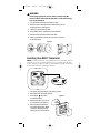
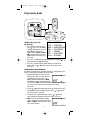
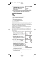
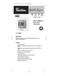
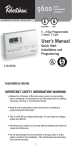
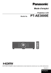
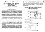
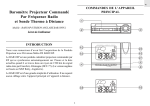
110-1165
6/8/05
11:51 AM
Page 1
8601
®
NeW
DIGITAL
PROGRAMMABLE
THERMOSTAT
G
E
O
H
GAS
ELECTRIC
OIL
HEAT PUMP
5 - 2 Day Programmable
1 Heat / 1 Cool
User’s Manual
110-1165
110-1098B
YEA
WO
2
WA
R
T
Quick Start
Installation and
Programming
RRANTY
As an ENERGY STAR® partner, Invensys Controls Americas has determined that
this thermostat meets the ENERGY STAR® guidelines for energy efficiency.
Application
The Robertshaw 8601 is a single-stage thermostat designed to control
24 VAC gas or electric heating and cooling systems or single-stage
heat pump. The 8601 requires a common wire.
Features
• Large backlit display.
• Four preprogrammed ENERGY STAR® setpoints for each day of
the week.
• Fahrenheit/Celsius display option.
• Programmable from 45°F (4°C) to 90°F (32°C).
• Accuracy within ± 1 degree.
• Adjustable temperature differential: 1-3 °F (1-1.5°C).
• Separate heating and cooling programs.
1
110-1165
6/8/05
11:51 AM
Page 2
! WARNING:
•
Always turn off power at the main power source by unscrewing
fuse or switching circuit breaker to the off position before installing,
removing, cleaning, or servicing thermostat.
•
Read all of the information in this manual before installing or
programming this thermostat.
•
DO NOT CONNECT TO 120 VAC. This is a 24V AC low voltage thermostat. Do not install on voltages higher than 30V AC.
•
All wiring must conform to local and national building and electrical
codes and ordinances.
•
Do not short (jumper) across terminals on the gas valve or at the
system control to test installation. This will damage the thermostat
and void the warranty.
•
Do not connect ground to any terminal in this unit.
Recycling Thermostat
If this thermostat REPLACES a thermostat that contains mercury,
DO NOT discard the old thermostat in the regular trash. Mercury
is harmful to humans and the environment. For this reason, do
not open, break, or crush the mercury cell. If mercury leaks from
a damaged cell, DO NOT touch or handle mercury with bare
hands. Use protective, non-absorbent gloves to place mercury
into a sealable container. Fill the container with sand or another
absorbent material and seal the container completely.
Return the mercury or mercury products, in a sealed container, to
Invensys Controls Americas or a local recycling center for proper
disposal. If you have any questions, call Robertshaw technical
support at 1-800-445-8299.
Invensys Controls Americas
28C Leigh Fisher Blvd.
El Paso, TX 79906
Attn: Mercury Recycling Center
Replacing Existing Thermostat
Wiring Table
Old Label
New Label
Description
M, W, Rh, Rc
R5, V or 5
R
24VAC, hot side
C, X or B
C
24VAC, common side
Y or Y6
Y1
Cooling control
H, W or 4
W1
Heating control
F or G
G
Fan control relay
O
O
Cool active reversing valve
B
B
Heat active reversing valve
NOTE: THIS THERMOSTAT REQUIRES A 24 VAC COMMON WIRE FOR PROPER OPERATION.
NOTE: ON SOME OLDER MODELS, THE C TERMINAL CAN BE EITHER THE COOLING CONTROL OR
THE COMMON SIDE OF THE TRANSFORMER. CHECK FURNACE WIRING DIAGRAM TO
VERIFY C TERMINAL. IF IT IS THE COMMON SIDE OF THE TRANSFORMER, CONNECT TO
THE C TERMINAL.
2
110-1165
6/8/05
11:51 AM
Page 3
! WARNING:
In heat pump applications, do not connect anything to the W1
terminal. When switched to HP mode, W1 is connected internally
to Y1 on the thermostat.
1. Turn off power to heating and cooling system.
2. Remove cover of old thermostat to expose wires. Do not
disconnect wires. (See Figure 1)
3. Label wires per the Wiring Table.
4. After labeling wires, remove wires from terminals.
5. Remove existing thermostat base from wall.
6. Refer to the following section for instructions on how to
install thermostat.
Figure 1
Installing Item 8601 Thermostat
NOTE: FOR
NEW INSTALLATIONS, MOUNT THERMOSTAT ON AN INSIDE WALL,
4-5 FEET
DO NOT INSTALL BEHIND A DOOR, IN A CORNER, NEAR AIR VENTS,
DIRECT SUNLIGHT, OR NEAR ANY HEAT OR STEAM GENERATING FIXTURES. INSTALLATION
THESE PLACES WILL AFFECT THERMOSTAT OPERATION.
ABOVE THE FLOOR.
IN
AT
heat off
a/c
auto
on
MON
°
F
prog temp vac
hold
select
heat off
set
a/c
auto
on
°
F
1. Turn power off to the heating and cooling systems.
2. Place HEAT-OFF-A/C in OFF position.
Figure 2
3. Place AUTO
ON switch
into AUTO position.
4. Remove the cover using a coin
or screwdriver (see Figure 2).
5. Place thermostat against the
wall at desired location. Make
sure wires will feed through
opening on base of thermostat.
on
auto
off
heat
cool
°
F
MON
t
c se
p va clock
t temld hold
ho
run/se
prog
select
3
set
110-1165
6/8/05
11:51 AM
Page 4
Figure 3
Mounting Holes
MON
°
F
C
R
G
O
B
Y1
W1
HP OPTION SWITCH
Heat pump switch.
ELECTRIC/GAS SWITCH
Selects fan control.
6. Mark placement of mounting holes (see Figure 3). Set base aside.
7. Drill the marked holes using a 3/16” (5mm) drill bit. NOTE: Enclosed
plastic anchors do not require a drilled hole for drywall.
8. Tap plastic anchors into the wall.
9. Align base with plastic anchors and feed wires through opening
(see Figure 3).
10. Secure base to wall with supplied screws.
11. Connect wires to terminal strip. Refer to wiring diagrams on page 5.
Make sure wire connections are secure.
12. Place Electric/Gas switch into either the ELEC or GAS position
depending on the type of furnace (see Figure 3).
13. Place the HP option switch into either the NON_HP or HP position
depending on the type of system you are using (see Figure 3). Use
the HP position for heat pumps ONLY. Use the NON_HP setting for
everything else.
14. Replace cover on thermostat by snapping into place.
15. Turn on power to system. Test thermostat as described in the
section To Test Thermostat.
4
110-1165
6/8/05
11:51 AM
Page 5
Wiring Diagrams
The following is just a sample of the most common types of HVAC
systems. Refer to your system’s installation manual for wiring information.
HEAT/COOL
4-WIRE
SINGLE TRANSFORMER
R
Transformer
Hot
C
24 VAC
120 VAC
Heating
Control
W1
Cooling
Control
Y1
Fan
Control
G
O
HEAT ONLY
3-WIRE
SINGLE TRANSFORMER
R
T
H
E
R
M
O
S
T
A
T
Transformer
C
Hot
24 VAC
120 VAC
Heating
Control
Y1
Fan
Control
B
COOL ONLY
3-WIRE
SINGLE TRANSFORMER
HEAT ONLY
2-WIRE
SINGLE TRANSFORMER
R
C
Hot
24 VAC
120 VAC
Heating
Control
W1
Y1
G
O
B
R
Transformer
T
H
E
R
M
O
S
T
A
T
R
C
Hot
120 VAC
24 VAC
W1
Compressor
Contactor
Y1
Fan
Relay
G
Reversing
Valve
O
C
Hot
24 VAC
120 VAC
W1
Cooling
Control
Fan
Control
Y1
G
O
B
T
H
E
R
M
O
S
T
A
T
HEAT PUMP WITH
HEAT ACTIVE
REVERSING VALVE
HEAT PUMP WITH
COOL ACTIVE
REVERSING VALVE
Transformer
G
O
B
Transformer
W1
T
H
E
R
M
O
S
T
A
T
R
T
H
E
R
M
O
S
T
A
T
Transformer
C
Hot
120 VAC
24 VAC
W1
Compressor
Contactor
Y1
Fan
Relay
G
O
Reversing
B
Valve
T
H
E
R
M
O
S
T
A
T
B
NOTE: Make sure the HP switch is in the HP
position. When switched to HP mode,
W1 is connected internally to Y1.
NOTE: Make sure the HP switch is in the HP
position. When switched to HP mode
W1 is connected internally to Y1.
5
110-1165
6/8/05
11:51 AM
Page 6
To Test Thermostat
! WARNING: DO NOT SHORT (JUMPER) ACROSS TERMINALS OF GAS
VALVE OR SYSTEM CONTROL TO TEST OPERATION. THIS WILL
DAMAGE THE THERMOSTAT AND VOID YOUR WARRANTY.
CAUTION: DO NOT SWITCH SYSTEM TO A/C OR LEAVE IN A/C MODE IF
THE TEMPERATURE IS BELOW 50°F (10°C). THIS CAN
DAMAGE THE AIR CONDITIONING SYSTEM AND CAUSE PERSONAL INJURY.
1. Place the HEAT-OFF-A/C switch into the A/C
position. The will be displayed.
2. Press the button until the temperature
setting is at least 3 degrees below the room
temperature. The air conditioning system
should turn on within a few seconds.
heat off
a/c
NOTE: ONCE THE THERMOSTAT TURNS OFF WHEN IN THE A/C MODE,
A BUILT IN 5-MINUTE DELAY PREVENTS THE SYSTEM FROM
TURNING ON AGAIN. THIS PROTECTS THE COMPRESSOR. NO
ADDITIONAL TIME DELAY RELAY IS REQUIRED. TO OVERRIDE THE
5-MINUTE DELAY FOR INSTALLATION, PRESS THE RESET BUTTON.
3. Put the HEAT-OFF-A/C switch into the OFF
position. The air conditioning system should
turn off.
heat off
a/c
4. Put the HEAT-OFF-A/C switch into the HEAT
position. The will be displayed.
5. Press the button until the temperature
heat off a/c
setting is at least 3 degrees above room
temperature. The heating system should turn on. The fan may
not turn on immediately, depending on the fan delay built into
the furnace.
NOTE: If HP is selected, the heat will not come on until the 5 minute
short cycle protection has expired.
6. Put the HEAT-OFF-A/C switch into the OFF
position. The heating system should turn off.
The fan may continue to run for a short
period of time.
7. Put the AUTO
ON switch into the ON
position. The blower fan should turn on.
The display will show a .
heat off
a/c
auto
on
auto
on
8. Put the AUTO
ON switch into the AUTO
position. The blower fan should turn off.
6
110-1165
6/8/05
11:51 AM
Page 7
Programming Guide
on
heat off
a/c
auto
on
MON
°
F
Cursor
prog temp vac
hold
set
select
prog temp vac
hold
set
select
SETTING TIME OF DAY AND
DAY OF WEEK
1. Press SELECT until the cursor is
over . Press SET. The HOURS
segment will be blinking. Use the
or button to adjust the
HOURS setting. NOTE: The AM or
PM indicator will change as the
HOURS display rolls through a 24
hour cycle.
MON
TUE
WED
THU
FRI
SAT
SUN
=
=
=
=
=
=
=
MONDAY
TUESDAY
WEDNESDAY
THURSDAY
FRIDAY
SATURDAY
SUNDAY
2. Press SET. The MINUTES segment will be blinking. Use the
button to adjust the MINUTES setting.
or
3. Press SET. The DAY segment will be blinking at the top of the
display. Use the or button to adjust the day of the week.
Press SET.
PROGRAMMING YOUR THERMOSTAT
The 8601 thermostat features 1-button programming. Simply follow these
steps to customize your thermostat for your lifestyle.
1. Place the HEAT-OFF-A/C switch into the
HEAT position. Make sure the cursor is in
the PROG position. Press SET. The
HOURS segment will be blinking. MON
thru FRI (the work week) will be displayed
across the top. AM1 will be illuminated in the lower right hand corner. You can now start programming the first event of the
work week.
2. Use the
or
button to adjust the hour of the first event. Press SET.
3. The MINUTES segment will be blinking. Use the
adjust the minutes. Press SET.
or
button to
4. The temperature should be blinking. Use the or button to
adjust the desired temperature of the first event. Press SET.
5. AM2 should now be displayed. Repeat
steps 2-4 to program the remaining events
(PM1 and PM2) for the work week. There
are a total of 4 events.
7
110-1165
6/8/05
11:51 AM
Page 8
6. After pressing SET for the 4th event, the
day of the week along the top will switch
to SAT SUN and AM1 will be displayed.
Repeat steps 2-4 to program the
weekend settings.
7. With the weekend settings programmed, place the HEAT-OFF-A/C
switch in the A/C position. Repeat steps 2-6 to program the
cooling settings.
CUSTOMIZING YOUR THERMOSTAT
Settings
System
A/C: The thermostat controls the cooling.
Off: The heating and cooling systems are off.
Heat: The thermostat controls the heat.
Fan
Auto: Equipment controls the fan.
On: The fan operates continuously.
Temperature Differential
The temperature differential is factory set at 1.0°F (.5°C). This means that
whenever the room temperature changes by one degree Fahrenheit
from the temperature setting, the system will turn on. If the system turns
on too often, increase the temperature differential.
Changing Fahrenheit (°F) to Celsius (°C), Clock Setting, Temperature
Differential, and Filter Monitor
You can change temperature scales (F or C), set a 12 or 24 hour clock,
adjust differentials and change the filter monitor setting by following
these instructions.
1. Press SELECT and SET at the same time.
Hold for 3 seconds. An F should be
blinking in the display. Use the or
button to toggle between Farhenheit (F)
or Celsius (C).
2. Press SET. CLOC will be displayed in the
lower left corner. Use the or
button to toggle between 12 or 24 for the
clock setting.
3. Press SET. diFF will be displayed in the
lower left corner. Use the or
button to adjust the 1st stage differential
between 1°F and 3°F (1°C and 1.5°C).
4. Press SET. CHECK FILTER will be
displayed and the length of the filter setting will be blinking in the lower left corner. Use the or button to adjust the
filter setting from 0 (OFF) to 9900 hours.
NOTE: The filter timer is based on
equipment run time. Select the length of time based on your filter's
recommended service interval.
5. Press SET or wait 5 seconds and the thermostat will return to the
normal operating mode.
8
110-1165
6/8/05
11:51 AM
Page 9
Begin Programmed Operation
1. Make sure the cursor is above PROG.
2. Place AUTO
ON switch into AUTO.
3. Place HEAT-OFF-A/C switch into A/C or HEAT depending on
the season.
heat off
a/c
auto
on
heat off
MON
°
a/c
auto
on
F
prog temp vac
hold
select
set
prog temp vac
hold
select
Temporary Program Hold
You can temporarily increase or decrease the temperature and hold it for
3 hours or until the next program event, whichever comes first.
1. Press the or button. The temperature will blink. Using the
or button, adjust the temperature to the desired level.
2. Press SET.
Another way to select a temporary hold is:
1. Press SELECT until the cursor is over TEMP HOLD. Press SET.
The temperature will be blinking. Use the or button to change
the temperature.
2. Press SET.
To cancel a temporary hold, press SELECT until the cursor is above PROG.
Press SET.
Vacation Hold
You can set your thermostat to hold a desired temperature for 1-365 days.
Vacation hold terminates at midnight of the last day. The thermostat
returns to normal operation the next day at 12:01 AM.
1. Press SELECT until the cursor is over VAC HOLD. Press SET. The
temperature will be blinking. Use the or button to change the
temperature.
2. Press SET. 365d will be displayed. Use the
between 1 and 365 days.
or
button to adjust
3. Press SET.
To cancel a vacation hold, press SELECT until the cursor is above PROG.
Press SET.
9
110-1165
6/8/05
11:51 AM
Page 10
Check Filter Reset
Once the filter timer has expired,
CHECK FILTER will turn on and stay
on. To clear the message and reset
the timer:
1. Press SELECT and SET and hold
for 3 seconds. CLr will appear in
the time display.
2. Press any key to clear the message.
The display will transition to the temperature scale display. See step 4 in
CUSTOMIZING YOUR THERMOSTAT.
3. No further input is needed. Within a few seconds, the display will
return to the normal operating mode.
Backlit Display
This thermostat is equipped with a backlight to make night time temperature adjustments quick and easy. Press the
button to activate the
backlight. The backlight will turn off after about 10 seconds of inactivity.
Reset
The RESET button is located above the upper left corner of the display.
Only use the reset feature if the thermostat is malfunctioning.
RESET
BUTTON
MON
°
F
C
R
G
O
B
Y1
W1
10
110-1165
6/8/05
11:51 AM
Page 11
Troubleshooting
Symptom
Thermostat does not turn
on system.
Remedy
Check wiring.
(See Installing Item 8601
Thermostat)
Thermostat turns on and off too
frequently.
Increase temperature differential.
(See Programming Guide)
System fan does not operate
properly.
Move the Electric/Gas switch to
either gas or electric, to match
system. (See Installing Item
8601 Thermostat)
Time shown on display is not the
current time of day.
Change time of day setting.
(See Programming Guide)
Thermostat does not
follow program.
Thermostat may not have been
programmed in HEAT or A/C
position. Verify program.
Check AM/PM indicators at time
of day and programmed time
changes.
(See Programming Guide)
Verify program and day of week
are correct.
(See Programming Guide)
If problems with thermostat cannot be resolved, call:
Technical Support: (800) 445-8299
Monday-Friday 7:30-5:30 CST
For after hours service, a 24-hour
automated help line is available.
11
110-1165
6/8/05
11:51 AM
Page 12
TWO-YEAR LIMITED WARRANTY
Invensys Controls Americas warrants to the original contractor
installer or to the original consumer user, each new Robertshaw thermostat to be free from defects in materials and workmanship under normal
use and service for a period of two (2) years from date of purchase. This
warranty and our liability does not apply to batteries or merchandise that
has been damaged by misuse, neglect, mishandling, alterations, improper
installation, or use in a way other than in accordance with Invensys
Controls Americas recommendations and instructions.
Invensys Controls Americas agrees to repair or replace at its option any
thermostat under warranty provided it is returned within the warranty
period, postage prepaid, with proof of the date of purchase. Cost of
thermostat removal or reinstallation is not the responsibility of Invensys
Controls Americas.
Repair or replacement as provided under this warranty is the exclusive
remedy of the consumer. Invensys Controls Americas shall not be liable
for any incidental or consequential damages for breach of any express or
implied warranty on this product, or under any other theory of liability.
Except to the extent prohibited by applicable law, any implied warranty of
merchantability or fitness for a particular purpose on this product is limited to the duration of this warranty.
Some states do not allow the exclusion or limitation of incidental or consequential damages, or allow limitations on how long an implied warranty
lasts, so the above limitations or exclusions may not apply to you. This
warranty gives you specific legal rights, and you may also have other
rights which vary from state to state.
For warranty returns, send thermostat, shipping prepaid to:
Invensys Controls Americas
Warranty Department
515 South Promenade Avenue
Corona, CA 92879-1736
Controls Americas
191 E. North Avenue
Carol Stream, Illinois 60188
United States of America
©2005 Invensys Controls Americas
110-1165
12