1
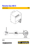
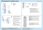
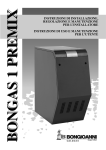
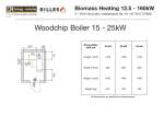
REMEHA GAS 360/460
High-efficiency atmospheric
gas boilers with reduced
NOx emission
GAS 360/460
ATMOSPHERIC
Outputs:
Gas 360 54 - 117 kW
Gas 460 119 - 380 kW
Gas
360/460
Atmospheric Range
TreadLightly
ON THE PLANET
Introduction
Boiler description
The Remeha Atmospheric
Range of boilers are high
efficiency atmospheric
gas boilers.
The Remeha Atmospheric Range is a series of floor standing, cast
iron, sectional boilers with a powder coated enamel steel casing
complete with glass fibre insulation. The Gas 360/460 both come
with high/low atmospheric gas burners, suitable for natural gas
and LPG.
The burner bed consists of
stainless steel atmospheric
burners which guarantee low
noise operating levels.
The boilers are pre-wired with site wiring connections and are
fitted to the instrument panel in the front casing.
All boilers are supplied with electronic ignition control via the pilot
burner for hot water central heating and are supplied with safety
equipment with ionisation flame detection.
The Remeha Atmospheric Range are designed to be connected to
most flue systems. All boilers have built in draught diverters.
The Gas 360 and Gas 460 boilers are delivered with a high/low
control panel.
Certifications
The Gas 360 and 460 boilers are in compliance with the
EC directives:
-
90/396/EEC Gas Appliance Directive
-
EN 297; EN656 Ref Standard
-
73/23/EEC Low Voltage Directive
Reference Standard: EN 60.335.1
-
89/336/EEC Electromagnetic Compatibility Directive
Reference Standard: EN 50.081.1 ; EN 50.082.1 ; EN 55.014
-
92/42/EEC Efficiency Directive **
The Gas 360 is CE approved, No: 0085AU0115
The Gas 460 is CE approved, No: 0085BL0187
Contents
2
page
Introduction
2
Boiler description
2
Certifications
2
Technical data Gas 360/Gas 460
3
Typical boiler construction Gas 360
4
Typical boiler construction Gas 460
5
Dimensions Gas 360
6
Dimensions Gas 460
7
Typical boiler installation Gas 360
8
Typical boiler installation Gas 460
9
Instrument panels
10
External connections
10
Water treatment
11
Remeha Gas 360
Number of sections
Nominal heat output
Nominal heat input
Mass flue gas flow rate (1) (2)
E.F.G.T Flue gas temperature Tf (1) (2)
Minimum flow temperature
Maximum flow temperature
Maximum operating pressure
Electrical supply
Power consumption (3)
Gas connection
Flow & return connection
Internal diameter flue gas outlet
Water resistance (1)
kW
kW
Kg/h
°C
°C
°C
bar
V/Hz
W
BSP
BSP
mm
mbar
mbar
mbar
litre
kg
Δ T = 10°C
Δ T = 15°C
Δ T = 20°C
Water capacity
Dry weight
At nominal output (2nd stage)
Boiler temperature 80°C
(3)
Power consumption of the boiler only with no accessories
(1)
(2)
8
10
36-63
39.4-68.9
138
45-81
49.1-88.4
177
12
54-117
58.8-127.2
255
14
180
56
25
14
32.6
257
200
120
53
30
39.8
305
220
320
142
80
54.2
408
54-99
58.8-107.8
216
135
30
90
6
230/50
25
1"
1 1/2"
200
216
96
54
47
357
REMEHA GAS 360/460
Technical data
Conditions of use - Maximum safety temperature: 110°C
- Maximum operating pressure: 6 bar
- Thermostat adjustable from 30 to 90°C
- Safety thermostat: 110°C
Remeha Gas 460
Number of sections
8
10
12
14
16
18
20
Nominal heat output
kW 83-140 107-180 131-220 155-260 179-300 202-340 226-380
kW 93.1-153 119.4-196.3 145.6-239.4 171.9-282.6 197.9-325.4 224-368.4 250.1-411.3
Nominal heat input
Mass flue gas flow rate (1)
Kg per sec 0.097
0.127
0.144
0.177
0.191
0.203
0.258
E.F.G.T Flue gas temperature Tf (2)
°C
125
123
130
126
133
140
126
Minimum flow outlet temperature
°C
40
Maximum flow outlet temperature
°C
90
Maximum operating pressure
bar
6
Electrical supply
V/Hz
230/50
Power consumption
W
108/114 maximum
Gas connection
BSP
1"
1"
1"
1 1/4"
1 1/4"
1 1/4"
1 1/2"
Flow & return connection
inch
2
Internal diameter flue gas outlet
mm
250
300
300
350
350
350
400
Δ T = 10°C mbar
80
133
198
277
369
484
592
Δ T = 15°C mbar
36
59
88
123
164
211
263
Water resistance (1)
Δ T = 20°C mbar
20
33
50
69
92
118
148
Water capacity
litre
61
76
91
106
122
137
154
Dry weight
kg
668
807
934
1096
1227
1354
1476
(1)
(2)
At 2nd stage
Boiler temperature 80°C
1 mbar = 10 mmCE = 10 daPa = 100 Pa
3
Typical boiler construction
Remeha Gas 360
Upper insulation
Smoke nozzle
Electrical connections area
DIEMATIC-m Delta
or K control panel
Draught diverter
with inspection trap
and motorised flap
Heating
flow
Closing
flap motor
Eutectic
cast iron
boiler
body
Gas inlet
Red painted
steel casing
Heating return
with drain
Floor plate
1st stage gas valve
Pressure outlet
Boiler body and
draught diverter +
combustion chamber
system insulation, in
glass wool, 100 mm
thick + glass fabric
2nd stage gas valve
Draught diverter
thermostat
-provided on DTG 220-7
and 8 Eco.NOx
-optional on other
models
Auto-ignition
Wet combustion chamber
irrigated on three sides
2 stage atmospheric burner with full
premixing (pull-out drawer)
4
4
Insulation above
draught diverter
Electrical connections area
DIEMATIC-m Delta
or K control panel
Flue nozzle
Red painted
steel casing
Draught diverter
with inspection trap
REMEHA GAS 360/460
Remeha Gas 460
Heating
flow
Eutectic
cast iron
heating
body
Heating return
with drain
Gas inlet
(reversible)
2-stage valve-controller
assembly with minimum
pressure switch
Back insulation
Ionization sensor
Boiler body insulation,
combustion chamber
and draught diverter
made of 100 mm thick
glass wool + glass
fabric
Ignition burner
Ignition electrode
Burner drawer
guide system
on rollers
Ignition transformer
EcoNOx burner
2-stage with total premixing
Removable burner
drawer
5
Dimensions
Remeha Gas 360
1 Connecting the safety
valves 1" BSP
2 Heating outlet 1 1/2" BSP
3 Heating return 1 1/2" BSP
4 Drain off 3/4" BSP
5 Gas inlet 1" BSP
Remeha Gas 360 - Dimensions
Number of sections
A (mm)
B (mm)
C (mm)
E (mm)
F (mm)
Ø G internal (mm)
6
8
10
12
14
946
952
102
75
494
180
1113
1007
124
75
578
200
1280
1007
124
75
661
200
1447
1007
124
75
745
225
REMEHA GAS 360/460
Remeha Gas 460
1 Heating outlet 2" BSP
2 Heating return 2" BSP
3 Drain off 3/4" BSP
Remeha Gas 460 - Dimensions
Number of sections
A (mm)
B (mm)
C (mm)
D (mm)
E (mm)
Ø F (mm) (20 mbar)
Ø G internal (mm)
H (mm)
J (mm)
8
10
12
14
16
18
20
970
1362
165
632
445
BSP1"
250
447
1094
1146
1362
165
808
445
BSP1"
300
535
1094
1322
1362
165
984
445
BSP1"
300
623
1094
1498
1412
190
1160
454
BSP 1 1/4"
350
704
1194
1674
1412
190
1336
454
BSP 1 1/4"
350
792
1194
1850
1412
190
1512
454
BSP 1 1/4"
350
880
1194
2026
1462
220
1688
507
BSP 11/2"
400
963
1194
7
Typical boiler installation
Remeha Gas 360
1 boiler in boiler room
Front View
Side View
2 boilers in boiler room
Rear View
Remeha Gas 360 - Dimensions
Sections
A (mm)
B (mm)
8
8
10
12
14
946
952
1113
1007
1280
1007
1447
1007
V = min. length 0.5 m before elbow, thus avoiding downdraught
W = min. 150 mm with vertical flue outlet
W = min. 0.5D + 50 mm with horizontal flue outlet
REMEHA GAS 360/460
Remeha Gas 460
1 boiler in boiler room
Front View
Side View
2 boilers in boiler room
Front View
Remeha Gas 460 - Dimensions
Sections
A (mm)
B (mm)
8
10
12
14
16
18
20
970 1146 1322 1498 1674 1850 2026
1362 1362 1362 1412 1412 1412 1462
V = min. length 0.5 m before elbow,
thus avoiding downdraught
W = min. 150 mm with vertical flue outlet
W = min. 1\2 Flue Diameter + 50 mm with
horizontal flue outlet
* = free access to rear of boiler
9
Instrument panels
Equipment contents
The panels contain all the necessary control and measuring instruments required to control the
boiler. The connections have to be made on a terminal strip. The capillaries and sensor wires,
which come from the control panel, are placed in the instrument pockets that are fitted at the
front of the boiler.
3-position switch: - auto
- manual
- safety thermostat test
110°C safety thermostat
with manual reset
Slot for the flue
gas thermometer
(available as option)
Boiler thermometer
On/Off switch
Double burner/heating pump switch
External connections
10
A4 circuit breaker
Number of burner stages
selection switch
1st and 2nd-stage lights
Burner alarm light
with reset button
1st and 2nd-stage
thermostats adjustable
from 40 to 90°C
Slot for hour
run meters
The system should be filled with mains cold
water (pH of between 7 and 8 in the UK).
Pressurised installations with a boiler/
system content ratio of 1:10 or less should
not require water treatment, provided that
the following conditions apply:
1. The system is flushed thoroughly to
remove all fluxes and debris and then
filled completely once.
2. Make up water is limited to 5% per
annum.
3. The hardness of the water does not
exceed 360 ppm (20°D).
All scale deposits will reduce the efficiency
of the boiler and should be prevented.
However provided the above is complied
with any scale produced will not be too
detrimental to the boiler efficiency and will
not reduce the anticipated life expectancy
of the boiler.
Note: Scale deposits in excess of 3 to
5 mm will reduce boiler efficiency and
greatly increase the risk of premature
casting failure.
As most systems contain a variety of metals
which can react with each other to cause
corrosion, it is considered good practice to
provide some form of water treatment
(especially in open vented systems) in order
to prevent or reduce the following:
- Metallic corrosion;
- Formation of scale and sludge;
- Microbiological contamination;
- Chemical changes in the untreated
system water.
Suitable chemicals and their use should be
discussed with a specialist water treatment
company prior to carrying out any work.
The specification of the system and
manufacturer’s recommendations must be
taken into account, along with the age and
condition of the system. New systems
should be flushed thoroughly to remove all
traces of flux, debris, grease and metal
swarf generated during installation. Care to
be taken with old systems to ensure any
black metallic iron oxide sludge and other
corrosive residues are removed, again by
thoroughly flushing, ensuring that the
system is drained completely from all
low points.
Note: Please ensure that the new boiler
plant is not in circuit when the flushing
takes place, especially if cleansing
chemicals are used to assist the process.
UNDER NO CIRCUMSTANCES
OPERATE THE BOILER WITH CLEANING
CHEMICALS IN THE SYSTEM.
REMEHA GAS 360/460
Water treatment
To Summarise:
- Minimise water loss;
- Prevent pumping over in open vented
systems;
- Provide adequate air venting at all high
points;
- Keep pH level between 7 - 9 when using
additives;
- Maximum chlorine content of 200 mg/l
- Take advice on the suitability of inhibitors.
Noise level
The noise level measured around the boiler
depending on boiler room construction is
about 50-55 dBA. (Noise level taken at 1
metre from the boiler).
Chimneys
The average flue gas temperature is so low
that the chimney must be in accordance
with the guidelines of British Gas and
BS 6644.
11
TreadLightly
GAS 360/460
ATMOSPHERIC
Broag Ltd. Head Office
Remeha House
Molly Millars Lane
Wokingham
Berkshire RG41 2QP
T: 0118 978 3434
F: 0118 978 6977
E: [email protected]
www.uk.remeha.com
The data published in this technical sales leaflet is based on the latest information (at date of publication)
and may be subject to revisions. It should be read in conjunction with our full technical brochure (available
on request). We reserve the right to continuous development in both design and manufacture, therefore
any changes to the technology employed may not be retrospective, nor may we be obliged to adjust
earlier supplies accordingly.
Issue 5 date: 01/02/08
Broag UK is committed to carbon offsetting
Designed and produced by Sans Frontiere Marketing Communications – 01273 487 800 – www.sansfrontiere.co.uk
ON THE PLANET