1
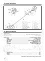
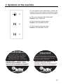
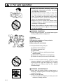
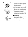
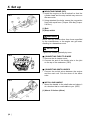
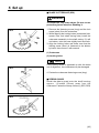
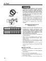
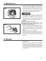
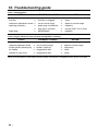
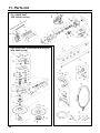
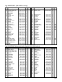
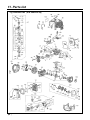
T3066-93110(103)
OWNER / OPERATOR MANUAL
RECIPROCATOR
SGCZ2500S
WARNING
WARNING
The engine exhaust from this product
contains chemicals known to the State
of California to cause cancer, birth
defects or other reproductive harm.
Before using our products, please
read this manual carefully to
understand the proper use of your
unit.
APPLICABLE SERIAL NUMBERS :
DRIVE UNIT 000101 and up
ENGINE UNIT 2842 and up
SAFETY FIRST
Instructions contained in warnings within this
manual marked with a
symbol concern
critical points which must be taken into
consideration to prevent possible serious
bodily injury, and for this reason you are
requested to read all such instructions
carefully and follow them without fail.
■ WARNINGS IN THE MANUAL
WARNING
This mark indicates instructions which must be
followed in order to prevent accidents which could
lead to serious bodily injury or death.
IMPORTANT
This mark indicates instructions which must be
followed, or it leads to mechanical failure,
breakdown, or damage.
NOTE
This mark indicates hints or directions useful in the
use of the product.
1.
2.
3.
4.
5.
6.
7.
8.
9.
10.
11.
CONTENTS
Parts location …………………………………4
Specifications …………………………………4
Symbols on the machine ……………………5
For safe operation ……………………………6
Set up …………………………………………12
Fuel……………………………………………14
Operation ……………………………………16
Maintenance …………………………………19
Storage ………………………………………23
Troubleshooting guide ………………………24
Parts list ………………………………………25
1. Parts location
1.
2.
3.
4.
5.
6.
7.
8.
Loop handle
Shoulder strap hanger
Ignition switch
Throttle cable
Throttle lever
Throttle set button
Drive shaft housing
Debris guard
9.
10.
11.
12.
13.
14.
15.
16.
Blade
Cuttercase
Spark arrester
Starter knob
Fuel tank
Primer pump
Choke lever
Air cleaner cover
2. Specifications
■ SGCZ2500S
Overall size(LxWxH)·························································· 76.0(1930)x9.8(250)x9.8(250) in(mm)
Dry weight w/o acc.······························································································· 14.8 lbs (6.7kg)
Engine Type······················································································ Air-cooled 2-stroke gasoline
Model········································································································ Zenoah GZ25N
Displacement ······················································································· 1.6cu-in (25.4cm3)
Max. output ··································································· 1.2Hp (0.9kW)at 7500/min-1(rpm)
Idle speed··························································································3000±200/min-1(rpm)
Fuel ······················································································· Mixture(Gasoline 50 : Oil 1)
Carburetor ··················································································· Walbro Diaphragm type
Spark plug·····································································································NGK CMR7A
Durability period ·····································································································300 hrs
Standard operation speed·········································································8000~9500 rpm
Fuel tank capacity·······························································································22.0 fl.oz (0.65 )
Transmission ································· Centrifugal clutch, Gear reduction Rigid driveshaft & Crank mechanism
Reduction ratio ······················································································································· 7.87
Standard Accessories
Shoulder Strap ·········································································································· 1 pc.
Goggle ······················································································································· 1 pc.
Tool Kit ······················································································································ 1 pc.
Specifications are subject to change without notice.
❲4 ❳
3. Symbols on the machine
For safe operation and maintenance, symbols are
carved in relief on the machine. According to these
indications, please be careful not to take a mistake.
(a) The port to refuel the "MIX GASOLINE"
Position: FUEL TANK CAP
(b) The direction to close the choke
Position: AIR CLEANER COVER
(c) The direction to open the choke
Position: AIR CLEANER COVER
IMPORTANT
ENGINE INFORMATION
THIS ENGINE MEETS U.S. EPA PH2
AND 2001 CALIFORNIA EMISSION
REGULATIONS FOR SI SORE’s
COMPLIANCE PERIOD : CATEGORYA:
ENGINE FAMILY : 1KZXS.0254QR ; EM
ENGINE DISPLACEMENT : 25.4cc
REFER TO OWNER’S MANUAL FOR MAINTENANCE SPECIFICATIONS AND ADJUSTMENTS.
INFORMATION IMPORTANTE
CONCERNANT LE MOTEUR
Ce moteur est conformc aux normcs U.S.
EPA PH2 et 2001 ainsi qu’aux autres dispositions
ultérieures de la réglementation concernant la pollution
de l’air pour les petits moteurs tout-terrain avec une
période de accordable : CATEGORYA.
Type de moteur : 1KZXS.0254QR :EM
Cylindrée du moteur : 25,4cc
Se référer au Manuel de l’utilisateur pour les
spécifications d’entretien et les réglages.
❲5 ❳
4. For safe operation
1. Read this manual carefully until you
completely understand and follow all safety
and operating instructions.
2. Keep this manual handy so that you may refer
to it later whenever any questions arise. Also
note, if you have any questions which cannot
be answered herein, contact the dealer from
whom you purchased the product.
3. Always be sure to include this manual when
selling, lending, or otherwise transferring the
ownership of this product.
4. Never allow children or anyone unable to fully
understand the directions given in the manual
to use the machine.
■ WORKING CONDITION
1. When using the product, you should wear proper
clothing and protective equipment.
(1) Helmet
(2) Ear protectors
(3) Protection goggles or face protector
(4) Thick work gloves
(5) Non-slip-sole work boots
2. And you should carry with you.
(1) Attached tools and files
(2) Properly reserved fuel
(3) Spare blade
(4) Things to notify your working area (rope,
warning signs)
(5) Whistle (for collaboration or emergency)
(6) Hatchet or saw (for removal of obstacles)
3. Do not wear loose clothing, jewelry, short
trousers, sandals, or go barefoot. Do not wear
anything which might be caught by a moving
part of the unit. Secure hair so it is above
shoulder length.
■ WORKING CIRCUMSTANCE
1. Never start the engine inside a closed room or
building. Exhaust gases contain dangerous
carbon monoxide.
2. Never use the product,
a. when the ground is slippery or when you can’t
maintain a steady posture.
❲6 ❳
4. For safe operation
b. At night, at times of heavy fog, or at any other
times when your field of vision might be
limited and it would be difficult to gain a clear
view of the working area.
c. During rain storms, during lightning storms, at
times of strong or gale-force winds, or at any
other times when weather conditions might
make it unsafe to use the product.
■ WORKING PLAN
1. You should never use the product when under
the influence of alcohol, when suffering from
exhaustion or lack of sleep, when suffering from
drowsiness as a result of having taken cold
medicine or at any other time when a possibility
exists that your judgment might be impaired or
that you might not be able to operate the product
properly and in a safe manner.
2. When planning your work schedule, allow plenty
of time to rest. Limit the amount of time over
which the product is to be used continuously to
somewhere around 30~40 minutes per session,
and take 10~20 minutes of rest between work
sessions. Also try to keep the total amount of
work performed in a single day under 2 hours or
less.
WARNING
1. If you don’t observe the working time, or
working manner (See ■ USING THE
PRODUCT), Repetitive Stress Injury(RSI)
could occur.
If you feel discomfort, redness and swelling
of your fingers or any other part of your
body, see a doctor before getting worse.
2. To avoid noise complaints, in general,
operate product between 8a.m. and 5p.m. on
weekdays and 9a.m. to 5p.m. weekends.
NOTE
Check and follow the local regulations as to sound
level and hours of operations for the product.
❲7 ❳
4. For safe operation
■ BEFORE STARTING THE ENGINE
1. The area within a perimeter of 50 feet (15m) of
the person using the product should be
considered a hazardous area into which no one
should enter. If necessary yellow warning rope,
warning signs should be placed around the
perimeter of the area. When work is to be
performed simultaneously by two or more
persons, care should also be taken to constantly
look around or otherwise check for the presence
and locations of other people working so as to
maintain a distance between each person
sufficient to ensure safety.
2. Check the condition of working area to avoid any
accident by hitting hidden obstacles such as
stumps, stones, cans, or broken grass.
IMPORTANT
Remove any obstacle before beginning work.
3. Inspect the entire unit for loose fasteners and
fuel leakage. Make sure that the cutting
attachment is properly installed and securely
fastened.
4. Be sure the debris guard is firmly attached in
place.
5. Always use the shoulder strap. Adjust the strap
for comfort before starting the engine. The strap
should be adjusted so the left hand can
comfortably hold the handlebar grip
approximately waist high.
■ STARTING THE ENGINE
1. The product is equipped with a centrifugal clutch
mechanism, so the cutting attachment begins to
rotate as soon as the engine is started by putting
the throttle into the start position. When starting
the engine, place the product onto the ground in
a flat clear area and hold it firmly in place so as
to ensure that neither the cutting part nor the
throttle come into contact with any obstacle
when the engine starts.
❲8 ❳
4. For safe operation
WARNING
Never place the throttle into the high speed
position when starting the engine.
2. After starting the engine, check to make sure
that the cutting attachment stops rotating when
the throttle is moved fully back to its original
position. If it continues to rotate even after the
throttle has been moved fully back, turn off the
engine and take the unit to your authorized Red
Max servicing dealer for repair.
■ USING THE PRODUCT
IMPORTANT
Cut only materials recommended by the
manufacturer. And use only for tasks explained
in the manual.
1. Grip the handles firmly with both hands using
your whole hand. Place your feet slightly apart
(slightly further apart than the width of your
shoulders) so that your weight is distributed
evenly across both legs, and always be sure to
maintain a steady, even posture while working.
2. Keep cutting attachment below waist level.
3. Maintain the speed of the engine at the level
required to perform cutting work, and never raise
the speed of the engine above the level
necessary.
4. If the unit start to shake or vibrate, turn off the
engine and check the whole unit. Do not use it
until the trouble has been properly corrected.
5. Keep all parts of your body away from rotating
cutting attachment and hot surfaces.
6. Never touch the muffler, spark plug, or other
metallic parts of the engine while the engine is in
operation or immediately after shutting down the
engine. Doing so could result in serious burns or
electrical shock.
❲9 ❳
4. For safe operation
• IF SOMEONE COMES
1. Guard against hazardous situations at all times.
Warn adults to keep pets and children away
from the area. Be careful if you are approached.
Injury may result from flying debris.
2. If someone calls out or otherwise interrupts you
while working, always be sure to turn off the
engine before turning around.
■ MAINTENANCE
1. In order to maintain your product in proper
working order, perform the maintenance and
checking operations described in the manual at
regular intervals.
2. Always be sure to turn off the engine before
performing any maintenance or checking
procedures.
WARNING
The metallic parts reach high temperatures
immediately after stopping the engine.
3. When replacing the cutting attachment or any
other part, or when replacing the oil or any
lubricant, always be sure to use only RedMax
products or products which have been
certified by RedMax for use with the RedMax
product.
4. In the event that any part must be replaced or
any maintenance or repair work not described in
this manual must be performed, please contact a
representative from the store nearest RedMax
authorized servicing dealer for assistance.
5. Do not use any accessory or attachment other
than those bearing the RedMax mark and
recommended for the unit.
6. Under no circumstances should you ever take
apart the product or alter it in any way. Doing so
might result in the product becoming damaged
during operation or the product becoming unable
to operate properly.
■ HANDLING FUEL
1. The engine of the RedMax product is designed
to run on a mixed fuel which contains highly
flammable gasoline. Never store cans of fuel or
❲ 10 ❳
4. For safe operation
refill the tank of the unit in any place where there
is a boiler, stove, wood fire, electrical sparks,
welding sparks, or any other source of heat or
fire which might ignite the fuel.
2. Never smoke while operating the unit or refilling
its fuel tank.
3. When refilling the tank, always turn off the
engine and allow it to cool down. Take a careful
look around to make sure that there are no
sparks or open flames anywhere nearby before
refueling.
4. Wipe spilled fuel completely using a dry rag if
any fuel spillage occurs during refueling.
5. After refueling, screw the fuel cap back tightly
onto the fuel tank and then carry the unit to a
spot 10 feet or more away from where it was
refueled before turning on the engine.
■ TRANSPORTATION
1. When hand-carrying the product, cover over the
cutting part if necessary, lift up the product and
carry it paying attention to the blade.
2. Never transport the product over rough roads
over long distances by vehicle without removing
all fuel from the fuel tank. If doing so, fuel might
leak from the tank during transport.
❲ 11 ❳
5. Set up
SE1
■ MOUNTING ENGINE (SE1)
1. Install the engine to the driveshaft so that the
cylinder head and the stop switch may come on
the same side.
2. Using attached four bolts, secure the connection
firmly with equal force (Torque: 25in-lbs)(Torque:
2.8 N.m.).
(1) Bolt
(2) Stop switch
WARNING
Never use any screws other than those specified
by the manufacturer, or the engine can get loose,
resulting in a hazardous event.
IMPORTANT
Tighten the screws gradually by turns.
SE2
■ CONNECTING THROTTLE WIRE
1. Remove the air cleaner cover.
2. Connect the end of the throttle wire to the joint
on the top of the carburetor. (SE2)
■ CONNECTING SWITCH WIRES
• Connect the switch wires between the engine
and the main unit. Pair the wires of the same
color.
SE3
■ INSTALLING HANDLE
• Mount the handle to the shaft tube and clamp it
at a location that is comfortable to you. (SE3)
(1) About 19 inches (48cm)
❲ 12 ❳
5. Set up
■ BLADE CUTTERCASE (SE4)
WARNING
The blade has very sharp edges. Be sure to use
protective gloves whenever handling it.
SE4
1. Remove the fastening screw (long) and the lock
screw (short) from the cuttercase.
2. While aligning the locking holes (cuttercase hole,
spacer hole, and shaft casing hole) install the
cuttercase assembly to the shaft casing. If it will
not bottom, twist the case slightly back and forth.
3. Align the locking holes and make sure that the
locking screw (short) is fastened to the bottom
by hand, then secure it with wrench.
(1) Cuttercase
(2) Locking holes
NOTE
SE5
If the locking screw is tightened up with the holes
out of alignment, the cuttercase may be damaged.
4. Fasten the cuttercase fastening screw (long).
■ DEBRIS GUARD
Install the debris guard onto the shaft housing
approx. 1.2inches (30mm) away from the
cuttercase. Fasten the clamp uniformly. (SE5, SE6)
SE6
❲ 13 ❳
6. Fuel
WARNING
• Gasoline is very flammable. Avoid smoking
or bringing any flame or sparks near fuel.
Make sure to stop the engine and allow it
cool before refueling the unit. Select outdoor
bare ground for fueling and move at least
3m(10ft) away from the fueling point before
starting the engine.
• The RedMax engines are lubricated by oil
specially formulated for air-cooled 2-cycle
gasoline engine use. If RedMax oil is not
available, use an anti-oxidant added quality oil
expressly labeled for air-cooled 2-cycle engine
use. (JASO FC GRADE OIL or ISO EGC
GRADE)
RECOMMENDED MIXING RATIO
GASOLINE 50:OIL 1
50:1 MIXING CHART
GASOLINE gal. 1
2
3
4
5
2-CYCLE OIL fl.oz 2.6 5.2 7.8 10.4 13
GASOLINE liter
2-CYCLE OIL ml
1
20
2
40
3
60
4
80
5
100
• Exhaust emission are controlled by the
fundamental engine parameters and
components(eq., carburation, ignition timing
and port timing) without addition of any
major hardware or the introduction of an
inert material during combustion.
• These engines are certified to operate on
unleaded gasoline.
• Make sure to use gasoline with a minimum
octane number of 90 ROZ(USA/Canada : pump
octane min.87)
• Unleaded gasoline is recommended to reduce
the contamination of the air for the sake of your
health and the environment.
• Poor quality gasolines or oils may damage
sealing rings, fuel lines or fuel tank of the
engine.
■ HOW TO MIX FUEL
1. Measure out the quantities of gasoline and oil to
be mixed.
2. Put some of the gasoline into a clean, approved
fuel container.
3. Pour in all of the oil and agitate well.
4. Pour in the rest of gasoline and agitate again for
at least one minute.
5. Put a clear indication on the outside of the
❲ 14 ❳
6. Fuel
container to avoid mixing up with gasoline or
other containers.
6. Indicate the contents on outside of container for
easy identification.
■ FUELING THE UNIT
1. Untwist and remove the fuel cap. Rest the cap
on a dustless place.
2. Put fuel into the fuel tank to 80% of the full
capacity.
3. Fasten the fuel cap securely and wipe up any
fuel spillage around the unit.
WARNING
1. Select bare ground for fueling.
2. Move at least 10 feet (3 meters) away from the
fueling point before starting the engine.
3. Stop the engine before refueling the unit.
FOR YOUR ENGINE LIFE, AVOID;
1. FUEL WITH NO OIL(RAW GASOLINE) – It will
cause severe damage to the internal engine
parts very quickly.
2. GASOHOL – It can cause deterioration of rubber
and/or plastic parts and disruption of engine
lubrication.
3. OIL FOR 4-CYCLE ENGINE USE or WATER
COOLED 2-CYCLE ENGINE USE – It can
cause spark plug fouling, exhaust port blocking,
or piston ring sticking.
4. Mixed fuels which have been left unused for
a period of one month or more may clog the
carburetor and result in the engine failing to
operate properly.
❲ 15 ❳
7. Operation
■ STARTING ENGINE
OP1
WARNING
The cutting head will start rotating upon the
engine starts.
OP2
(1)
(2)
(3)
1. Rest the unit on a flat, firm place. Keep the
cutting head off the ground and clear of
surrounding objects as it will start rotating upon
starting of the engine.
2. Push the primer pump several times until
overflown fuel flows out in the clear tube. (OP1)
3. Move the choke lever to the closed position.
(OP2)
4. Set the ignition switch to the “start” position.
(OP3)
5. While pulling the throttle lever, pull out the
starter rope quickly until engine fires. (OP4)
(1) choke lever (2) close (3) open
(4) ignition switch (5) start (6) stop
OP3
IMPORTANT
• Avoid pulling the rope to its end or returning it by
releasing the knob. Such actions can cause
starter failures.
OP4
6. Move the choke lever downward to open the
choke. And restart engine. (OP2)
7. Allow the engine to warm up for a several
minutes before starting operation.
NOTE
1. When restarting the engine immediately after
stopping it, leave the choke open.
2. Overchoking can make the engine hard to start
due to excess fuel. When the engine failed to
start after several attempts, open the choke and
repeat pulling the rope, or remove the spark plug
and dry it.
■ STOPPING ENGINE (OP3)
1. Release the throttle lever and run the engine for
a half minute.
2. Shift the ignition switch to the STOP position.
IMPORTANT
• Except for an emergency, avoid stopping the
❲ 16 ❳
7. Operation
engine while pulling the throttle lever.
OP5
.04 in
(1~2mm)
■ ADJUSTING THROTTLE CABLE
• The normal play is 1 or 2mm when measured at
the carburetor side end. Readjust with the cable
adjuster as required. (OP5)
(1) cable adjuster
(1)
OP6
■ ADJUSTING IDLING SPEED (OP6)
1. When the engine tends stop frequently at idling
mode, turn the adjusting screw clockwise.
2. When the cutting head keeps rotating after
releasing the trigger, turn the adjusting screw
counter-clockwise.
(1) idle adjusting screw
NOTE
(1)
OP7
• Warm up the engine before adjusting the idling
speed.
■ ADJUSTING THE MAXIMUM SPEED
• The screw at the throttle lever is for adjusting the
maximum rpm. (OP7)
• Turning the screw crock-wise, the rpm becomes
down, the otherwise, the rpm becomes up.
(STANDARD OPERATION SPEED: 8000~9500
rpm)
Running engine with faster engine speed than
9500 rpm may damage the engine, slower
engine speed than 8000 rpm may cause of the
poor cutting ability.
(1) adjust screw (2) down (3) up
■ USAGE
This machine does cutting not by a rotary cutter
like conventional trimmers but by a pair of special
blades, each upper blade and lower blade oscillate
opposite direction alternately within a limited angle
at a speed of approximately 1/30 of conventional
trimmers.
This unique mechanism brings you many benefits
like the following:
1. Since the blade does not cause grass chips and
pebbles to the thrown around, you may use less
care about your clothing or surroundings.
2. Should the blade hit a rigid object like stones,
trees or steel poles during operation, it does not
produce a bounce motion that can cause loss of
❲ 17 ❳
7. Operation
Parking area
machine control.
3. Since the blade does not cause cut grass to
wrap around the neck, you need not to stop
operation to remove such wrappers.
Among trees
What's more, since the whole circle of the blade is
available for cutting, you can move the cutting
head in all directions and cut grass growing on
such place difficult-to-get with conventional
trimmer.
You can even trim the waterside without splashing
water.
RECOMMENDED APPLICATIONS:
■ CUTTING WORK
WARNING
Near fences
Road side
Road edge
1. Always wear eye protection such as safety
goggles. Never lean over the rotating cutting
head. Rocks or other debris could be thrown
into eyes and face and cause serious
personal injury.
2. Keep the debris guard attached in place at
alltimes when the unit is operated.
• Adjust the front handle to the most comfortable
position.
• Start the engine and pull the throttle lever
gradually. The blades will start moving as the
engine speed goes up.
• To stop the blade motion, simply release the
throttle lever. The clutch will disengage and the
blades stop moving while the engine keeps
idling.
• Move the cutting head as sliding its bottom on
the ground. This will help you do the job with
less effort.
NOTE
Water side
Aroud stones
❲ 18 ❳
• Avoid running the engine at full throttle with no
load. Continuous no load full throttle operation
can cause damage to the engine and driveshaft.
• Operation at too slow engine speed can cause
abnormal vibration of the machine, resulting in
short life of driveshaft and clutch parts. If you felt
such vibration, use a higher speed range.
• Though the blades are made of harder steel
compared to conventional metal blades,
continuous cutting in soil will accelerate wear.
8. Maintenance
■ MAINTENANCE CHART
E
N
G
I
N
E
S
H
A
F
T
every every every
25
50
100
system/compornent
procedure
before hours hours hours note
use after after after
fuel leaks, fuel spillage
wipe out
✔
fuel tank, air filter, fuel filter
inspect/clean
✔
✔
replace, if necessary
see ■ADJUSTING
replace carburetor
idle adjusting screw
✔
IDLING SPEED (p.17)
if necessary
clean and readjust
GAP: .025in(0.6~0.7mm)
spark plug
✔
plug gap
replace, if necessary
cylinder fins, intake air cooling vent clean
✔
muffler, spark arrester, cylinder exhaust port clean
✔
throttle lever, ignition switch
check operation
✔
replace if
cutting parts
✔
something's wrong
debris guard
make sure to attach ✔
gear case / cutter case
grease
✔
screws/nuts/bolts
tighten/replace
✔
✔
not adjusting screws
■ BLADE MAINTENANCE
MA1
WARNING
Use protective gloves whenever inspecting,
removing, sharpening, and installing the blade.
• Wipe off dust and dirt attached to the blade, and
oil it after every use.
• As the extent of wear differs by each cutter
depending on use conditions, rotate the blade
position at intervals.
To Remove Blades: (MA1)
1. Turn over the machine and remove the bottom
cover by removing the four cross-slotted screws.
2. Loosen the four socket screws and remove the
lower blade.
3. Loosen the four socket screws and remove the
upper blade.
(1) Upper blade (2) Lower blade (3) Bottom cover
To Install Blades:
The upper and lower blades are interchangeable.
When fastening the blade mounting screws, torque
them uniformly (Torque: 100 to 130 in-lbs)(Torque:
11.3 ~ 14.8 N.m.).
❲ 19 ❳
8. Maintenance
MA2
To Sharpen Blade:
1. When the corners of cutter become rounded and
the cutting edges become dull, resharpen using
a small disk grinder, etc. (MA2)
2. When sharpening, offset the top and bottom
blade teeth by 1/8 inches (3.125mm), as shown
in the illustration. (MA3)
(1) Offset
(2) Top blade
(3) Bottom blade
MA3
NOTE
Apply the grinder lightly and quickly. Pressing too
strongly or grinding for too long will generate heat
which can soften the temper of the blade and
accelerate wear.
MA4
3. The width of cutter decreases with repeated use
and resharpening. Replace with a new blade
when the width at the end becomes less than
5/16 in (7.75mm). (MA4)
(1) New blade
(2) Worn out blade
NOTE
Using a worn blade can cause chipping of cutters,
resulting in a loss of operation time and shorter
service life of the machine.
MA5
To Rotate Blade By Hand: (MA5)
When resharpening an old blade or replacing with
a new blade, insert the accessory hex wrench into
the hex hole in the top of the crankcase and turn
strongly 2~3 times. This removes burrs and uneven
painting from the blade and makes starting easier.
(1) Turn
(2) Hex wrench
WARNING
Never perform this operation while the engine
is running because this is extremely
dangerous. Always stop the engine before
inspecting the blade for any reason.
❲ 20 ❳
8. Maintenance
WARNING
• Make sure that the engine has stopped and is
cool before performing any service to the
machine. Contact with moving cutting head
or hot muffler may result in a personal injury.
MA6
(1)
MA7
■ AIR FILTER
• The air filter, if clogged, will reduce the engine
performance. Check and clean the filter element
in warm, soapy water as required. Dry
completely before installing. If the element is
broken or shrunk, replace with a new one. (MA6)
(1) air filter
■ FUEL FILTER
• When the engine runs short of fuel supply, check
the fuel cap and the fuel filter for blockage.
(MA7)
(1) fuel filter
(1)
MA8
■ SPARK PLUG
• Starting failure and mis-firing are often caused
by a fouled spark plug. Clean the spark plug and
check that the plug gap is in the correct range.
For a replacement plug, use the correct type
specified by RedMax. (MA8)
• REPLACEMENT PLUG IS A NGK CMR7A.
IMPORTANT
.025 in
0.655mm
• Note that using any spark plug other than those
designated may result in the engine failing to
operate properly or in the engine becoming
overheated and damaged.
• To install the spark plug, first turn the plug until it
is finger tight, then tighten it a quarter turn more
with a socket wrench.
TIGHTENING TORQUE:
87~104 in-lbs
(9.8~11.8 N.m.)
■ MUFFLER
WARNING
• Inspect periodically, the muffler for loose
fasteners, any damage or corrosion. If any sign
of exhaust leakage is found, stop using the
❲ 21 ❳
8. Maintenance
machine and have it repaired immediately.
• Note that failing to do so may result in the
engine catching on fire.
MA9
(1)
MA10
■ SPARK ARRESTER
• The muffler is equipped with a spark arrester to
prevent red hot carbon from flying out of the
exhaust outlet. Periodically inspect and clean as
necessary with a wire brush. In the State of
California it is required by law (Section 4442 of
the California Public Resources Code) to equip a
spark arrester when a gas powered tool is used
in any forest covered, brush covered, or grass
covered unimproved land. (MA9)
(1) spark arrester
■ GEARCASE AND CUTTERCASE (MA10)
• Periodically refill the case with grease (every 25
hours).
• Use only lithium based greases.
(1) Screw
(2) Seal washer
(3) Grease: approx. 10cc
(4) Air purge
(5) Bolt
(6) Grease: approx. 5cc
■ INTAKE AIR COOLING VENT
WARNING
• Never touch the cylinder, muffler, or spark
plugs with your bare hands immediately after
stopping the engine. The engine can
become very hot when in operation, and
doing so could result in severe burns.
• When checking the machine to make sure
that it is okay before using it, check the area
around the muffler and remove any wood
chips or leaves which have attached
themselves to the reciprocator. Failing to do
so could cause the muffler to become
overheated, and that this in turn could cause
the engine to catch on fire. Always make
sure that the muffler is clean and free of
wood chips, leaves, and other waste before
use.
• Check the intake air cooling vent and the area
❲ 22 ❳
8. Maintenance
MA11
(1)
around the cylinder cooling fins after every 25
hours of use for blockage, and remove any
waste which has attached itself to the
reciprocator. Note that it is necessary to remove
the engine cover shown in (MA11) in order to be
able to view the upper part of the cylinder.
IMPORTANT
(2)
MA12
• If waste gets stuck and causes blockage around
the intake air cooling vent or between the
cylinder fins, it may cause the engine to
overheat, and that in turn may cause mechanical
failure on the part of the reciprocator. (MA11)
(1) cylinder
(2) intake air cooling vent (back)
■ PROCEDURES TO BE PERFORMED AFTER
EVERY 100 HOURS OF USE
1. Remove the muffler, insert a screwdriver into the
vent, and wipe away any carbon buildup. Wipe
away any carbon buildup on the muffler exhaust
vent and cylinder exhaust port at the same time.
(MA12)
2. Tighten all screws, bolts, and fittings.
3. Check to see if any oil or grease has worked its
way in between the clutch lining and drum, and if
it has wipe it away using oil-free, lead-free
gasoline.
9. Storage
• Oil the blades.
• Aged fuel is one of major causes of engine
starting failure. Before storing the unit, empty the
fuel tank and run the engine until it uses all the
fuel left in the fuel line and the carburetor. Store
the unit indoor taking necessary measures for
rust prevention.
❲ 23 ❳
10. Troubleshooting guide
Case 1. Starting failure
CHECK
fuel tank
fuel filter
carburetor adjustment screw
sparking (no spark)
spark plug
➞
➞
➞
➞
➞
➞
PROBABLE CAUSES
incorrect fuel
fuel filter is clogged
out of normal range
spark plug is fouled/wet
plug gap is incorrect
disconnected
➞
➞
➞
➞
➞
➞
ACTION
drain it and with correct fuel
clean
adjust to normal range
clean/dry
correct (GAP: 0.6~0.7mm)
retighten
Case 2. Engine starts but does not keep running/Hard re-starting.
CHECK
fuel tank
carburetor adjustment screw
muffler,cylinder (exhaust port)
air cleaner
cylinder fin, fan cover
➞
➞
➞
➞
➞
PROBABLE CAUSES
incorrect fuel or staled fuel
out of normal range
carbon is built-up
clogged with dust
clogged with dust
➞
➞
➞
➞
➞
ACTION
drain it and with correct fuel
adjust to normal range
wipe away
wash
clean
When your unit seems to need further service, please consult with our RedMax service shop in your area.
❲ 24 ❳
11. Parts list
RECIPROCATOR
SGCZ2500S
NOTE :
1. Use KOMATSU ZENOAH genuine parts as specified in the parts list for repair and/or
replacement.
2. KOMATSU ZENOAH does not warrant the machines, which have been damaged by the
use of any parts other than those specified by the company.
3. When placing parts orders for repair and/or replacement, check if the model name and the
serial number are applicable to those specified in the parts list, then use parts number
described in the parts list.
4. The contents described in the parts list may change due to improvement.
5. The parts for the machine shall be supplied seven (7) years after the machine is
discontinued. [It is possible that some specific parts may be subject to change of their
delivery term and list price within the limit of ten (7) years after the machine is
discontinued. It is also possible that some parts may be available even after the limit of
seven (7) years.]
APPLICABLE SERIAL NUMBERS :
DRIVE UNIT 000101 and up
Mar. 2001
ENGINE UNIT 2842 and up
❲ 25 ❳
11. Parts list
Fig.1 DRIVE UNIT
(S/N: 000101 and up)
Fig.2 CASE UNIT (Contended with Engine)
(S/N: 2842 and up)
❲ 26 ❳
Fig.1 DRIVE UNIT (S/N: 000101 and up)
Key#
1
2
3
4
5
6
7
8
9
10
11
12
13
14
15
16
17
18
19
20
21
22
23
24
25
26
27
28
29
Description
MISSION ASS’Y
• CASE COMP, rear
• BEARING
• BEARING
• RING
• CASE, front
• BOLT
• BOLT
• DRUM
• GEAR, pinion
• RING
• GEAR, idler
• WASHER
• GEAR, wheel
• RING
• GASKET
PIPE COMP
CAP
SCREW
SHAFT
COVER, right
COVER, left
SCREW
GRIP
LEVER COMP
• COVER COMP
• CORD(A), black
• CORD(B), red
TUBE
Part Number
T3065-11000
3805-11102
06002-06001
06000-06001
04065-02812
3805-11211
0225-00608
01252-30520
3805-11310
3805-11320
3180-13330
3805-11331
3805-11370
3805-11360
3130-13270
3805-11411
3805-12100
3565-11341
0263-90510
3805-12210
3805-11511
3805-11521
2200-76210
3577-32141
T3065-12200
6110-14410020
T3002-12220
T3002-12230
T3002-12240
Q'ty NOTE
1
1
2
2
1
1
2
6
1
1
1
1
2
1
1
1
1
1
2
1
1
1
3
1
1
1
1
1
1
Key#
Description
Part Number
Q'ty NOTE
30
31
CABLE COMP
PLATE, name
T3002-83100
T3065-12510
1
1
75
76
77
78
79
80
81
82
83
84
85
86
87
88
89
90
91
92
93
94
95
96
HANDLE ASS’Y
• HANDLE
• CLAMP
• SCREW
GUARD ASS’Y
• GUARD
• CLAMP
• BOLT
HANGER ASS’Y
• HANGER COMP
•• HANGER
•• CLAMP
•• SLEEVE
• SCREW
BOLT
TOOL SET
• SOKET
• WRENCH
• WRENCH
• SPANNER
COVER
STRAP ASS’Y
6420-14100
6420-14311
6420-14320
0263-90535
3565-24001
3565-24111
3520-24120
3540-24130
6420-17300
6420-17400
9366-17110
9366-17120
6420-17410
0263-90525
6468-91150
T1500-91000
T3002-91310
09007-00425
09007-00528
3540-91120
6251-15910
T3002-17200
1
1
1
4
1
1
1
2
1
1
1
1
1
1
4
1
1
1
1
1
1
1
OP
OP
OP
OP
OP
OP
OP
OP
Fig.2 CASE UNIT (Contended with Engine) (S/N: 2842 and up)
Key#
Description
31
32
33
34
35
36
37
38
39
40
41
42
43
44
45
46
47
48
49
50
51
52
53
CASE ASS’Y
• CASE COMP, cutter
•• CASE COMP, cutter
••• SEAL
•• BEARING
•• BEARING
•• PINION
•• BEARING
•• RING
•• RING
•• PACKING
•• SPACER
• SHAFT COMP
•• SEAL
• RING
• ARM, lower
• CONROD
• SHAFT, inner
• NUT
• SHIM, 0.3t
• SHIM
• SHIM, 0.2t
• SHIM, 0.1t
Part Number
Q'ty NOTE
T3065-98000 1
3974-98102
1
3974-13123
1
3805-13130
1
06000-00608
1
06000-06804
2
3805-13930
1
06000-06000
2
3180-13330
1
04065-02612
1
3805-13940
1
3805-13951
1
3805-13200
1
3805-13230
1
04064-02012
1
3805-13412
1
3805-13432
2
3805-13510
1
3805-13520
1
3805-13550 0~1
3805-13560
1
3805-13570 0~1
3805-13580 0~1
Key#
54
55
56
57
58
59
60
61
62
63
64
65
66
67
68
69
70
71
72
73
74
Description
• ARM, upper
• CRANKSHAFT
• GEAR
• WASHER
• BOLT
• COVER COMP
•• SEAL
•• BEARING
• SCREW
• WASHER
• GASKET
• BOLT
• BOLT
• SCREW
• WASHER
• LABEL
SHIM
BLADE
BOLT
STABILIZER
SCREW
Part Number
3805-13612
3805-13711
3805-13720
01641-20812
3805-13750
T3065-13800
3805-13840
06000-00608
0263-00610
01642-20608
3805-13910
01252-40520
3540-13260
0263-60514
01642-20508
3974-13991
3805-13590
T3065-15110
01252-40608
3805-15140
0263-30508
Q'ty NOTE
1
1
1
1
1
1
1
2
1
1
1
3
1
1
1
1
1
2
8
1
4
❲ 27 ❳
11. Parts list
Fig.3 ENGINE UNIT (S/N: 2842 and up)
❲ 28 ❳
Fig.3 ENGINE UNIT (S/N: 2842 and up)
Key#
Description
1
2
3
4
5
6
7
8
9
10
11
12
13
14
15
16
17
18
19
20
21
22
CYLINDER
GASKET, base
BOLT, M5x22
INSULATOR
GASKET, insulator
GASKET, carburetor
SCREW, M5x20
REEDVALVE (S)-A
• VALVECASE (S)
• REEDVALVE
• STOPPER
• SCREW, M3x8
PIPE AIR (S)
REEDVALVE (F)-A
• VALVECASE (F)
• REEDVALVE
• STOPPER
• SCREW, M3x8
PIPE AIR (F)
GASKET, valve
SCREW
CRANKCASE-C
24
25
26
27
28
29
GASKET
BEARING
SEAL
SEAL
SNAP RING
BOLT, M5x30
32
33
34
35
36
37
38
39
40
41
42
43
44
45
46
47
48
49
50
51
52
53
54
55
56
57
58
59
60
61
62
63
64
65
66
67
PISTON
RING
PIN
RING
BEARING
WASHER
CRANKSHAFT-O
NUT
KEY
ROTOR
COIL-A
• CORD
• CAP
SPACER
BOLT, M4x22
CARBURETOR ASS'Y, WYA-1B
• REBUILD KIT
•• BODY ASS'Y
••• SCREEN
••• VALVE
••• SPRING
••• SCREW
••• PIN
••• LEVER
•• GASKET KIT
••• DIAPHRAGM
••• GASKET, diaphragm
••• DIAPHRAGM, pump
••• GASKET, pump
••• RING
• BODY, purge
• COVER, pump
• PUMP, priming
• JET #38.5
• O-RING
• RING
Part Number
Q'ty
Key#
4810-12111
4810-12210
1850-12130
4810-13162
4810-13120
4810-13130
0263-90520
4810-16100
4810-16110
4810-16120
4810-16130
4810-16170
4810-16150
4810-16200
4810-16210
4810-16120
4810-16130
4810-16170
4810-16160
4810-16140
4810-16180
4810-21101
1
1
2
1
1
1
1
1
1
1
1
1
1
1
1
1
1
1
1
2
6
1
4810-21140
06030-06001
4810-21210
1850-21220
04065-02812
01252-30530
1
2
1
1
1
3
4810-41110
5910-41210
1600-41310
1260-41320
5500-41410
1101-41340
4810-42000
1650-43230
1000-43240
5501-71110
4810-71200
4810-71220
2616-71320
1260-71261
4500-72150
4810-81001
4810-06030
4810-81450
–––––––––
–––––––––
–––––––––
–––––––––
–––––––––
–––––––––
4810-06020
–––––––––
–––––––––
–––––––––
–––––––––
4810-81130
1850-81490
1850-81520
1751-81510
4810-81251
1751-81240
1751-81130
1
2
1
2
1
2
1
1
1
1
1
1
1
2
2
1
1
1
–
–
–
–
–
–
1
–
–
–
–
1
1
1
1
1
1
1
68
69
70
71
72
73
74
75
76
77
78
79
80
81
82
83
84
85
86
87
88
89
90
91
92
93
94
95
96
97
98
99
100
101
102
103
104
105
106
107
108
109
110
111
112
113
114
115
116
117
118
119
120
121
122
123
124
125
126
127
128
129
130
131
132
133
Description
• SWIVEL
• VALVE ASS'Y
• SCREW
• BRACKET
• NUT, adjuster
• SCREW, adjuster
• SCREW
• WASHER
SCREW, M5x60
MUFFLER ASS’Y
• MUFFLER
• ARRESTER
BOLT, M5x50
GASKET
COVER-A
SCREW
SCREW
COVER, engine
PLATE
SCREW
SHOE
SPRING
SCREW
WASHER
WASHER
CAP
SPRING
CORD
CORD, carth
TUBE
PLUG, NGK CMR7A
GROMMET
RECOIL ASS'Y
• REEL
• SCREW
• SPRING, spiral
• COLLAR
• ARM
• ROPE
• KNOB
• PLATE, stopper
PULLEY
SCREW, M5x16
BODY ASS'Y
• PLATE, choke
• LEVER, choke
• SCREW
ELEMENT
SCREEN
COVER ASS'Y
• KNOB
TANK ASS'Y
• CAP ASS'Y
•• HOLDER-A
•• PACKING
•• FILTER
•• STOPPER
• PIPE COMP.
• FLTER ASS'Y
• CLIP
SCREW, M5x16
LABEL, recoil
LABEL, cover
GUARD
SCREW
CLIP
Part Number
Q'ty
1881-81140
–––––––––
1752-81110
5500-81120
1751-81180
1918-81170
1850-81530
5500-81160
0263-90560
4810-15100
4810-15111
4810-15140
01252-30550
4810-15410
T1500-31110
5500-85510
0263-90520
4810-32111
4810-12310
0263-90510
4820-51110
4820-51220
T1500-51250
T1500-51230
1140-51242
4810-72110
1900-72120
4810-71240
4810-71250
2850-71320
4810-73110
4810-72120
4810-75100
4500-75120
4500-75150
1850-75130
4500-75180
4500-75190
4810-75160
3330-75421
4810-75170
4500-75210
5500-85510
4810-82100
4810-82130
5500-82140
2630-33610
4810-82170
4810-82180
4810-82200
5500-82221
T1504-85001
T1015-85202
4500-85300
4500-85220
5601-85260
4820-85260
4810-85300
5500-85400
1260-85460
5500-85510
–––––––––
4810-31131
T1506-31910
0263-90525
1950-86120
1
–
2
1
1
1
4
1
2
1
1
1
2
1
1
1
4
1
1
2
2
1
2
2
2
1
1
1
1
1
1
1
1
1
1
1
1
1
1
1
1
1
2
1
1
1
1
1
1
1
1
1
1
1
1
1
1
1
1
1
3
–
1
1
2
1
❲ 29 ❳
CALIFORNIA EMISSION CONTROL WARRANTY STATEMENT
YOUR WARRANTY RIGHTS AND OBLIGATIONS
The California Air Resources Board and KOMATSU ZENOAH are pleased to explain the
emission control system warranty on your 1995 and later small off-road engine. In California,
new small off-road engines must be designed, built and equipped to meet the state’s stringent
anti-smog standards. KOMATSU ZENOAH must warrant the emission control system on your
small off-road engine for the periods of time listed below provided there has been no abuse,
neglect or improper maintenance of your small off-road engine.
Your emission control system may include parts such as the carburetor and the ignition system.
Where a warrantable condition exists, KOMATSU ZENOAH will repair your small off-road engine
at no cost to you including diagnosis, parts and labor.
Manufacturer’s warranty coverage:
The 1995 and later small off-road engines are warranted for two years. If any emissionrelated part on your engine is defective, the part will be repaired or replaced by
KOMATSU ZENOAH.
Owner’s warranty responsibilities:
– As the small off-road engine owner, you are responsible for the performance of the
required maintenance listed in your owner’s manual. KOMATSU ZENOAH
recommends that you retain all receipts covering maintenance on your small off-road
engine, but KOMATSU ZENOAH can not deny warranty solely for the lack of receipts or
for your failure to ensure the performance of all scheduled maintenance.
– As the small off-road engine owner, you should be aware, however, that KOMATSU
ZENOAH may deny you warranty coverage if your small off-road engine or a part has
failed due to abuse, neglect, improper maintenance or unapproved modification.
– You are responsible for presenting your small off-road engine to a KOMATSU ZENOAH
distribution center as soon as a problem exists. The warranty repairs should be
completed in e reasonable amount of time, not to exceed 30 days.
If you have any questions regarding your warranty rights and responsibilities, you should
contact KOMATSU ZENOAH AMERICA INC. at (770)-381-5147 or you can write to
KOMATSU ZENOAH AMERICA INC.
4344 Shackleford Road Suite 500
Norcross, Georgia 30093
RedMax 2-YEAR LIMITED WARRANTY
EMISSION-RELATED PARTS, FOR TWO (2) YEARS FROM THE DATE OF ORIGINAL DELIVERY, KOMATSU ZENOAH
AMERICA INC. (THE COMPANY), THROUGH ANY RedMax DEALER, WILL REPAIR OR REPLACE, FREE OF CHARGE,
FOR THE ORIGINAL AND EACH SUBSEQUENT PURCHASER, ANY PART OR PARTS FOUND TO BE DEFECTIVE IN
MATERIAL AND/OR WORKMANSHIP. EMISSION-RELATED PARTS ARE:
THE CARBURETOR ASSY, COIL ASSY, ROTOR, SPARKPLUG,
AIR FILTER, FUEL FILTER, INTAKE MANIFOLD, AND THE GASKETS
ALL OTHER PARTS EXCEPT ABOVE PARTS, FOR TWO (2) YEARS OF HOME USE [ ONE (1) YEAR FOR ANY OTHER
USE ] FROM THE DATE OF ORIGINAL ANY DELIVERY, THE COMPANY. THROUGH ANY RedMax DEALER, WILL REPAIR
OR REPLACE, FREE OF CHARGE, FOR THE ORIGINAL PURCHASER, ANY PART OF PARTS FOUND TO BE DEFECTIVE
IN MATERIAL AND/OR WORKMANSHIP. THIS IS THE EXCLUSIVE REMEDY.
THE PURCHASER SHALL BEAR COSTS OF TRANSPORTING THE UNIT TO AND FROM THE RedMax DEALER.
THE PURCHASER SHALL NOT BE CHARGED FOR DIAGNOSTIC LABOR WHICH LEADS TO THE DETERMINATION
THAT A WARRANTED PART IS DEFECTIVE, IF THE DIAGNOSTIC WORK IS PERFORMED AT THE RedMax DEALER.
THE PURCHASER OR OWNER IS RESPONSIBLE FOR THE PERFORMANCE OF THE REQUIRED MAINTENANCE AS
DEFINED BY THE MANUFACTURER IN THE OWNER/OPERATOR MANUAL.
ANY WARRANTED PART WHICH IS NOT SCHEDULED FOR REPLACEMENT AS REQUIRED MAINTENANCE, OR
WHICH IS SCHEDULED ONLY FOR REGULAR INSPECTION TO THE EFFECT OF "REPAIR OR REPLACE AS
NECESSARY" SHALL BE WARRANTED FOR THE WARRANTY PERIOD.ANY WARRANTED PART WHICH IS
SCHEDULED FOR REPLACEMENT AS REQUIRED MAINTENANCE SHALL BE WARRANTED FOR THE PERIOD OF
TIME UP TO THE FIRST SCHEDULED REPLACEMNET POINT FOR THE PART.
ANY REPLACEMENT PART THAT IS EQUIVALENT IN PERFORMANCE AND DULABILITY MAY BE USED IN NONWARRANTY MAINTENANCE OR REPAIRS, AND SHALL NOT REDUCE THE WARRANTY OBLIGATION OF THE
COMPANY.
THE COMPANY IS LIABLE FOR DAMAGES TO OTHER ENGINE COMPONENTS CAUSED BY THE FAIRURE OF A
WARRANTED PARTS STILL UNDER WARRANTY.
THE WARRANTY DOES NOT APPLY TO THOSE UNITS WHICH HAVE BEEN DAMAGED BY NEGLIGENCE OF
INSTRUCTION LISTED IN THE OWNER/OPERATOR MANUAL FOR PROPER USE AND MAINTENANCE OF THE UNITS,
ACCIDENT MISHANDLING, ALTERATION, ABUSE, IMPROPER LUBULICATION, USE OF ANY PARTS OR ACCESSARIES
OTHER THAN THOSE SPECIFIED BY THE COMPANY, OR OTHER CAUSES BEYOND THE CONPANY'S CONTROL.
THIS WARRANTY DOES NOT COVER THOSE PARTS REPLACED BY NORMAL WEAR OR HARMLESS CHANGES IN
THEIR APPEARANCE.
THERE ARE NO OTHER EXPRESS WARRANTIES.
IMPLIED WARRANTIES INCLUDING THOSE OF MERCHANTABILITY AND FITNESS FOR A PARTICULAR PURPOSE
ARE LIMITED TO TWO (2) YEARS OF HOME USE [ ONE (1) YEAR FOR ANY OTHER USE ] FROM THE ORIGINAL
DELIVERY DATE.
LIABILITIES FOR INCIDENTAL OR CONSEQUENTIAL DAMAGE UNDER ANY AND ALL WARRANTIES
ARE EXCLUDED.
SOME STATES DO NOT ALLOW LIMITATION ON HOW LONG AN IMPLIED WARRANTY LASTS OR EXCLUSION OR
LIMITATION OF INCIDENTAL OR CONSEQUENTIAL DAMAGES, SO THE ABOVE LIMINATION OR EXCLUSION MAY
NOT APPLY TO YOU.
THIS WARRANTY GIVES YOU SPECIFIC LEGAL RIGHTS, AND YOU MAY ALSO HAVE OTHER RIGHTS WHICH VARY
FROM STATE TO STATE.
IF YOU NEED TO OBTAIN INFORMATION ABOUT THE NEAREST SERVICE CENTER, PLEASE CALL KOMATSU
ZENOAH AMERICA INC. AT (770)-381-5147.
IMPORTANT: YOU WILL RECEIVE A WARRANTY REGISTRATION CARD AT TIME OF PURCHASE.PLEASE FILL
OUT THE CARD AND SEND IT TO RedMax / KOMATSU ZENOA AMERICA WITHIN SEVEN (7) DAYS.BE SURE TO KEEP
A COPY FOR YOUR RECORDS.
KOMATSU ZENOAH AMERICA INC.
4344 Shackleford Road Suite 500
Norcross, Georgia 30093
RedMax Garantie limitée à 2 ans
Pièces en rapport avec les émissions de gaz d'échappement : KOMATSU ZENOAH AMERICA INC., par
l'intermédiaire de n'importe quel revendeur RedMax, réparera gratuitement ou remplacera gratuitement pour
l'acheteur initial et chaque acheteur successif toute(s) pièce(s) se révélant de constitution et/ou de montage
défectueux pendant deux (2) ans à compter de la date initiale de livraison d’une unité. Les pièces en rapport avec les
émissions de gaz d'échappement sont:
l'assemblage carburateur, l'assemblage bobine, le rotor, la bougie,
le filtre à air, le filtre à carburant, la tubulure d'admission et les joints
Toutes autres pièces exceptées celles mentionnées ci-dessus : La société, par l'intermédiaire de n'importe quel
revendeur RedMax, réparera gratuitement ou remplacera gratuitement pour l'acheteur initial toute(s) pièce (s) se
révélant de constitution et/ou de montage défectueux pendant deux (2) ans en cas d’utilisation privée [un (1) an pour
toute autre utilisation] à compter de la date de livraison initiale d’une unité. Telles sont les limites de la garantie.
Le coût du transport de l'unité jusqu'au revendeur RedMax et depuis celui-ci sera à la charge de l'acheteur.
L'acheteur ne supportera pas le coût de main d'oeuvre du diagnostic qui amène à la conclusion qu'une pièce
garantie est défectueuse, si ce diagnostic est effectué chez le revendeur RedMax.
L’acheteur ou propriétaire a pour responsabilité d’effectuer l’entretien obligatoire tel que défini par le fabricant dans le
manuel du propriétaire/de l'utilisateur.
Toute pièce garantie dont le remplacement n'est pas prévu dans le cadre de l’entretien obligatoire, ou pour laquelle
est seulement prévue une inspection périodique pour "remplacement ou réparation si nécessaire" sera garantie pour
la période de garantie. Toute pièce garantie arrivée à l’échéance de son premier remplacement prévu sera garantie
jusqu’à celui-ci.
Toute pièce de rechange équivalente en performance ou en durabilité peut être utilisée pour l’entretien hors-garantie
ou les réparations hors-garantie, et ce sans réduire l’obligation de garantie incombant à la société.
La société sera tenue responsable des dommages aux autres composants du moteur causés par la défaillance de
pièce(s) garantie(s) en période de garantie.
La garantie ne s'applique pas aux unités endommagées par suite de: négligence dans la mise en oeuvre des
instructions spécifiées dans le manuel du propriétaire/de l'utilisateur en vue d’une utilisation et d’un entretien correct,
fausse manœuvre accidentelle, modification, utilisation abusive, lubrification incorrecte, utilisation de pièces ou
d’accessoires autres que ceux spécifiés par la société, ou autres causes hors du contrôle de la société.
Cette garantie ne couvre pas les pièces remplacées en raison de leur usure normale ou de changements
d’apparence sans effets.
Il n'existe aucune autre garantie explicite.
Les garanties implicites, celles de négociabilité du produit et de son adaptabilité à un usage défini incluses, sont
limitées à deux (2) ans pour un usage privé [un (1) an pour toute autre utilisation] à compter de la date initiale de
livraison.
Les responsabilités pour les dommage conséquents ou incidents sont exclues de toutes les garanties.
Certaines provinces n'autorisant pas les limitations à la durée des garanties implicites, ou les exclusions ou
limitations relatives aux dommages incidents ou conséquents, la limitation indiquée ci-dessus peut ne pas vous être
applicable.
Cette garantie vous donne des droits juridiques spécifiques, et vous pouvez également jouir d’autres droits variant
d'une province à l'autre.
Si vous désirez obtenir des informations sur le centre de service le plus proche, veuillez appeler KOMATSU
ZENOAH AMERICA INC. au (770)-381-5147
Note importante: vous recevrez une carte d'enregistrement de garantie au moment de l'achat. Veuillez la remplir et
l'adresser à RedMax / KOMATSU ZENOAH AMERICA sous sept (7) jours en prenant soin de conserver une copie
pour vous.
KOMATSU ZENOAH AMERICA INC.
4344 Shackleford Road Suite 500
Norcross, Georgia 30093
© Printed in Japan