1
INSTALLATION & OPERATING
INSTRUCTIONS
Econopak
Water
Heaters
Models 0090A, 0135A
& 0195A – Type WH
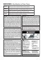
WARNING: If the information in these instructions is not followed exactly, a fire or
explosion may result causing property damage, personal injury or death.
FOR YOUR SAFETY: Do not store or use gasoline or other flammable vapors and
liquids in the vicinity of this or any other appliance.
WHAT TO DO IF YOU SMELL GAS:
• Do not try to light any appliance.
• Do not touch any electrical switch; do not use any phone in your building.
• Immediately call your gas supplier from a neighbor's phone. Follow the gas
supplier's instructions.
• If you cannot reach your gas supplier, call the fire department.
Installation and service must be performed by a qualified installer, service agency or
the gas supplier.
This manual should be maintained in legible condition and kept adjacent to the heater or in a safe place for future
reference.
Catalog No. 3000.50G
Effective: 04-08-09
Replaces: 05-06-08
P/N 240687 Rev. 8
Rev. 8 reflects the following: Changes to: Paragraph 3 of the GENERAL SPECIFICATIONS section on page 6; Fig. 7 on
page 12; the Wiring Diagrams on pages 14 and 15; Fig. 8 on page 16; Fig. 12 on page 19; Fig. 15 on page 20; the TROUBLESHOOTING chart on page 23. The addition of: A note to Fig. 2 on page 7.
2
CONTENTS
WARNINGS
4
Pay Attention to These Terms
4
GENERAL SAFETY
5
Time/Temperature Relationships in Scalds 5
RECEIVING EQUIPMENT
6
GENERAL SPECIFICATIONS
6
INSTALLATION
8
Code Requirements
8
Mounting Base
8
Clearances
8
Combustion & Ventilation Air
8
Venting Connections
9
Gas Supply Connections
11
Water Connections & System
Piping
12
Electrical Wiring
13
Wiring Diagram—Standing Pilot—Models
0090, 0135 & 0195
14
Wiring Diagram—IID—Models 0090,
0135 & 0195
15
SERVICING PROCEDURES
16
Sequence of Operation
16
Start-up Procedures
16
Repair Section
22
TROUBLESHOOTING
23
ADJUSTMENTS & REPLACEMENT
OF COMPONENTS
25
Gas Valve Replacement
25
Pilot Burner Cleaning or Replacement
(Standing Pilot)
25
Flame Roll-out Switch
Replacement
25
Vent Thermal Switch
Replacement
25
Ignition Module Replacement
25
Transformer Replacement
25
Circulator Replacement
26
Replacement Parts
26
WARRANTY
27
3
WARNINGS—Pay Attention to These Terms
DANGER:
Indicates the presence of immediate hazards which will cause severe
personal injury, death or substantial property damage if ignored.
WARNING:
Indicates the presence of hazards or unsafe practices which could cause
severe personal injury, death or substantial property damage if ignored.
CAUTION:
Indicates the presence of hazards or unsafe practices which could cause
minor personal injury or product or property damage if ignored.
NOTE:
Indicates special instructions on installation, operation, or maintenance which
are important but not related to personal injury hazards.
DANGER: Failure to install the draft hood and
properly vent the water heater to the outdoors as
outlined in the Venting section of this manual can
result in unsafe operation of the water heater. To
avoid the risk of fire, explosion, or asphyxiation from
carbon monoxide, never operate this water heater
unless it is properly vented and has an adequate air
supply for proper operation. Be sure to inspect the
vent system for proper installation at initial start-up;
and at least annually thereafter. Refer to the
Maintenance section of this manual for more
information regarding vent system inspections.
WARNING: Gasoline, as well as other flammable
materials and liquids (adhesives, solvents, etc.), and
the vapors they produce, are extremely dangerous.
DO NOT handle, use or store gasoline or other
flammable or combustible materials anywhere near
or in the vicinity of a water heater. Be sure to read
and follow the warning label pictured below and
other labels on the water heater, as well as the
warnings printed in this manual. Failure to do so can
result in property damage, bodily injury, or death.
WARNING: Propane appliances should not be
installed below-grade (for example, in a basement) if
such installation is prohibited by federal, state and/or
local laws, rules, regulations or customs.
DANGER: Water heaters utilizing propane gas are
different from natural gas models. A natural gas
heater will not function safely on propane gas and
vice versa. Conversion from Natural gas to propane
gas (or vice versa) must be done by a qualified
service technician. To avoid possible equipment
damage, personal injury or fire: DO NOT connect
this water heater to a fuel type not in accordance
with unit data plate. Propane for propane units,
Natural gas for natural gas units. These units are not
certified for any other type fuel.
DANGER: PROPANE MODELS: Propane gas must
be used with great caution.
• It is heavier than air and will collect first in lower
areas making it hard to detect at nose level.
• Make sure to look and smell for propane leaks
before attempting to light appliance. Use a soapy
solution to check all gas fittings and connections.
Bubbling at a connection indicates a leak that must
be corrected. When smelling to detect an propane
leak, be sure to sniff near the floor too.
• Gas detectors are recommended in propane applications and their installation should be in
accordance with the manufacturer's recommendations and/or local laws, rules, regulations or
customs.
• It is recommended that more than one method be
used to detect leaks in propane applications.
Vapors from
flammable liquids will
explode and catch fire
causing death or severe
burns.
Do not use or store flammable
products such as gasoline
solvents or adhesives in the
same room or area near the
water heater.
Keep flammable products:
1. far away from heater,
2. in approved containers,
3. tightly closed and
4. out of childrenʼs reach.
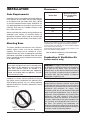
Installation:
Do not install water heater
where flammable products
will be stored or used unless
the main burner and pilot flames
Water heater has a main
burner and pilot flame.
The pilot flame:
1. is on all the time and
2. will ignite flammable
vapors.
Vapors:
1. cannot be seen,
2. are heavier than air,
3. go a long way on the
floor,
4. can be carried from other
room to the pilot flame by
their currents.
are at least 18" above the
floor. This will reduce, but
not eliminate, the risk of
vapors being ignited by the
main burner or pilot flame.
Read and follow water heater warnings and instructions. If owners
manual is missing, contact the retailer or manufacturer.
4
GENERAL SAFETY
Table A details the relationship of water temperature
and time with regard to scald injury and may be used
as a guide in determining the safest water temperature
for your applications.
To meet commercial hot water requirements, the tankstat is adjustable up to 190°F. However, water
temperatures over 125°F can cause severe burns
instantly or death from scalds. This is the preferred
starting point for setting the control for supplying general purpose hot water.
Safety and energy conservation are factors to be considered when setting the water temperature on the
tankstat. The most energy efficient operation will result
when the temperature setting is the lowest that satisfies the needs consistent with the application.
Temperature
Time to Produce Serious Burn
120°F
More than 5 minutes
125°F
1-1/2 to 2 minutes
130°F
About 30 seconds
135°F
About 10 seconds
140°F
Less than 5 seconds
145°F
Less than 3 seconds
150°F
About 1-1/2 seconds
155°F
About 1 second
Table courtesy of Shriners Burn Institute.
Table A: Time to Produce Serious Burn
Time/Temperature
Relationships in Scalds
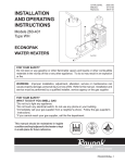
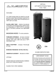
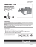
The temperature of the water in the storage tank can
be regulated by setting the temperature dial on front of
the tankstat. To comply with safety regulations, the
tankstat was set at its lowest setting before shipment
from the factory.
Water temperature over 125°F can
cause instant severe burns or death
from scalds.
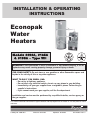
Fig. 1 illustrates the tankstat. To adjust the water temperature, insert a small straight screwdriver into slotted
screw in hole in front of tankstat and turn wheel to
desired setting. Thermostat is adjustable up to 190°F.
Children, disabled, and elderly are
at highest risk of being scalded.
See instruction manual before setting temperature at water heater.
Feel water before bathing or showering.
Temperature limiting valves are
available, see manual.
Maximum water temperatures occur just after burner
has shut off. To find hot water temperature being delivered, turn on a hot water faucet and place a
thermometer in the hot water stream and read the
thermometer.
Fig. 1: Tankstat Adjustment
5
DANGER: There is a Hot Water SCALD Potential if
the tankstat is set too high.
warranty conditions, you must also specify date of
installation.
CAUTION: Hotter water increases the risk of
SCALDING!
Raypak recommends that this manual be reviewed
thoroughly before installing your Raypak heater. If
there are any questions which this manual does not
answer, please contact your local Raypak representative.
NOTE: When this heater is supplying general
purpose hot water requirements for use by
individuals, a thermostatically controlled mixing
valve for reducing point of use water temperature is
recommended to reduce the risk of scald injury.
Contact a licensed plumber or the local plumbing
authority for further information.
GENERAL
SPECIFICATIONS
The Raypak water heaters are design certified by the
and tested under the requirements of the American
National Standard, ANSI Z21.10.3. Each heater has
been constructed and pressure tested in accordance
with the requirements of Section IV of the American
Society of Mechanical Engineers Code, and factory
fire tested.
RECEIVING EQUIPMENT
On receipt of your equipment it is suggested that you
visually check for external damage to the carton. If the
carton is damaged, it is suggested that a note be made
on the Bill of Lading when signing for equipment.
Remove the heater from the carton and if it is damaged report the damage to the carrier immediately. Be
sure that you receive the number of packages indicated on the Bill of Lading. Claims for shortages and
damages must be filed with carrier by consignee.
These heaters are designed for indoor and outdoor
installations, and can be installed on combustible flooring when the appropriate listed floor shield base is
used.
Models are available with standing pilot or with intermittent ignition device (IID), and are equipped with the
following components as standard: water circulation
pump, pressure relief valve, manual reset high limit
switch, flow switch, vent thermal and flame roll-out
switches, 40VA transformer, and redundant combination gas valve for use with either Natural or Propane
gases. A tankstat is supplied loose for installation in
the field.
Purchased parts are subject to replacement only
under the manufacturer's warranty. Debits for defective replacement parts will not be accepted and
defective parts will be replaced in kind only per our
standard warranties.
When ordering parts, you must specify Model and
Serial Number of the heater. When ordering under
6
Model
No.
Input Recovery Tank
(MBH)
(gph)
(Gal)**
Piping
Connections
(in.)
Water Gas
(NPT) (NPT)
Dimensions (in.)
A
B
K (Vent
Dia.)
WH-0090
90
90
80
1
1/2
11
5-3/4
5
WH-0135
135
132
80
1-1/4
1/2
18
6-1/4
6
WH-0195
195
192
80
1-1/4
1/2
18
6-1/4
7
Recovery gph based on manufacturer's rating.
**May be used with other tank size capacity.
Table B: Specifications and Dimensions
*
*Flow switch and temperature and pressure gauge must be field installed in the outlet water connection of the
heater.
Fig. 2: Dimensions
7
INSTALLATION
Clearances
Code Requirements
Installation must be in accordance with local codes, or,
in the absence of local codes, with the latest editions
of the National Fuel Gas Code, ANSI Z223.1,/NFPA
54, and the National Electrical Code, ANSI/NFPA 70.
In Canada installations must conform with the current
CAN/CSA B149 and the Canadian Electrical Code
Part 1 CSA C22.2 No.1.
Where required by the authority having jurisdiction, the
installation must conform to American Society of
Mechanical Engineers Safety Code for Controls and
Safety Devices for Automatically Fired Heaters, CSD1.
Heater Side
Minimum Distance
from Combustible
Surfaces
Floor
Combustible*
Front
Alcove**
Back
6 in.
Right
6 in.
Left
6 in.
Top (Indoor)
16 in.
Top (Outdoor)
Unobstructed
Flue Vent
6 in.
*Except for carpeted flooring, heaters are certified for installation on
combustible floors, when equipped with listed floor shield base.
**A front clearance of at least 24 in. is recommended for adequate
service of burner-tray and controls.
For uninsulated hot water pipes, maintain a 2 inch clearance, or consult the local authority having jurisdiction.
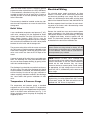
Mounting Base
This heater should be mounted on a level, non-combustible surface. Heater must not be installed on
carpeting. This heater can be installed on a combustible surface only when the appropriate listed floor
shield base is provided. An optional listed floor shield
base is available for factory installation with the heater
on all indoor models.
Table C: Minimum Clearances from Combustible
Surfaces
Combustion & Ventilation Air
(Indoor models only)
NOTE: The heater should be located in an area
where water leakage will not result in damage to the
area adjacent to the appliance or to the structure.
When such locations cannot be avoided, it is
recommended that a suitable drain pan, adequately
drained, be installed under the appliance. The pan
must not restrict air flow.
WARNING: Air supply to the heater room must not
be affected by mechanical exhaust vents located in
other parts of the house, such as kitchen or
bathroom fans, or attic blowers. Mechanical exhaust
vents may create a negative pressure condition in
the heater room that can become a hazard of
asphyxiation, explosion or fire.
In addition, the heater shall be installed such that the
gas ignition system components are protected from
water (dripping, spraying, rain, etc.) during appliance
operation and service (circulator replacement, control
replacement, etc.).
CAUTION: Combustion air must not be
contaminated by corrosive chemical fumes which
can damage the heater. Measures must be taken to
prevent the entry of corrosive chemical fumes to the
combustion and ventilation air supply. Such
chemicals include, but are not limited to, chlorinated
and/or fluorinated hydrocarbons such as found in
refrigerants, aerosol propellants, dry-cleaning fluids,
degreasers, and paint removers. Other harmful
elements may come from bleaches, air fresheners,
or mastics. Vapors from these types of products can
form corrosive acid compounds when burned in a
gas flame. The resulting acid condensate can
damage or substantially reduce the life of the heater.
It may be necessary to provide outside air directly to
the heater in order to avoid this problem.
Fig. 3: Do Not Install on Carpeting
8
1. The heater must be provided with adequate supply of air for proper combustion and ventilation in
accordance with Sec. 5.3 of the latest edition of
the National Fuel Gas Code, ANSI Z223.1, or
applicable provisions of the local building codes.
2. If the heater room is located against an outside
wall and air openings can communicate directly
with the outdoors, the TWO openings on the outside wall must each have a net free area, in
square inches as shown in Table D.
Model No.
Sq. in. of Each Free Area
0090
24
0135
35
0195
50
Model No.
Vent
Connector
Diameter (in.)
Max.
Horizontal
Length (ft)
0090
5
7.5
0135
6
9
0195
7
10.5
Table E: Vent Piping Specifications
For protection against rain or blockage by snow, the
vent pipe must terminate with a listed vent cap which
complies with the local codes or, in the absence of
such codes, to the latest edition of the National Fuel
Gas Code, ANSI Z223.1.
The discharge opening must be a minimum of two feet
vertically from the roof surface and at least two(2) feet
higher than any part of the building within ten (10) feet.
Vent stack shall be at least five (5) feet in vertical
height above the drafthood outlet. The vent cap location shall have a minimum clearance of four (4) feet
horizontally from, and in no case above or below,
unless a 4-foot horizontal distance is maintained, from
electric meters, gas meters regulators and relief equipment.
Table D: Minimum Net Free Area
Location of the openings is the same as in the previous case - that is, within 12 inches of the top,
and within 12 inches of the bottom of the enclosure. If horizontal ducts are used, the area must
be doubled and the duct area shall not be less
than the area of the openings they connect, and in
no case shall the smallest dimension be less than
3 inches.
The weight of the vent stack or chimney must not rest
on heater draft hood. Support must be provided in
compliance with applicable codes. The heater top and
draft hood must be readily removable for maintenance
and inspection. Vent pipe should be adequately supported to maintain proper clearances from combustible
construction.
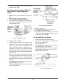
Venting Connections
Vent piping the same size or larger than the draft hood
outlet is recommended, however, when the total vent
height is at least ten (10) feet (draft hood relief opening to vent terminal), the vent pipe size may be
reduced as specified in the National Fuel Gas Code,
ANSI Z 223.1. As much as possible avoid long horizontal runs of vent pipe and too many elbows.
Type "B" double wall or equivalent vent pipe is recommended. However single wall metal vent pipe may be
used as specified in the latest edition of the National
Flue Gas Code ANSI Z223.1.
For connections to gas vents or chimneys, vent installations shall be in accordance with Part 7, Venting of
Equipment, of the National Fuel Gas Code, ANSI
Z223.1, or applicable provisions of the local building
codes.
If installation requires horizontal runs, the vent pipe
must have a minimum of 1/4 inch per foot rise and
should be supported at not more than five foot intervals. Plumbers tape, crisscrossed, will serve to space
both horizontal and vertical piping. Maximum vent connector horizontal length shall be 1-1/2 feet (18 inches)
for each inch of connector diameter as shown in Table
E.
Gas vents supported only by the flashing and extending above the roof more than five feet should be
securely guyed or braced to withstand snow and wind
loads. We recommend use of insulated vent pipe
spacer through the roofs and walls.
9
Fig. 5: Common Venting
(b) Visually inspect the venting system for proper size
and horizontal pitch and determine there is no
blockage or restriction, leakage, corrosion and
other deficiencies which could cause an unsafe
condition.
Fig. 4: Venting Minimum Clearances
(c) Insofar as is practical, close all building doors and
windows and all doors between the space in which
the appliances remaining connected to the common venting system are located and other spaces
of the building. Turn on clothes dryers and any
appliance not connected to the common venting
system. Turn on any exhaust fans, such as range
hoods and bathroom exhausts, so they will operate at maximum speed. Do not operate a summer
exhaust fan. Close fireplace dampers.
WARNING: These heaters must not be connected
into any portion of mechanical draft systems
operating under positive pressure. To do so may
cause the flue products to be discharged into the
living space causing serious health injury.
Common Vents
Manifolds that connect more than one heater to a common chimney must be sized to handle the combined
load. Consult available guides for proper sizing of the
manifold and the chimney. At no time should the
area be less than the area of the largest outlet.
(d) Place in operation the appliance being inspected.
Follow the lighting instructions. Adjust tankstat so
appliance will operate continuously.
(e) Test for spillage at the draft hood relief opening
after 5 minutes of main burner operation. Use the
flame of a match or candle, or smoke from a cigarette, cigar or pipe to visually check spillage.
At the time of removal of an existing heater, the following steps shall be followed with each appliance
remaining connected to the common venting system
placed in operation, while the other appliances remaining connected to the common venting system are not
in operation.
(f) After it has been determined that each appliance
remaining connected to the common venting system properly vents when tested as outlined above,
return doors, windows, exhaust fans, fireplace
dampers and any other gas burning appliance to
their previous conditions of use.
(a) Seal any unused openings in the common venting
system.
10
(g) Any improper operation of the common venting
system should be corrected so the installation
conforms with the latest edition of the National
Fuel Gas Code, ANSI Z223.1. When re-sizing any
portion of the common venting system, the common venting system should be re-sized to
approach the minimum size as determined using
the appropriate tables in Chapter 10 and in
Appendix G of the National Fuel Gas Code, ANSI
Z223.1 and CAN/CSA-B149.
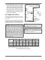
Gas Supply Connections
The inlet gas connection to the heater gas valve is
1/2". Provide an adequate gas supply line according to
Table F below.
SUPPLIED BY
INSTALLER
Gas piping must have a sediment trap ahead of the
heater gas controls, and a manual shut-off valve located outside the heater jacket. All gas piping should be
tested after installation in accordance with local codes.
Fig. 6: Sediment Trap
NOTE: Do not use teflon tape on gas line pipe
thread. A flexible sealant suitable for use with Natural
and Propane gases is recommended.
CAUTION: The heater and its manual shut off
valve must be disconnected from the gas supply
during any pressure testing of that system at test
pressures in excess of 1/2 psi (3.45 kPa). Dissipate
test pressure in the gas supply line before
reconnecting the heater and its manual shut off valve
to gas supply line. FAILURE TO FOLLOW THIS
PROCEDURE MAY DAMAGE THE GAS VALVE.
OVER PRESSURED GAS VALVES ARE NOT
COVERED BY WARRANTY. The heater and its gas
connections shall be leak tested before placing the
appliance in operation. Use soapy water for leak test
DO NOT use open flame.
1/2 in.
NOTE: These heaters are also certified to operate
on Propane gas, when equipped with the
combination gas valve and orifices (pilot and main
burners) sized for Propane gas.
3/4 in.
1 in.
1-1/4 in.
Model No.
Nat
Pro
Nat
Pro
Nat
Pro
0090
30
80
125
300
400
560
0135
15
40
60
150
150
200
20
35
70
100
100
0195
Natural gas, 1000 BTUH/ft .60 specific gravity @ 0.5 in. WC pressure drop.
Propane gas, 2500 BTUH/ft 1.53 specific gravity @ 0.6 in. WC pressure drop.
Table F: Maximum Equivalent Pipe Length (ft)
11
Nat
400
Pro
Water Connections & System
Piping
Gas Pressure Specifications
Inches WC
Type of
Gas
Min.
Max.*
Regulator
Setting
Natural
4.5
10.5
3.5
Propane
12.0
13.0
11.0
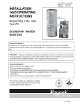
The pipe size and fittings between the heater and the
tank should be at least 1" for model 0090, and 1-1/4"
for models 0135 and 0195. This is based on the tank
being located as close to the heater as possible, as
shown in Fig. 7 below.
*Do not exceed maximum inlet gas pressure. The minimum value
shown is for input adjustment.
If this water heater is installed in a closed water supply
system, such as one having a back-flow preventer in
the cold water supply line, means shall be provided to
control thermal expansion. Contact the water heater
supplier or local plumbing inspector on how to control
this situation.
Table G: Gas Pressure Specifications
Gas Pressure Regulator
The gas valve is provided with pressure taps to measure gas pressure upstream of the gas valve and
downstream which is the same as the manifold pressure.
Fig. 7: Heater with Storage Tank
12
Electrical Wiring
When this water heater system is supplying general
purpose hot water requirements for use by individuals,
a thermostatically controlled mixing valve is recommended to reduce the risk of scald injury. Contact a
licensed plumber or the local plumbing authority for
further information.
The electrical power supply requirement for these
heaters is 120 volts, 60 Hz. Field wiring connections
and electrical grounding must comply with the local
codes, or in the absence of local codes, with the latest
edition of the National Electrical Code, ANSI/NFPA 70.
Thermometer(s) should be installed so that they indicate the water temperature at or near the outlet of the
storage tank.
Provide a separate fused circuit from the main electrical panel to the heater, and a disconnecting means
within sight of the heater.
Relief Valve
Remove the control box cover and make the power
supply connections in the field wiring compartment.
(See general location of controls drawing). The pump
is supplied and factory wired to operate with the
heater. The thermostat (tankstat) is shipped loose to
be installed in the tank at the installation site.
A new combination temperature and pressure (T & P)
relief valve, complying with the Standard for Relief
Valves and Automatic Gas Shut Off Devices for Hot
Water Supply Systems, ANSI Z21.22, must be
installed in the opening provided on top of the storage
tank, at the time of installation. No valve is to be placed
between the relief valve and the storage tank.
WARNING: SHOCK HAZARD: Line voltage is
present. Before servicing tankstat or heater, turn off
electrical power to the heater at the main disconnect
or circuit breaker. Failure to do so could result in
severe personal injury or death.
The pressure rating of the relief valve must not exceed
the 160 maximum working pressure indicated on the
water heater rating plate. The BTUH rating of the relief
valve must not be less than the BTUH input of the
heater.
Connect the outlet of the relief valve to a suitable open
drain. The discharge line must pitch downward from
the valve to allow complete draining (by gravity) of the
relief valve and discharge line.
NOTE: Minimum 18 AWG, 105°C, stranded wire
must be used for all low voltage (less than 30 volts)
external connections to the unit. Solid conductors
should not be used because they can cause
excessive tension on contact points. Install conduit
as appropriate. All high voltage wires must be the
same size (105°C, stranded wire) as the ones on the
unit or larger.
The discharge line should be no smaller than the outlet of the valve. The end of the discharge line should
not be threaded or concealed, and should be protected from freezing. No valve of any type, restriction or
reducer coupling, should be installed in the discharge
line. Local codes shall govern installation of relief
valve.
NOTE: If it is necessary to replace any of the
original wiring, it must be replaced with 105°C wire or
its equivalent, except 150° black wire which must be
replaced with 150° wire or its equivalent.
Temperature & Pressure Gauge
The temperature and pressure gauge is standard
equipment on all hot water heaters. All temperature
and pressure gauges are shipped loose for field installation in the outlet water connection (see Fig. 7). All
fittings required to mount the gauge to the piping are
supplied by others.
13
Wiring Diagram—Standing Pilot—Models 0090, 0135 & 0195
14
Wiring Diagram—IID—Models 0090, 0135 & 0195
15
SERVICING
PROCEDURES
tor in the module produces a high voltage spark pulse
output that lights the pilot burner. If the pilot burner
does not light, the module will not energize the second
main valve and the burners will not light. Ignition spark
continues only until the timed trial for ignition period
ends.
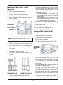
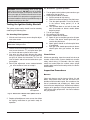
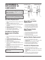
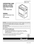
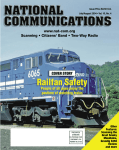
General Location of Controls
Then, the module goes into safety shutdown or lockout. Lockout de-energizes the first main valve operator
and closes the first main (pilot) valve in the gas control, stopping pilot gas flow. The ignition control system
must be reset by setting the tankstat below water temperature for one minute or by turning off power to the
module for one minute.
Circulator
Manual Reset Limit
(in heater behind panel)
When the pilot flame is established, flame rectification
circuit is completed between the sensor and burner
ground. The flame sensing circuit in the module
detects the flame current, shuts off the spark generator and energizes the second main valve operator
which opens the second main valve. This allows gas to
flow to the burners where it is ignited by the pilot burner flame.
Pressure
Relief Valve
Field Wiring
Compartment
Temperature Sensor
Ignition Module
When the tankstat is satisfied, the valve operators are
de-energized shutting off the pilot and main burners,
and also the circulator.
(Auto Ignition Only)
Transformer
Roll-Out Sensor
Gas Valve
Start-up Procedures
Fig.# 8195.3
Filling the System
Fill system with water. Purge all air from the system
using purge valve sequence. After system is purged of
air, lower system pressure. Flush system before putting into operation to ensure that foreign material does
not damage pump seals.
Ignition Module
(Auto Ignition Only)
Checking the Circulator
Fig. 8: General Location of Controls
Before lighting the heater and after system is filled,
make sure that circulator is operating properly. Manual
gas valve should be off.
Sequence of Operation
Intermittent Ignition Device (IID)
NOTE: Circulator motor supplied with the heater
does not require lubrication.
Heaters equipped with the IID system will automatically light the pilot burner first and then the main burner,
each time there is a call for heat from the tankstat.
Whenever the tankstat calling for heat, the circulator
supplied with the heater, will be energized and should
be running.
The ignition control module will also be energized to
initiate the pilot ignition by opening the first main valve
(pilot). At the same time, the electronic spark genera16
For Standing Pilot Model with
Robertshaw Gas Valve, On/Off
Operation
1.
2.
3.
4.
5.
9. Push in control knob all the way and hold in,
immediately light the pilot with a match. Continue
to hold control knob in for about one minute after
the pilot is lighted, release knob and it will pop
back up. Pilot should remain lighted. If it goes out,
repeat steps 4 through 8.
* If knob does not pop up when released, stop
and immediately call your service technician
or gas supplier.
* If the pilot does not stay lit after several tries,
turn the gas control knob to "OFF" and call
your service technician or gas supplier.
10. Stand to the side of the heater and turn the gas
STOP! Read the safety information.
Set the tankstat on the lowest setting.
Turn OFF all electric power to the heater.
Remove heater door panel.
Push in gas control knob slightly and turn clockwise
to "OFF".
control knob counter-clockwise
to "ON".
11. Replace heater door.
12. Turn "ON" all electrical power to the heater.
13. Set the tankstat to the desired setting.
GAS CONTROL
KNOB SHOWN
IN "OFF" POSITION
GAS INLET
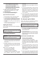
For Standing Pilot Model with
Honeywell Gas Valve, On/Off
Operation
Fig. 9: Robertshaw Gas Valve
1.
2.
3.
4.
NOTE: Knob cannot be turned from "PILOT" to
"OFF" unless knob is pushed in slightly. Do not force.
STOP! Read the safety information.
Set the tankstat to the lowest setting.
Turn Off all electrical power to the heater.
Remove heater door panel.
5. Turn gas control knob clockwise
6. Wait five (5) minutes to clear out any gas. Then
smell for gas, including near the floor. If your smell
gas, STOP! Follow "B" in the safety information
above on this label. If you don't smell gas, go to
the next step.
7. Locate pilot behind gas valve mounted on the
base panel of the burner drawer.
to "OFF".
GAS CONTROL
KNOB SHOWN
IN "OFF"
POSITION
GAS INLET
8. Turn knob on gas control counter-clockwise
to "Pilot".
Fig. 11: Honeywell Gas Valve
6. Wait five (5) minutes to clear out any gas. Then
smell for gas, including near the floor. If you smell
gas, STOP! Follow "B" in the safety information
above on this label. If you don't smell gas, go to
the next step.
7. Locate pilot behind gas valve mounted on the
base panel of the burner drawer.
HONEYWELL PILOT
8. Turn knob on gas control counter-clockwise
to "PILOT".
9. Push down and hold the red reset button in, immediately light the pilot with a match. Continue to hold
down red reset button for about one minute after
the pilot is lighted. Release red reset button and it
will pop back up. Pilot should remain lighted. If it
goes out, repeat steps 4 through 8.
ROBERTSHAW PILOT
Fig. 10: Honeywell and Robertshaw Pilots
17
10.
11.
12.
13.
* If red reset button does not pop up when
released, STOP and immediately call your
service technician or gas supplier.
* If the pilot does not stay lit after several tries,
turn the gas control knob to "OFF" and call your
Service technician or gas supplier.
Stand to the side of the heater and turn the gas
control knob counterclockwise
to "ON".
Replace heater door.
Turn "ON" all electrical power to the heater.
Set the tankstat to the desired setting.
•
instructions.
If you cannot reach your gas supplier, call the fire
department.
C. Use only your hand to push in, move or turn the
gas control knob or lever. Never use tools. If the
knob or lever will not push in, move or turn by
hand, don't try to repair it, call a qualified service
technician. Force or attempted repair may result in
a fire or explosion.
D. Do not use this heater if any part has been under
water. Immediately call a qualified service technician to inspect the heater and to replace any part
of the control system and any gas control which
has been under water.
System Shut Down Procedure
1. Set the tankstat to "OFF" or the lowest setting.
2. Turn off all electric switches to the heater.
3. Turn off all gas valves supplying gas to the heater.
Refer to operating instruction label on the heater.
4. Shut off the water supply to the heater piping system loop.
5. Open drain valve on the tank to remove water from
the heater and the piping circuits.
For Automatic Ignition Models
Please read carefully and understand the following
safety information before operating the heater.
WARNING: If you do not follow these instructions
exactly, a fire or explosion may result causing property damage, personal injury or loss of life.
Lighting the Heater
For your safety read carefully before proceeding to
light the heater.
A. This heater is equipped with an ignition device
which automatically lights the pilot. Do not try to
light the pilot by hand.
CAUTION: Propane gas is heavier than air and
sinks to the ground. Exercise extreme care in lighting heater in confined areas.
B. BEFORE OPERATING smell all around the heater
area for gas. Be sure to smell next to the floor
because some gases are heavier than air and will
settle on the floor.
For Standing Pilot Models
WARNING: If you do not follow these instructions
exactly, a fire or explosion may result causing property damage, personal injury or loss of life.
WHAT TO DO IF YOU SMELL GAS:
•
•
•
•
A. This heater has a pilot which must be lighted by
hand. When lighting the pilot, follow these instructions exactly.
•
B. BEFORE LIGHTING smell all around the heater
area for gas. Be sure to smell next to the floor
because some gas is heavier than air and will settle on the floor.
Do not try to light any appliance.
Do not touch any electric switch.
Do not use any phone in your building.
Immediately call your gas supplier from a neighbor's phone. Follow the gas supplier's instructions.
If you cannot reach your gas supplier, call the fire
department.
C. Use only your hand to push in, move or turn the
gas control knob or lever. Never use tools. If the
knob or lever will not push in, move or turn by
hand, don't try to repair it, call a qualified service
technician. Force or attempted repair may result in
a fire or explosion.
WHAT TO DO IF YOU SMELL GAS
• Do not try to light any appliance.
• Do not touch any electric switch.
• Do not use any phone in your building.
• Immediately call your gas supplier from a neighbor's telephone. Follow the gas supplier's
D. Do not use this heater if any part has been under
water. Immediately call a qualified service technician to inspect the heater and to replace any part
18
of the control system and any gas control which
has been under water.
GAS CONTROL
KNOB SHOWN
IN "OFF"
POSITION
For Intermittent Ignition (IID) with
Honeywell or Robertshaw Gas
Valve
GAS INLET
1. STOP! Read the safety information above on this
label.
2. Set the tankstat on the lowest setting.
3. Turn off all electric power to the appliance.
4. This appliance is equipped with an ignition device
which automatically lights the pilot. Do not try to
light the pilot by hand.
ROBERTSHAW
(All Models)
Fig. 13: Honeywell Gas Valve
GAS CONTROL
KNOB SHOWN
IN "ON"
POSITION
9.
10.
11.
12.
GAS INLET
HONEYWELL
(Model 0090)
Replace door panel.
Turn on all electric power to the appliance.
Set tankstat to desired setting.
If the heater will not operate, follow the instructions
“To Turn Off Gas To Appliance” and call your service technician or gas supplier.
To Turn Off Gas to Heater
Fig. 12: Honeywell Gas Valve
1. Set the thermostat to the lowest setting.
2. Turn off all the electric power to the appliance if
service is to be performed.
3. Remove door panel.
4. For Robertshaw Gas Valve: Push in and move
gas control lever to “OFF” position.
For Honeywell Gas Valve: Push in gas control
knob slightly and turn clockwise
to “OFF”.
5. Replace heater door panel.
5. Remove heater door panel.
6. For Robertshaw Gas Valve: Turn gas control knob
clockwise
to "OFF". For Honeywell Gas
Valve: Turn gas control knob clockwise
to
"OFF". Make sure knob rest against stop. For
Honeywell Gas Valve: Push in gas control knob
slightly and turn clockwise to "OFF". Knob cannot
be turned to "OFF" unless knob is pushed in slightly. Do not force.
7. Wait five (5) minutes to clear out any gas. Then
smell for gas, including near the floor. If you smell
gas, STOP! Follow "b" in the safety information
previously stated. If you do not smell gas, go to the
next step.
8. For Honeywell Gas Valve: Turn gas control knob
counter-clockwise
to “ON”.
For Robertshaw Gas Valve: Move gas control
lever to “ON" position.
Fig. 14: Honeywell Pilot
19
For Automatic Ignition Systems
CAUTION: Should overheating occur or the gas
supply fails to shut off, DO NOT turn off or disconnect the electrical supply to the pump. Instead, shut
off the gas supply at a location external to the heater.
Failure to observe this precaution may aggravate the
overheated condition resulting in possible damage to
the heater and injury to the user.
1. Turn on power to the ignition systems and turn gas
supply off at the gas valve.
2. Check ignition module as follows:
a. Set the tankstat to high setting.
b. Watch for continuous spark at the pilot burner.
c. Time the spark operation. Time must be within the lockout timing period (15 or 90
seconds).
d. Turn tankstat down to end call for heat and
wait 60 seconds on lockout models before
beginning step 3.
3. Turn on gas supply.
4. Set tankstat to high setting.
5. Systems should start as follows:
a. Spark will turn on and pilot gas valve will open
at once. Pilot burner should ignite after gas
reaches the pilot burner.
b. Spark ignition should cut off when pilot flame
is established.
c. Main gas valve should open and main burner
should ignite after gas reaches the burner
port.
Testing the Ignition Safety Shut-off
The ignition system safety shutoff must be tested by
conducting the following tests:
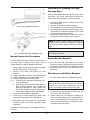
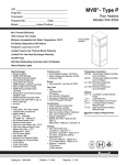
For Standing Pilot Systems
1. With the main burners on, remove the pilot adjustment cover screw.
NOTE: There is no pilot adjustment cover on
Robertshaw 7200 gas valve.
2. Insert a small slot screw driver and turn the adjustment screw clockwise
until pilot flame goes
out. Count and note number of turns made.
3. Gas valve will shut off main burners after about
three (3) minutes. End of test. If the gas valve will
not shut off, follow the instructions "To Turn Off
Gas To Heater" and call service technician or your
gas supplier.
4. Return pilot adjustment screw counterclockwise
same number of turns as in step 2.
Flame Failure
With burner operating, close the manual fuel valves to
simulate a flame failure. System should lock out after
safety switch timing (15 seconds). After the safety
switch has cooled, open the manual valves (relight
standing pilots) and reset the safety switch; the burner
should restart.
Inspection Procedures
1
2
3
Burners
S
E
T
PILOT P
I
ADJ
L
O
T
O
N
O
F
F
Clean main burners and air louvers of dust, lint and
debris. Keep heater area clear and free from combustibles and flammable liquids. Do not obstruct the
flow of combustion and ventilating air. Make visual
check of burner and pilot flame. Yellow flame indicates
clogging of air openings. Lifting or blowing flame indicates excess high gas pressure. Low flame indicates
low gas pressure.
PILOT KEY
Pilot Adjustment
Fig. 15: Robertshaw 7200 Gas Valve (Models 0135 &
0195)
5. Replace pilot adjustment cover screw, then follow
the lighting instructions to get heater ready for
operation.
20
Procedure for Cleaning Flue Gas
Passage Ways
Soot will clog areas behind fins and eventually cause
tube failure. Any sign of soot at base of burners or
around outer jacket indicates a need for cleaning.
1. Lift off draft hood and flue collector by removing
bolts and screws.
2. Remove "V" baffles from heat exchanger.
3. Remove burner tray, see Burner Drawer Removal.
4. Take garden hose and wash heat exchanger, making sure soot is removed from between fins. (Avoid
excessive water against refractory).
5. Reassemble; when heater is fired, some steam
will form from wet refractory, which is normal.
Fig. 16: Typical Main Burner Flame
NOTE: In extreme cases it may be necessary to
remove the heat exchanger completely for cleaning.
The simplest method is steam cleaning at a local car
wash.
CAUTION: Soot is combustible. Exercise extreme
care. Do not wire brush.
Fig. 17: Pilot Burner Flame (STG Pilot Units)
Normal Inspection Procedures
Burner Drawer Removal
First and third month after initial start up and then on
an annual basis. If problems are found, refer to
Trouble Shooting Guide for additional directions.
1. Shut off power and gas supply to the heater.
Disconnect union(s) and pilot tubing when present;
then loosen and remove burner hold down screws.
2. Disconnect wires at gas valve and slide burner
drawer out.
1. Remove top of heater and inspect heat exchanger
for soot and examine venting system.
2. Remove rear header and inspect for scale
deposits.
*3. Inspect pilot and main burner flame and firing rate.
*4. Inspect and operate all controls and gas valve.
*5. Visually inspect system for water leaks.
*6. a. Oil pump motor and bearing assembly, if oil
cups are provided.
b. Disconnect pump from header and check condition of pump impeller. Check condition of
bearing by attempting to move impeller from
side to side. Replace any parts showing wear.
c. Check pump coupler for wear and vibration.
7. Check flow switch paddle (if provided).
8. Clean room air intake openings to assure adequate flow of combustion and ventilation air.
Main Burner and Orifice Removal
1. Remove screws and burner hold down bracket.
NOTE: If the heat exchanger is sooted badly, the
burner hold down bracket and spacer can become
distorted from direct flame impingement and this
usually necessitates replacement of these parts.
2. Lift burners from slotted spacer and slide from orifices. Clean with a wire brush.
3. Orifices usually do not need to be replaced. To
clean, run either copper wire or wood through orifice. Do not enlarge hole. To remove orifice, use a
socket wrench and remove the manifold. DO NOT
overtighten when reinstalling.
9. Keep heater area clear and free from combustible
materials, gasoline, and other flammable vapors
and liquids.
*Should be checked monthly. (Takes approximately 15
minutes).
21
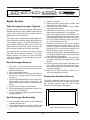
RAYPAK TUBE CLEANING KIT
Extension Pieces (5)
Auger with Carbide Tip
Wire Brush
Fig. 18: Raypak Tube Cleaning Kit
Repair Section
3. Replace "V" baffles.
4. Install thermostat sensing bulbs in header wells
and replace bulb retaining clips.
5. Install inlet and return pipes in water headers
using pipe thread sealant.
6. Install water pressure relief valve, sensor probe,
and low water cutoff devices if so equipped.
7. Open water supply and return shut-off valves. Fill
heater and water piping system with water. Check
heater and piping system for leaks at full line pressure. Run system circulating pump for a minimum
of 1/2 hour with heater shut-off.
8. Shut down entire system and vent all radiation
units and high points in system piping. Check all
strainers for debris. Expansion tank water level
should be at the 1/4 mark and the balance of the
tank filled with air (when using Air-X-Tank).
9. Install flue collector, jacket top and inspection panels. Install top holding screws. Install draft diverter
and vent piping if so equipped.
10. If gas piping was disconnected, reconnect gas piping system and check for leakage using a soap
solution.
11. Check for correct water pressure and water level
in the system. Make sure that system pump operates immediately on the call for heat. The system
is ready for operation.
12. Within two (2) days of start-up, recheck all air
vents and expansion tank levels.
Tube Cleaning Procedure (Typical)
Establish a regular inspection schedule, the frequency
depending on the local water condition and severity of
service. Do not let the tubes clog up solidly. Clean out
deposits over 1/16" in thickness.
The heater may be cleaned from the side opposite the
water connections, without breaking pipe connections.
It is preferable, however, to remove both headers for
better visibility through the tubes and to be sure the
residue does not get into the system. Generally, you
do not remove the top pan or the heat exchanger .
After reaming with the auger, mount the wire brush
and clean out the debris remaining in the tubes.
Another method is to remove the heat exchanger,
ream tubes and immerse heat exchanger in non-inhibited de-scale solvent.
Heat Exchanger Removal
1. Shut water, gas and electricity off, close valves
and relieve pressure, remove relief valve. Remove
side inspection panels.
2. Remove top holding screws.
3. Remove draft diverter, lift and remove top and flue
collector on stack type models. Remove inspection panels.
4. Loosen bolts and disconnect flange nuts on inletoutlet header, loosen union(s) at gas pipe, and
slide heater away from piping until studs clear the
heater.
5. Remove heat exchanger corner brackets.
6. Remove combustion chamber clips at the four corners of the heat exchanger.
7. Lift heat exchanger straight up using caution not to
damage refractory.
Combustion Chamber Removal
To remove combustion chamber you must first have
removed the heat exchanger. Unbolt metal combustion chamber retainer from top and remove
combustion chamber panels individually.
Heat Exchanger Re-Assembly
1. Heat exchanger water header O-rings should be
replaced with new ones.
2. Install inlet-outlet and return water headers and
install header retainer nuts and torque nuts evenly.
Fig. 19: Refractory Panels—Top View
22
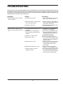
TROUBLESHOOTING
These instructions are primarily intended for the use of qualified personnel specifically trained and experienced in the
installation of this type of heating equipment and related system components. Installation and service personnel may
be required by some states to be licensed. Persons not qualified shall not attempt to install this equipment nor
attempt repairs according to these instructions.
PROBLEM(S)
1)When tankstat is turned on, heater
does not operate.
CAUSE(S)
1)No power to the heater.
SOLUTION(S)
1)Check circuit breakers, disconnect
switch. Make sure power is on.
2)Defective tankstat or disconnected
wire in thermostat circuit.
2)Check continuity on thermostat and
wiring circuit. Replace thermostat, or
repair wiring connections.
3) Check secondary voltage. If no 24V,
replace transformer.
3)Defective transformer.
2)When tankstat is calling for heat,
pump is on, but burners will not turn
on.
1) For Standing pilot models pilot burner
not lighted.
2) If pilot burner will not stay lighted,
thermocouple or gas valve may be
defective.
3)Gas knob in "Pilot" position.
4)Vent switch is open.
5)Roll-out switch is open.
6)Manual Reset High limit is open.
7) Defective ignition module or
defective gas valve.
23
1) Light pilot burner. (Follow lighting
instructions on rating plate).
2) Check thermocouple MV generation.
If less than 25MV (open circuit), replace thermocouple. If between 2535 MV, replace gas valve.
3) Turn knob to "ON" position.
4) Check for blockage of venting sys
tem or disconnected vent piping. After
problem is corrected push button to
reset vent switch.
5) Check for blockage of flue or sooted
heat exchanger. After problem is
corrected push button to reset
roll-out switch.
6) Check water flow and adjust to
obtain 8° to 10°F temperature rise.
7)On Honeywell module, check voltage
across terminals MV and MV/PV. If
no 24V is present, replace module. If
24V is present, replace gas valve.
3)Pilot Outage.
(Standing pilot models)
1) Too low or too high gas
pressures.
2) Restricted pilot.
3) Weak thermocouple.
1) Adjust inlet gas pressure as
shown on rating plate.
2) Clean pilot orifice.
3) Replace thermocouple.
4)Yellow lazy flame.
1) Too low gas pressure.
1) Adjust manifold pressure as
2) Restricted burner intake ports.
3) Restricted gas line.
5)Sooting
1) Insufficient combustion air.
2) Improper venting.
3) Severe yellow burner flames.
24
shown on rating plate.
2) Clean burners free of debris or
insects.
3) Clean gas line or increase gas line
piping.
1) Refer to installation instructions
regarding combustion air
requirements.
2) Refer to installations instructions.
3) See yellow flame section above.
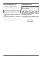
ADJUSTMENTS &
REPLACEMENT OF
COMPONENTS
HONEYWELL PILOT
PILOT
ROBERTSHAW PILOT
PILOT
AIR
OPENING
CAUTION: Label all wires prior to disconnection
when servicing controls. Wiring errors can cause
improper and dangerous operation. Verify proper
operation after servicing.
ORIFICE
ORIFICE
DANGER: SHOCK HAZARD: Make sure electrical power to the heater is disconnected to avoid
potential serious injury or damage to components.
Fig. 20: Pilots
Gas Valve Replacement
Flame Roll-out Switch
Replacement
1. Shut off electrical power and gas supply to the
heater.
2. Remove gas piping to gas valve inlet.
3. Disconnect wiring connections, pilot tubing (when
equipped).
4. Remove screws (2) holding the burner tray.
5. Slide burner tray out.
6. Remove gas valve bracket screws and bracket.
7. Unscrew gas valve from gas pipe.
8. Reverse above procedure to re-install.
1.
2.
3.
4.
Shut off electrical power to the heater.
Remove wiring connections to switch.
Remove screws (2) holding the switch.
Reverse above procedure to re-install.
Vent Thermal Switch
Replacement
Pilot Burner Cleaning or
Replacement (Standing
Pilot)
1.
2.
3.
4.
1. Shut off electrical power and gas supply to the
heater.
2. Disconnect gas piping to gas valve.
3. Disconnect wiring connections to gas valve.
4. Remove screws (2) holding the burner tray.
5. Slide burner tray out.
6. Remove screw holding pilot lighter tube.
7. Remove screws (2) holding pilot bracket on the
burner tray.
8. Disconnect thermocouple and pilot tubing from the
gas valve.
9. Remove pilot burner from pilot bracket.
10. Remove pilot orifice and blow away lint or dirt.
Clean with wire or small brush.
Shut off electrical power to the heater.
Remove wiring connections to switch.
Remove the screws (2).
Reverse above procedure to re-install.
Ignition Module Replacement
1. Shut off electrical power to the heater.
2. Remove control cover screws and open control
compartment.
3. Disconnect wiring connections to module.
4. Remove screws (2) holding module.
5. Reverse above procedure to re-install.
Transformer Replacement
1. Shut off electrical power to the heater.
2. Remove control cover screws and open control
compartment.
3. Disconnect wiring connections from transformer
leads.
4. Remove screws (2) holding transformer.
5. Reverse above procedure to re-install.
NOTE: Make sure pilot orifice is clear, but do not
enlarge the hole.
11. Reverse above procedure to re-install.
25
Circulator Replacement
Replacement Parts
1. Shut off electrical power to the heater.
2. Shut off water supply and open drain valve to
remove water in the piping at the pump level.
NOTE: To supply the correct part it is important that
you state the model number, serial number and type
of gas when applicable.
CAUTION: To avoid damage to electrical components keep water from getting into the control
compartments and gas valve.
Any part returned for replacement under standard
company warranties must be properly tagged with
RAYPAK return parts tag, completely filled in with the
heater serial number, model number etc., and shipped
to the Company freight prepaid.
3. Disconnect wiring and conduit connections to the
pump.
4. Remove the nuts and bolts at the inlet and outlet
flanges. Remove old gaskets.
5. Remove the pump.
6. Reverse the above procedure to re-install. Use
new gaskets and make sure they are seated properly when tightening the nuts and bolts.
If determined defective by the Company and within
warranty, the part will be returned in kind or equal substitution, freight collect. Credit will not be issued.
RAYPAK, INC.
2151 Eastman Avenue
Oxnard, CA 93030
26
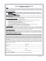
LIMITED PARTS WARRANTY ECONOPAK WATER HEATERS
MODELS WH - 0090 TO 0195
SCOPE:
Raypak, Inc. ("Raypak") warrants to the original owner that all parts of this water heater which are actually manufactured by Raypak
will be free from failure under normal use and service for the specified warranty periods and subject to the conditions set forth in this
Warranty. Labor charges and other costs for parts removal or reinstallation, shipping and transportation are not covered by this Warranty
but are the owner's responsibility.
HEAT EXCHANGER WARRANTY:
• Five (5) Years from date of water heater installation. This includes only the copper, bronze and cast iron waterways.
• Twenty (20) Years from date of water heater installation against "Thermal Shock" (excluded, however, if caused by operation
at large changes exceeding 150°F between the water temperature at intake and water heating temperature, or operating at water
heater temperatures exceeding 190°F).
ANY OTHER PART MANUFACTURED BY RAYPAK:
One (1) year warranty from date of installation, or eighteen (18) months from date of factory shipment based on Raypak's records,
whichever comes first.
SATISFACTORY PROOF OF INSTALLATION DATE, SUCH AS INSTALLER INVOICE, IS REQUIRED. THIS WARRANTY WILL BE VOID
IF THE WATER HEATER RATING PLATE IS ALTERED OR REMOVED.
ADDITIONAL WARRANTY EXCLUSIONS:
This warranty does not cover failures or malfunctions resulting from:
1. Failure to properly install, operate or maintain the water heater in accordance with our printed instructions provided;
2. Abuse, alteration, accident, fire, flood and the like;
3. Sediment or lime buildup, freezing, or other conditions causing inadequate water circulation;
4. High velocity flow exceeding water heater design rates;
5. Failure of connected systems devices, such as pump or controller;
6. Use of non-factory authorized accessories or other components in conjunction with the water heater system;
7. Failing to eliminate air from, or replenish water in, the connected water system;
8. Chemical contamination of combustion air or use of chemical additives to water.
PARTS REPLACEMENT:
Under this Warranty, Raypak will furnish a replacement for any failed part. The failed part must first be returned to Raypak if
requested, with transportation charges prepaid, and all applicable warranty conditions found satisfied. The replacement part will be
warranted for only the unexpired portion of the original warranty. Raypak makes no warranty whatsoever on parts not manufactured
by it, but Raypak will apply any such warranty as may be provided to it by the parts manufacturer.
TO MAKE WARRANTY CLAIM:
Promptly notify the original installer, supplying the model and serial numbers of the unit, date of installation and description of the
problem. The installer must then notify his Raypak distributor for instructions regarding the claim. If either is not available, contact Service
Manager, Raypak, Inc., 2151 Eastman Avenue, Oxnard, CA 93030 or call (805) 278-5300. In all cases proper authorization must first be
received form Raypak before replacement of any part.
EXCLUSIVE WARRANTY - LIMITATION OF LIABILITY:
This is the only warranty given by Raypak, No one is authorized to make any other warranties on Raypak's behalf. THIS WARRANTY
IS IN LIEU OF ALL OTHER WARRANTIES, EXPRESS OR IMPLIED, INCLUDING BUT NOT LIMITED TO IMPLIED WARRANTIES OF
MERCHANTABILITY AND FITNESS FOR A PARTICULAR PURPOSE. RAYPAK'S SOLE LIABILITY AND THE SOLE REMEDY AGAINST
RAYPAK WITH RESPECT TO DEFECTIVE PARTS SHALL BE AS PROVIDED IN THIS WARRANTY. IT IS AGREED THAT RAYPAK SHALL
HAVE NO LIABILITY, WHETHER UNDER THIS WARRANTY, OR IN CONTRACT, TORT, NEGLIGENCE OR OTHERWISE, FOR ANY SPECIAL,
CONSEQUENTIAL, OR INCIDENTAL DAMAGE, INCLUDING DAMAGE FORM WATER LEAKAGE. Some states do not allow limitations on how
long an implied warranty lasts, or for the exclusion of incidental or consequential damages. So the above limitation or exclusion may not
apply to you.
This Limited Warranty gives you specific legal rights. You may also have other rights which may vary from state to state. We suggest
that you complete the information below and retain this certificate in the event warranty service is needed. Reasonable proof of the
effective date of the warranty (date of installation) must be presented, otherwise, the effective date will be based on the rate of
manufacture plus thirty (30) days.
_____________________________________________________
Name of Owner
_____________________________________________________
Address
_____________________________________________________
____________________________________________________
Name of Dealer
____________________________________________________
Address
____________________________________________________
_____________________________________________________
Model No.
____________________________________________________
Serial No.
Date of Installation: _____________________________________
Date of Initial Operation: ________________________________
CORPORATE HEADQUARTERS:
RAYPAK, INC., 2151 Eastman Avenue, Oxnard, CA 93030 (805) 278-5300 FAX (805) 278-5489
Litho in U.S.A.
27
www.raypak.com
Raypak, Inc., 2151 Eastman Avenue, Oxnard, CA 93030 (805) 278-5300 Fax (805) 278-5468
Litho in U.S.A.