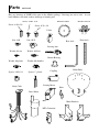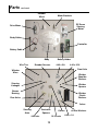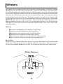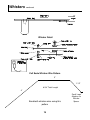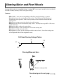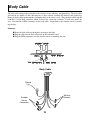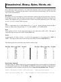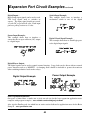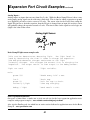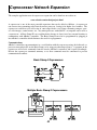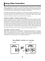
1
Mobile Robot
For Hobbyist, Research and
Education
Assembly and User Guide
Copyright (c) 2005 Arrick Robotics
All Rights Reserved
Robotics.com
ARobot Mobile Robot
Table of Contents
Introduction
Introduction....................................................1
About ARobot................................................1
What You’ll Need ..........................................2
Feature List ....................................................2
Specifications.................................................3
Precautions.....................................................4
Component Locator .......................................5
Glossary of Terms..........................................6
Assembly
Assembly Overview.......................................9
Parts................................................................10
Painting ..........................................................13
Whiskers ........................................................14
Drive Motor and Brackets..............................16
Encoder Sensor ..............................................17
Front Wheel Assembly ..................................18
Steering Motor and Rear Wheels...................19
Controller Board ............................................21
Battery Pack ...................................................22
Body Cable.....................................................23
Finishing Up...................................................24
Usage
About the Controller ......................................25
Basic Stamp II Installation.............................25
Cable to your PC............................................26
PC Editor/Downloader...................................26
The Test Program...........................................27
Steering Straightening Steering .....................27
Wander Program ............................................27
Controller Schematic .....................................28
Batteries .........................................................29
Power On/Off Switch.....................................29
Reset Button...................................................29
Whiskers ........................................................30
Speaker...........................................................30
LED Indicators...............................................30
Push Buttons and Jumpers .............................31
Drive Motor and Encoder ..............................31
Steering Motor ...............................................32
Coprocessor Command Summary .................33
Hexadecimal, Binary, Bytes, Words..............35
Revision D
11/17/2005
Table of Contents Continued
Connectors
Battery Connector ..........................................36
Body Connector .............................................36
Serial Port Connector.....................................36
RC Servo Motor Connectors..........................37
DC Motor Connector .....................................37
Powerful Output Connector ...........................37
Expansion
Expansion Connector .....................................38
User RC Servo Motors...................................38
Expansion Circuit Examples..........................39
Coprocessor Network Expansion...................42
Using Other Controllers.................................43
Additional Information
Suggested Reading.........................................44
Component/Accessory Suppliers ...................45
Internet Robot Resources...............................47
Troubleshooting .............................................49
Warranty Information ....................................50
ARobot Project Database – www.robotics.com/arobot/projects.html
ARobot FAQ – www.robotics.com/arobot/faq.html
Introduction
Congratulations for purchasing the ARobot mobile robot. This manual should answer all of your
questions. We suggest that you read and understand all of it before using your new robot. If you have
any questions, please view our web site at www.robotics.com/arobot
The software provided is designed for use with IBM-style personal computers. This manual assumes the
user has full understanding of how to use their computer and operating system. Refer to the
documentation for the computer for additional information.
ARobot is designed for the beginning robot hobbyist, but if it looks beyond your skill level, please
return the unit before going any further.
Parents: If you’re buying ARobot for a young person, be prepared to help them.
About ARobot
The ARobot (pronounced "A robot") is a computer controlled mobile robot designed for hobbyists and
educators. Ages 16 and up (younger if helped by an adult) can enjoy unlimited experimentation by
programming the on-board Basic Stamp II control computer. Learn and use concepts such as computer
programming, motion control, sensor reading, path planning, object avoidance, and more. Easily
assembled in a few hours using common hand tools (no soldering required). Connect ARobot to your
personal computer for programming and begin your adventure.
Basic Stamp II Control Computer
The Basic Stamp II is a small, self-contained computer controller manufactured by Parallax Inc. This
easy-to-use system is programmed using a Basic-like language called PBasic. Programs are written on
an IBM-style PC then downloaded to the Basic Stamp II for execution. Large libraries of programs can
be created and saved. ARobot'
s controller board accepts the Basic Stamp II (purchased separately)
which controls motors, LEDs, buzzer, and other devices. The Parallax Web site at
www.parallaxinc.com provides complete information about the Basic Stamp II including the
programming manual.
ARobot is a versatile system that can perform a variety of tasks. Here are just a few examples:
Hobby robotics projects.
Education and training.
Research in artificial intelligence, A-life, etc.
Science projects.
Testing platform for navigation algorithms.
Simulation of planetary exploration.
Maze solving.
Contests.
Publicity.
Fun, Fun, Fun!
1
What You’ll Need
To build and program ARobot you will need the following items:
Common hand tools – screwdriver, pliers, etc.
Your choice of spray paint (optional).
Basic Stamp II computer chip.
Basic Stamp II programming information – available free on the Internet or you can purchase a book.
Understanding of Basic programming or a willingness to learn.
IBM style PC running DOS or Windows, 3-1/2“ disk drive, unused serial port (9 pin connector).
Internet access for technical support and application notes.
8 AA batteries. (over 5 hours of continuous run time).
A never-ending desire to experiment and play with robots!
Note: Expansion may require knowledge of electronics, soldering and other advanced skills.
Feature List
The following list of features will help you get aquatinted with ARobot.
Safe, low voltage system.
Dimensions: 10" x 10", 5" tall, 2-1/4 lbs. Whiskers extend beyond these dimensions.
High quality machined aluminum frame (no plastic or wood).
Dual front whisker sensors.
Maximum speed: 10" per second.
Surfaces: Low pile carpet, tile, concrete, moderate bumps and inclines.
1 pound payload capacity for radio data link, embedded PC, accessories.
Removable battery pack uses 8 standard AA-cells or rechargeables.
5 hour or longer typical run time.
Socket accepts the popular Basic Stamp II controller.
Controllable Red and Green LEDs.
Sound output transducer.
Two user defined push button switches.
Two user defined jumper switches.
Rear wheel steering RC servo motor.
Front wheel DC gear drive motor.
Optical wheel encoder for distance measurement.
Second H-bridge for motor or power device control.
3 User defined RC servo motor control ports.
Serial communications port.
Program using a desktop PC then download for autonomous operation.
Expansion port allows unlimited possibilities.
Mounting holes for Radio Shack Breadboard or perfboard.
Coprocessor network allows multiple processors to communicate and distribute tasks.
Application notes for sonar range finding, head light, light sensors, compass, and more.
2
Technical Specifications
Body: .062 aluminum - cut, punched, and formed.
Configuration: 3-wheel, front wheel drive, rear wheel steer.
Dimensions: 10" x 10", 5" tall, 2-1/4 lbs.
Payload capacity: 1 lbs.
Wheel size: 3.25" diameter.
Drive Motor: 12 volt DC gear motor, 74 full load RPM, 1.6 amp full load current.
Quality machined wheel coupling and bearings.
Optical wheel encoder for distance measurement
Encoder: 20 counts per revolution - 2 per inch of travel (1/2” resolution).
Motor driver: H bridge - 1 amp max.
Speed control: Pulse Width Modulation.
Controller PCB size: 2.1" x 6"
Steering Motor: Standard size RC servo motor.
Power source: 8-AA cells in removable pack.
Runs on 8 AA-cell batteries for 5 hours or more.
Current draw: 50ma at standstill, 200ma with motor running typical.
Coprocessor: PIC16F84 for motor control.
Expansion connector - 40 pin (2x20) IDC .1 centers.
3
Precautions
The following precautions must be taken to insure trouble free operation of ARobot. The order that
these precautions are listed does not indicate their importance. Failure to observe these precautions may
result in loss of life, damage of property and/or damage to the Robot.
Never attach or remove cables while power is applied to the Robot.
Never use the robot in areas near water such as swimming pools.
Never allow the whisker wires to be inserted into electrical outlets or other dangerous places.
Never use the robot in areas that could result in a fall such as lofts, stairways, hills.
Never allow cables to fall out or to be broken by the robot'
s motion.
Never control devices with the robot that could be dangerous to life or property such as
lawn mowers or high power lasers.
Never connect the robot'
s controller to inappropriate equipment.
Never use the robot in situations where a programming error or other
malfunctions could cause damage to property or life.
Never exceed the specifications such as payload, incline, current drain, etc.
Failure to observe these
precautions may result in loss of
life, damage to property and/or
damage to the robot.
4
Component Locator
Use the following diagrams to familiarize yourself with ARobot'
s various components.
Encoder
Wheel
Front
Right Side
Whiskers
Drive
Motor
Controller
Battery
Pack
Steering
Motor
Steering
Arm
Steering
Linkage
Controller
Expansion
Connector
Proto Area
Body
Connector
RC Servo
Motors
Drive motor
Connector
Powerful
Output
Battery
Connector
Basic Stamp
Green LED
Red LED
Power
Switch
Coprocessor
Reset
Jumpers
Buttons
Serial Port
5
Speaker
H-bridge
5V Voltage
Regulator
Glossary of Terms
Analog Signals – Signals that have values between on and off (1 and 0).
Android – A robot that has a human-like form.
Artificial Intelligence (AI) – A computer program that simulates intelligence like that found in
biological systems.
Artificial Life – Behavior that is simulated by a computer program or other machine that mimics some
or all aspects of biological life.
Baud Rate – The number of bits per second. In a serial signal from a typical personal computer, the
baud rate is the number of bytes per second times 10. Each byte consists of 8 data bits, 1 start bit, and 1
stop bit.
BASIC – A high-level programming language.
Binary – A numbering system using 2 numbers – 1 and 0.
Bit – Abbreviation for binary digit. Each bit can have a value of 1 or 0.
Byte – A group of 8 bits.
C – A high-level programming language.
Cellular Automata – A system constructed with an array of cells where each cell can act according to
preset instructions and can respond to nearby cells. Once started the system proceeds without further
instructions.
Central Processing Unit (CPU) - The central component of a computer that executes instructions
written by a programmer and controls I/O devices and memory.
Chaos – Disorder displayed by some complex systems.
Closed Loop – In motor control, the use of a feedback device such as an encoder to adjust the motor
driver to achieve the desired position, speed, or acceleration. ARobot’s drive motors are closed loop.
Compiler – A program that converts a high-level program into a low-level program that can be executed
directly by a CPU.
Digital Signals – Signals that can have a value of on or off (1 or 0).
Encoder – A feedback device used by a motor to sense position and speed. Normally a wheel with
holes or slots that are detected with an optical sensor.
EEPROM – Electrically Erasable Programmable Read Only Memory. A type of memory IC that can
be written and read, and will retain data even after power is turned off. Used by the Basic Stamp to
store programs and parameters.
EPROM – Erasable Programmable Read Only Memory. A type of memory that can be read only, and
retains its data after power is turned off.
Emergent Behavior – Unexpected behavior in a robot that was not explicitly programmed.
Expert System – An intelligent system based on a database of rules.
Feedback – A signal produced by a sensor such as an encoder that is used to adjust motor position and/
or speed.
Finite State Machine (FSM) – A machine or program that has a limited number of states, can examine
its own state, can change its own state according to a set of rules, and can receive input from external
sources.
Firmware – Programs that are stored on EPROM such as the Basic Stamps PBasic interpreter.
6
Glossary of Terms
continued
Fractals – A geometric pattern in which an object looks the same regardless of the viewing scale.
Fractal concepts can be used in AI programming.
Fuzzy Logic – Logic in which boundaries between sets are not crisp. This concept is often used to
control systems that would be too complex to model with traditional sequential programs.
Genetic Algorithm – A set of instructions that mimic biological life by simulating genes, mutation, and
other aspects of living systems.
Gripper – A device that allows a robot to grasp objects.
Hardware – Physical circuitry including circuit boards, ICs (integrated circuits), transistors, etc.
H-Bridge – An arrangement of 4 transistors in the shape of the letter ‘H’ used to control the direction of
a DC motor. ARobot uses a single IC that contains 2 H-bridges to control the drive motor and powerful
output..
Hexadecimal – Base 16 numbering system. Each digit is written as 0-9,A-F. Hexadecimal makes it
easier to enter data and address values. Example of a hex byte is 4A, example of a hex word is A04F.
High-Level Language – A computer programming language that allows the user to create complex
programs using instructions that represent many simpler instructions. PBasic used by the Basic Stamp II
is a high level language.
Infrared (IR) - Electromagnetic radiation generated by thermal agitation. IR is invisible to the human
eye. IR is used by most TV and Stereo remote controls. Also see Passive Infrared
Integrated Circuit (IC) - A device where many electrical components are built together as a single
component. ARobot uses integrated circuits on it’s circuit boards to perform most functions.
Interpreter – A computer language that converts instructions while the program is running. Unlike a
compiler that first converts the program to machine code. Interpreters are normally slower than
compilers.
Joystick – A control device that employs a stick to achieve 2 axis control.
Laws of Robotics - Three laws written by Isaac Asimov which prevent robots from intentionally
harming humans and set other task priorities.
A robot may not injure a human being or, through inaction, allow a human
being to come to harm
A robot must obey the orders given it by human beings except where such
an order would conflict with the First Law.
A robot must protect its own existence as long as such protection does not
not conflict with the First or Second Law.
Light Emitting Diodes (LED) - Semiconductor that gives off light.
Liquid Crystal Display (LCD) - A type of display that can be controlled electrically and uses minimal
power. Many calculators use LCD type displays.
Loops – In a computer program, the re-execution of instructions using control flow statements such as
GOTO and WHILE.
Low-Level Language – The set of instructions used directly by a CPU to perform operations. Often
referred to as assembly language.
7
Glossary of Terms
continued
Mechatronics – A combination of mechanical and electrical devices to create a system.
Natural Language – Language used by humans to communication.
Neural Network – A network of processing elements that are connected together to simulate the intelligence created by biological brains. Often used to perform pattern recognition.
Open Loop – in motor control, the lack of a feedback device.
Parallel Data – Data that is transmitted multiple bits at a time using multiple wires.
Parameters – Values used to control functions.
Passive Infrared (PIR) sensor - A type of sensing device that converts infrared energy into electrical
signals. Motion detectors for alarm systems often use PIR sensors to detect moving living objects.
PC/104 – Embedded computer system standard which has connectors with 104 pins. PC/104 modules
are similar to cards found in desktop personal computers except that they stack together instead of plugging into a mother board. Complete computer systems can be created using PC/104 products.
Printed Circuit Board (PCB) - A non-conductive board that is laminated with layers of copper to provide electrical connections between components. ARobot’s controller is a PCB.
Pulse Width Modulation (PWM) - In motor control, the use of electrical pulses of various widths to
control the motor’s position and speed. In speech and sound creation, the use of various pulse widths to
generate an analog signal by using a low-pass filter.
RAM – Random Access Memory. Read/write memory.
Remote Control – Control of a system at a distance.
Resolution – In a motor control system, the smallest motion that a motor can make.
Robot – Any device that operates automatically performing tasks like a human.
Rule-based System – See Expert Systems.
Sensor – A device that converts light, temperature, and other phenomena to electrical signals. Also referred to as transducer. The ARobot uses many different sensors to detect the environment.
Serial Data – Data that is transmitted a signal bit at a time over one wire.
Servo Motors RC, DC – DC (direct current) servo motors use encoder feedback to monitor speed and
position such as ARobot’s drive motor. RC (remote control) servo motors are small servo systems that
include motor, gear train, feedback device, and controller in a small package intended for remote control
airplanes and cars. RC servos are used by ARobot to control the steering.
Software – Instructions used to direct operations on a CPU.
Sonar – See Ultrasonic.
Speech Synthesizer – An electronic device that generates human speech and sounds.
Subsumption Architecture – A programming method designed by Rodney Brooks of MIT that allows
various functions to subsume other functions based on a predefined priority scheme.
Telepresence – Control of a robotic system at a different location. The operator may be provided feedback using various sensors.
Transistor – A silicon-based semiconductor device that can be used as an electrical switch or as an amplifier.
Ultrasonic – Sound waves with a frequency greater then humans can detect. Polaroid offers an ultrasonic ranging system that can be used to avoid obstacles.
Whiskers – Hair-like, flexible wires used to detect walls and other objects. ARobot has 2 such whiskers
to aid in navigation.
8
Assembly Overview
ARobot’s assembly normally takes about 2 hours or less excluding time for painting. Children as young
as 10 can build ARobot with the help of an adult. The controller board and cables are pre-built, so soldering is not required.
During assembly you will do these things:
Sand and paint the metal robot body pieces (this is optional).
Mounting whiskers, drive motor, steering motor, wheels, etc.
Route cables.
Install the Basic Stamp II onto the controller board.
You’ll learn:
Identification and names of all parts.
Screw, nut, and washer sizes.
Basic electronic terminology.
Basic mechanical assembly techniques.
Basic wiring skills.
Tools you’ll need:
Medium Phillips screwdriver
Needle nose pliers
Sand paper (200-600 grit), or file
Wire cutters
9
Parts
ARobot is easy to put together. Make sure you have all of the parts listed below before beginning. If
something doesn’t look right, send us some email at [email protected]
Quantity
1)
2)
1)
7)
12)
16)
12)
5)
13)
2)
2)
4)
2)
4)
1)
1)
4)
1)
1)
1)
8)
2)
1)
1)
2)
2)
2)
3)
1)
1)
1)
Description
Used For
Robot Body Sheetmetal
Body
Motor Brackets
Mounting front drive wheel assembly
Encoder wheel
Encoder assembly
Screw, 4-40 x 3/16”
Whisker spacers, drive motor
Screw, 4-40 x 3/8”
Motor brackets, encoder sensor, steering motor
Screw, 6-32 x 1/4”
Collars, whisker brackets, steering arms, controller spacers
Nut, 4-40
Motor brackets, encoder sensor, steering motor
Nut, 10-32
Front axle, encoder wheel
Washer, #4 star (teeth)
Motor brackets, encoder sensor, steering motor
Washer, #6 plastic
Under whisker brackets
Washer, #6 shoulder
Whisker bracket mounting
Washer, #10 star (teeth)
Encoder wheel, front axle
Spacer, 4-40 x 1/4”
Whisker mounting
Spacer, 1” plastic
Controller circuit board mounting
RC Servo Motor
Rear wheel steering motor with horns (attachments).
DC Gear Motor
Front wheel drive motor
Plastic wire tie
Bundling wires
Body Cable
Connects controller to whiskers and encoder sensor
Encoder sensor
To sense encoder wheel slots, mounts to motor bracket
Shaft coupling
Attach front wheel axle to drive motor
Collar
Rear wheel assemblies
Rear axle
Rear wheels
Front axle
Front wheel assembly – Don’t damage threads!
Bronze bearing
Front axle
Steering arm
Connects steering linkage wire to rear wheel axle
Steering arm linkage wire
Links steering servo motor to steering arm
Whisker wires, 8-3/4”
Whiskers
Wheel, 3-1/4” diameter
Front and rear wheels
3” Velcro
Battery pack mounting
Battery holder for 8-AA cells Power source
Battery cable
Connects battery pack to controller
About Screw, nut, and washer sizes
Numeric screw sizes start with a number indicating the diameter such as #4, #6, #10, etc (lower numbers
are smaller) followed by the number of threads per inch (32, 40 etc), then the length. For example: 440 x 3/16 is a #4 screw with 40 threads per inch and a length of 3/16”. Nut sizes are the same except
they do not have a length. Spacers are like nuts but have a length. Washers simply have the # size and
no threads per inch or length. Star washers have small teeth to prevent slipping.
10
Parts
continued
Here are drawings of SOME of the parts in the ARobot package. Drawings are not to scale. As you
build ARobot, refer back to these drawings to identify parts.
Screw, 4-40 x 3/16
Screw, 4-40 x 3/8
Encoder Wheel
Encoder Sensor
Screw, 6-32 x 1/4
Collar
Nut, 4-40
Nut, 10-32
Rear Axle
Front Axle
Steering Arm
Washer, #4 star
Washer, #10 star
Bronze Bearing
Washer, #6 plastic
Washer, #6 shoulder
Spacer, 4-40 x 1/4
Spacer, 1” plastic
Steering Motor
Body Cable
Robot Body
Coupling
Horn
Drive Motor
Motor Brackets
MTA Connector
11
Parts
continued
Encoder
Wheel
Motor Brackets
RC Servo
Steering
Motor
Drive Motor
Body Cable
Controller
Battery Cable
Body
Encoder Sensors
Wire Ties
Battery Holder
4-40 x 3/8
4-40 x 3/16
Front Axle
Whisker
Wires
Whisker
Shoulder
Washers
Steering
Linkages
Whisker
Spacers
Bronze
Bearing
Whisker
Plastic
Washers
Rear Axles
Velcro
Steering
Arms
Controller
Spacers
4-40 nuts
Collars
10-32 nuts
12
#4 Star Washers
6-32 x 1/4
Painting
ARobot'
s paint job is your first chance to be creative and have a little fun. Who wants every robot to
look alike anyway? Five parts are candidates for painting: The robot base, 2 motor brackets, encoder
wheel, and the motor coupling. Or if you prefer, simply leave these parts unpainted.
Here'
s the process:
Sanding
Paint primer
Finish coat
Accents
Sanding
Sand the metal, especially the edges, with fine sand paper (200-600 grit). This process could also be
done with a file. When done, clean the surface well using soapy water. Dry thoroughly before continuing.
Paint Primer
Paint primer is a special kind of fast-drying paint that helps paint stick to a surface. Primer is normally
gray or red and comes in a normal spray can. You’ll need less than one can. Read and follow the instructions on the paint can. Make sure the surface is clean and dry before priming.
Finish Coat
Apply the finish coat according to the directions on the paint can. You may want to check out some of
the non-conventional paints that add texture to a surface. Normally you should let the finish coat dry
overnight before continuing.
Accents
Be creative, consider using special accents to make your robot stand out.
Masking to create special shapes such as flames or zebra stripes.
Colored electrical tape from Radio Shack - Catalog #64-2340.
Colored adhesive dots from an office supply store.
Flexible, plastic molding from an auto parts store.
Stick-on reflectors from a motor cycle shop.
Textured paint for special effects.
Text using stick-on letters or a permanent marker.
Use large washers on the rear wheel axles as hub caps.
Oh I almost forgot, try using your imagination!.
See some great examples of creative paint jobs on our web site at www.robotics.com/arobot
It may be necessary to clean out holes on the robot that have a build-up of paint. Simply use a pocket
knife or Exact-o knife to clean them out. This is especially important on the whisker wire mounting
holes since they must make electrical contact to the base for grounding. We’ll deal with this later.
13
Whiskers
Two whisker wires are mounted on the front of the robot to detect obstacles. Locate the 4 whisker
mounting holes near the front center of the robot body. Scratch off paint around the two smaller holes.
Next, bend each whisker wire using the drawing as a full scale pattern. Locate the body cable and find
the ground lug. Mount the 2 whisker spacers like the drawing and place the ground wire from the body
cable under one of the whisker spacers and a #4 star washer under the other. Next, mount the whisker
brackets which are wired to the body cable. The bracket connected to the white wire is the robot’s right
side, the black wire is the left side. Pay special attention to the plastic insulating washers. The brackets
MUST NOT make electrical connection to the body. Slide the whisker wires through the bracket hole.
Mount the whisker to the spacer with a 4-40 x 3/16 screw through the whisker'
s loop. When done, bend
each whisker so it rests in the center of the bracket hole without touching. Place a piece of tape on the
end of each whisker.
Summary:
Locate the 4 mounting holes (2 per whisker) 2 small, 2 large.
Scratch off any paint around the two small spacer holes.
Bend whisker wires using the drawing as a full scale pattern.
Mount the spacers and brackets according to the drawing.
The whisker wires should rest inside the bracket hole without touching.
Place a small piece of tape over the ends of prevent poking people.
How it Works:
The robot’s body is connected to the battery minus wire (ground) which connects to the spacers and the
whisker wires. When the whisker wire is bumped, it touches the metal bracket. These metal brackets
are wired to the controller through the body cable. In a program, the robot can read the whisker status.
Whisker Placement
14
Whiskers
continued
Whisker Detail
Full Scale Whisker Wire Pattern
3”
1-1/2”
8-3/4” Total Length
4”
Bend both whisker wires using this
pattern
15
Small Loop
Attaches to
Whisker
Spacer
Drive Motor and Brackets
Locate the two motor brackets – a left side and a right side. Locate the drive motor. Mount the drive
motor to the left motor bracket using 2 or 3 screws according to the drawing. Next, attach the motor
brackets to the robot’s body using 3 screws, 3 star washers, and 3 nuts per motor bracket. Minor bending may be required to align the mounting holes.
Summary:
Locate the 2 motor brackets (left and right sides), and the drive motor.
Mount the drive motor to the left bracket using 3 screws.
Locate the 6 motor bracket mounting holes on the robot body (3 per bracket).
Mount both brackets to the robot body.
Drive Motor Mounting
Motor Bracket Mounting
Motor Bracket Placement
16
Encoder Sensor
The encoder sensor counts the teeth in the encoder wheel using invisible IR (infrared) light to measure
the distance traveled. The encoder wheel has teeth that interrupt the beam of light. Locate the encoder
sensor and notice the dots placed on it (see the drawing). Mount the sensor using 2 screws, 2 star washers, and 2 nuts. The encoder wheel will be mounted to the axle later.
Summary:
Locate the encoder sensor.
Mount the encoder sensor on the right wheel bracket according to the drawing.
Encoder Wheel
Encoder Sensor
17
Front Wheel Assembly
A picture is worth a thousand words – so take a look at the drawings below before starting to building the
front wheel assembly. First locate the front wheel which has a threaded bore and a red mark on the hub.
Screw the threaded front axle into the wheel so that one side of the axle protrudes about 1/2 inch from the
wheel’s hub. Follow the assembly summary below while looking at the drawings. If you bend the
whisker wires in this process don’t worry, we’ll fix them later.
Summary:
Locate the wheel with the threaded bore. It has a red mark on the hub.
Thread the front axle through the wheel so that it protrudes 1/2“ on one side.
Don’t damage the threads on the axle!
On the short axle side, slide on a star washer and screw on the coupling – tighten.
On the long axle side, slide on a star washer then screw on a nut – tighten.
On the long axle side. screw on a nut, a washer, then another nut per the drawing.
Slip the bronze bearing onto the long side of the axle – flange first.
Insert the long axle side through the hole in the right motor bracket and the coupling on to the
drive motor shaft. The bronze bearing should fit in the hole. If not, use a knife to enlarge the hole.
Move the nut/washer/nut combination installed earlier so they push against the bronze bearing.
Now install the encoder wheel with the nuts and washer as shown in the drawing.
The encoder wheel should ride in the slot in the encoder sensor without touching it.
Tighten the set screw in the coupling against the motor shaft, tighten the wheel against the
coupling, tighten the other nut against the wheel, tighten the two nuts together, and finally,
tighten the nuts against the encoder wheel. The encoder wheel should not touch the sensor.
18
Steering Motor and Rear Wheels
Steering of the robot is accomplished using a standard RC servo motor attached to the rear wheels.
Read the assembly summary while viewing the drawings.
Summary:
Bend both 4” wires into steering linkages with pliers using the drawing as a pattern.
Attach the horn to the steering motor with a screw. Turn the horn in both directions to
determine the center position. In the center position, the horn should be oriented like the
drawing shows.
Mount the steering motor to the robot body per the drawing.
Mount the rear axles to the robot body using collars. You may have to put 6-32 x 1/4 screws
in each collar first.
Mount the wheels to the axles using collars.
Attach the linkages to the steering motor and to both steering arms.
Attach the steering arms to the axles.
Straighten the system, put the steering horn in the center of travel, loosen the steering arms
and straighten the wheels then retighten the arms.
Full Scale Steering Linkage Pattern
3”
1/4”
1/4”
1/4”
1/4”
Steering Motor and Horn
Shown in center position
More drawings on the next page
19
Steering Motor and Rear Wheels
Steering Motor Mounting
Wheel and Axle
Steering System
20
continued
Controller Board
ARobot’s controller board is the brains of the system. It accepts a Basic Stamp II controller chip which
can be programmed from a personal computer. The controller board contains electronics used to drive
the motors, sound the speaker, control the LEDs, read whiskers, etc. An expansion port allows additional circuits to be added to the system.
The controller board is mounted to the robot body using 4) 1” plastic spacers and 4) 6-32 x 1/4 screws.
Place the controller board on the robot body and find the 4 holes that match the 4 mounting holes on the
corners of the controller board. There are 2 sets of mounting holes, select the set towards the robot'
s
rear. Install the 4 spacers in those holes. The controller board will simply snap onto these spacers and
can be removed any time. The 9 pin serial port connector should point towards the rear of the robot, the
expansion connector will be towards the front.
Summary:
Find 4 mounting holes on robot body. There are 2 sets, select the set towards the rear.
Mount 4 plastic spacers.
Snap the controller board onto the spacers.
Controller Mounting Detail
Expansion
Connector
Controller Board
Body
Connector
Power
Connector
LEDs
Basic Stamp
II
This side towards rear of Robot
Serial Port
Connector
21
Battery Pack
Don’t install batteries yet.
Power is supplied to ARobot using a battery pack that contains 8 AA size batteries. Locate the battery
cable which has a batter snap on one end and a 2-pin MTA connector on the other. Pin 1 has the red
wire and is +12 volts, Pin 2 is the black wire and is ground (0 volts). Plug the MTA connector from the
battery cable onto the power connector on the controller board. Route the other end through a nearby
hole in the robot body. Place Velcro on the battery holder and on the robot body – make sure the cable
can reach. Connect the cable and mount the battery holder.
Summary:
Don’t install batteries yet.
Locate the battery cable.
Plug the cable into the controller board.
Route the cable through a nearby hole in the body.
Place one side of the Velcro strip on to the battery holder.
Place the other side of the Velcro strip on the bottom of the robot where the cable can reach it.
Connect the cable to the battery holder.
Mount the battery holder using the Velcro.
Note:
The power connector can be plugged in backwards. Make sure the black wire matches up with the MINUS on the controller board, and the red wire matches up with the POSITIVE.
2 pin MTA connector
Controller Board
Power Connector
22
Body Cable
The body cable connects the controller to the encoder sensor, whiskers, and ground lug. The body cable
will already be attached to the robot because we have already installed the whiskers and ground lug.
Route the body cable up through the rectangular hole in the robot’s body. Plug the body cable into the
controller’s 10 pin body connector which is next to the expansion connector. It will only install one
way. Next find the 2 MTA connectors on the body cable. Attach them to the encoder sensor by matching the dots.
Summary:
Route the body cable up through the opening in the body.
Plug the cable into the body connector on the controller board.
Plug the MTA connectors onto the encoder sensor by matching the dots.
Body Cable
Ground
Lug
Whisker
Brackets
Encoder
Sensor
Connectors
23
Finishing Up
You’re almost finished building ARobot. Finish up by doing these things:
Route the steering motor cable up though the rectangular hole in the robot body.
Connect the steering motor cable to the 3 pin connector on the controller board near the
body connector (see the controller drawing). Align the white (sometimes yellow) wire to pin 1.
Installing this cable backwards will not harm the motor or controller, but it will not work.
Use the plastic wire ties to attach the body cable to the robot body.
Use any unused holes in the body. You can also attach the steering motor and
the battery cable if you want.
Route the drive motor cable up through the rectangular opening in the body and attach
it to the motor connector on the controller board. It will only plug in one way.
Steering Motor
Connector
Drive Motor
Connector
Feel Free to Celebrate!
24
About the Controller Board
The Controller board is the brains of ARobot. It contains circuitry to control the steering and drive motors, read the whiskers, control LEDs, speaker, buttons, etc. The controller board has a socket that accepts a Basic Stamp II control computer chip designed by Parallax Inc. www.parallaxinc.com
The Basic Stamp II is programmed with a desktop PC through the serial port in the PBasic Language
which is much like standard Basic but with some interesting additions.
Expansion Proto Area
Connector
Body
Connec-
Steer Motor Drive Motor
Connector Connector
Basic
Stamp
LEDs
Powerful
Output
Battery
Connector
Mounting
Holes
Power
Switch
CoprocesReset Jumpers Buttons Serial Port
Button
Speaker
H-Bridge
5 Volt
Motor Driver Regula-
Basic Stamp II Installation
The Basic Stamp II is the computer that controls the robot. It plugs into the controller board. When installing the Basic Stamp II, remove the battery cable from the controller, then insert the pins into the
socket noticing the pin 1 indicator. Make sure that no pins are bent. Installing the Basic Stamp II incorrectly may damage it or the controller board. To remove the Stamp, remove the battery cable and
use a small screw driver to pry it up without bending any pins. **NOTICE PIN 1 INDICATORS!!!
Programming
You’ll be programming the Basic Stamp II
in a language called PBasic. Documentation for PBasic is available free from the
Parallax Inc web site at:
http://www.parallaxinc.com
Pin 1
25
Cable to your PC
ARobot’s controller board is programmed by connecting it to an Personal Computer (PC) running Microsoft Windows. The serial port (9 pin male connector) will be used for this. A 9 pin male-female cable is included to connect your PC’s serial port to ARobot. It may be necessary to remove your modem
or other device (except your mouse) to free up the serial port. Switch boxes are also available from
computer stores that allow one serial port to serve two devices. Most computer stores also offer serial
port cards that can be added to your computer.
USB Port:
If you don'
t have a serial port on your computer, you can use a USB to serial converter cable.
Programming Note:
You’ll be Programming the Basic Stamp II. These programming details are beyond the scope of the
ARobot User’s Guide. Therefore, you’ll need documentation that details the commands and procedures.
Parallax Inc, the makers of the Basic Stamp II, offer this information free on their web site at
www.parallaxinc.com Also, due to the popularity of the Basic Stamp, many books on the topic exist.
PC Editor/Downloader Software
The makers of the Basic Stamp II, Parallax Inc., offers PC-based software that allows you to edit and
download programs to the Basic Stamp II. The disk included in the ARobot package includes a version
of this program. We suggest you visit their web site and download the latest version of software and
also their documentation which gives greater detail about programming than we can offer here.
Install the software by coping the disk contents to a newly created directory on your hard disk. Then run
the editor/downloader which is named STAMPW.EXE for the windows version, or STAMP2.EXE for
the DOS version. The program will require that you select the serial (COMM) port number.
Overview of programming:
Install programming cable between your PC’s serial port and ARobot’s serial port.
Install ARobot’s batteries and turn the power switch on.
Start the editor/downloader software and select the correct serial port number.
Load a program from disk or create a new one.
Download the software to ARobot.
Remove the programming cable.
Press the reset button on ARobot’s controller to start the program.
26
Programs
The ARobot package includes programs to:
Test Program to test motors, buttons, whiskers, speaker, LEDs, etc.
Steering adjustment program to set the straight position of the steering motor.
Wander program will move around avoiding obstacles.
Other programs and projects for ARobot are available at our website:
www.robotics.com/arobot
Test Program: TEST.BS2
The test program tests all functions on ARobot. When it powers up, it beeps several times to test the
speaker. The program then responds to the following inputs:
Whiskers:
One whisker makes it beep once and turns on the green LED.
The other whisker beeps twice and turns on the red LED.
Buttons:
One button toggles the LEDs on and off and sends data out the
serial port (counts from 1 to 25). The other button
moves all RC servo motors from left to right and back again.
Jumpers:
One jumper causes the drive motor to move forward.
The red LED will go on and off as the motor turns indicating an operating encoder.
The other jumper turns on the powerful output.
If one button is pressed, the powerful output will reverse polarity.
Steering Adjustment Program: STRAIGHT.BS2
This program helps the robot builder adjust the steering system for straightness. The program will wait
for the user to push one of the buttons. Once the button is pushed, the robot straightens the steering
wheels, beeps once, moves forward 10 feet, then reverse 10 feet. Adjust the steering arms and check the
robot’s travel until straight.
Wander Program:
WANDER.BS2
This program is a simple object detection/avoidance routine. It drives forward until a whisker comes in
contact with an object. It then reverses direction and steers away from the object. After a short period,
it returns to straight forward movement. The Wander program is an excellent starting point for the creation of new programs.
27
About the Controller Board
28
Batteries
ARobot’s controller board requires 9 to 12 volts supplied by 8 AA size batteries. We’ve found that the
best batteries are DuraCells. You can also use AA size rechargeable batteries. First turn the controller
board off and remove the battery pack from the battery cable. Install the 8 batteries observing polarity +
- which is indicated on the holder. Snap the cable back onto the pack and stick the pack to the body with
Velcro.
When the batteries get low, you will notice that the drive motor will be slow and erratic operation or resets may occur. This will not harm the robot.
Power On/Off Switch
The power switch is located next to the power connector on the controller board. The ON position is
shown by a green dot. The OFF position is shown by a red dot. Make sure to turn power off when attaching cables, installing batteries, or installing the Basic Stamp or other parts.
Reset Button
The Reset button is located on the edge of the controller board near the Basic Stamp II. It’s used to restart the Basic Stamp II and the coprocessor which controls the motors. Reset can also be performed by
turning off the power and back on again.
Reset Button
29
Whiskers
Whisker wires are used to detect objects while the robot is moving. There is a left and right whisker
which can be read separately to determine the location of the object. The left whisker is connected to
the P0 pin and the right whisker is connected to the P1 pin. When an object is detected, these pins return
a logic zero (low). The pins must be in the input mode. The following PBasic code example shows
how the whiskers can be read.
if in0=0 then wh1
if in1=0 then wh2
'If left whisker on then jump to wh1.
'If right whisker on then jump to wh2.
See the WANDER and TEST program for examples on how to use the whiskers for navigation.
It is possible to attach additional whiskers to the robot. Simply wire them to unused Basic Stamp pins
available on the expansion connector and read them in your program. Mounting holes are provided for
side and rear whiskers.
Speaker
A speaker is connected to P9 on the Basic Stamp II. It can be used to send various signals to the operator. Simply toggle the pin at various frequencies to create different tones. Here’s a PBasic code example:
speaker con 9
freqout speaker,200,1500
low speaker
'Define speaker pin to 9.
'200=frequency, 1500=duration.
'Finish with pin LOW.
It’s very important to leave the speaker output pin LOW when done or power will be drained from the
battery. This pin should also be set LOW upon program startup. See WANDER and TEST programs
for additional examples.
LED indicators
Green and red LED (Light Emitting Diodes) are mounted on the controller board and are connected to
the Basic Stamp II pins P10 (red) and P11 (green). A low condition will turn an led on. Here’s a PBasic
code example to control them:
redled con 10
grnled con 11
low grnled
high redled
'Define red led pin.
'Define green led pin.
'Green LED on.
'Red LED off.
To help conserve battery power, turn off the LEDs when not needed.
30
Push Buttons and Jumpers (switches)
Two general purpose buttons and jumpers (also called switches) are provided on the controller card
which can be read by the Basic Stamp II. Buttons are momentary – after you press them they return to
the off state. Jumpers can be left in the on or off position using the jumper plug or wired to external
switches. Buttons and Jumpers can be use in your program to set certain parameters or modes as
needed. They may be ignored and not used at all. Here is a piece of PBasic example code that reads
them: Notice they are active LOW (LOW=on).
if
if
if
if
in12=0
in13=0
in14=0
in15=0
then
then
then
then
jmp1on
jmp2on
button1
button2
'If
'If
'If
'If
jumper
jumper
button
button
1
2
1
2
on
on
on
on
then
then
then
then
jmp1on.
jmp2on.
but1on.
but2on.
Drive Motor and Encoder
The drive motor moves the motor forward and backward using the H-Bridge driver circuit (see the controller drawing for location). The H-Bridge is controlled by the coprocessor which receives commands
from the Basic Stamp II using serial I/O commands over the coprocessor network pin – P8. This frees
the Basic Stamp II for other tasks.
An encoder wheel and encoder sensor are used to measure rotation of the drive wheel resulting in distance measurement. There are 20 encoder slots (counts) per revolution. As it rotates, the slots are detected by the encoder sensor. The drive wheel is about 3-1/2” in diameter, so each count represents
about 1/2” of robot travel – (3.25 x 3.141) / 20. Reading of the encoder is also handled by the coprocessor to free up the Basic Stamp II. The count (distance) can be read from the coprocessor by the Basic
Stamp II when needed.
The following PBasic subroutine will show how to control the drive motor through the coprocessor. We
suggest you also study the WANDER and TEST program.
'Drive Motor Control Subroutine.
speed var byte
distance var word
direction var byte
net con 8
baud con 396
'Speed variable. '0'-'9', 'A'.
'Motor distance variable 0-65535.
'Direction. 1=fwd, 0=rev.
'Coprocessor network pin.
'Coprocessor baud rate.
'Subroutine to start drive motor.
'
drivemotor:
serout net,baud,["!1M1", dec1 direction, speed, hex4 distance]
serin net,baud,[char]
'Get "A" back.
return
31
Drive Motor and Encoder
continued
The previous subroutine will START the drive motor. You can monitor the progress of the drive wheel
by reading the encoder counter from the coprocessor. Here is example code that will read the encoder.
ec var word
serout net,baud,["!1E1"]
serin net,baud,[hex4, ec]
'Encoder count.
'Ask for encoder count.
'Get encoder count into ec.
You can use this code within a loop to wait until the desired distance is completed. Put a 100 ms delay
between reads using a pause 100 command.
Steering Motor
The steering is an RC (remote control) style servo motor that is commonly used on model race cars and
airplanes. The coprocessor can control 4 RC servo motors - #1 is used for steering. When the Basic
Stamp II needs to control an RC servo motor, it simply sends a command to the coprocessor which handles the task. This frees up the Basic Stamp II for other tasks.
Here is a subroutine that can be used to control all 4 RC servo motors including the steering motor #1.
Study the WANDER and TEST programs for additional insight.
'Constants and Variables.
net con 8
baud con 396
position var byte
motor var byte
'coprocessor network pin.
'coprocessor baud rate.
'Position of motor.
'Motor #.
'Subroutine to control RC servo motors.
'Motor # 1-4.
'Position = 1-255, 0=off, 128=center.
'The servo is moved to the desired position for 500 ms
'then turned off to conserve power.
'
rcservo:
serout net,baud,["!1R", dec1 motor, hex2 position] 'Move Motor.
serin net,baud,[charn]
'Get A.
pause 500
'Wait for servo to turn.
serout net,baud,["!1R", dec1 motor, "00"]
'Motor off.
serin net,baud,[charn]
'Get A.
return
If you need your RC servo motor to resist movement after it has turned to the desired position, don’t turn
32
Coprocessor Command Summary
This section describes how the coprocessor works and how each command is constructed.
The controller board contains a coprocessor that is used to control the drive motor, powerful output, encoder sensor, and the 4 RC servo motors (#1 is used as the steering motor). This frees the Basic Stamp
II for other tasks. The coprocessor receives commands from the Basic Stamp II via the coprocessor network bus on pin P8. SERIN and SEROUT commands are used in PBasic to communicate with the coprocessor. Each command sent to the coprocessor is preceded by a “!“ start character and an address
character. This allows other coprocessors to be attached to the network.
The coprocessor responds to some commands by returning an “A” to indicate “acknowledged”. The coprocessor never speaks until spoken to – this is called a “Master/Slave“ network. The Basic Stamp II is
the master and the coprocessor is the slave. This creates a multi-processor system.
Each command intended for the motor control coprocessor begins with “!1”
Drive Motor Control:
Example: !1M11200E7
The command begins with “!1M1” to indicate the drive motor. The next character (1 in the example)
indicates the direction 1=forward, 0=reverse. The next character (2 in the example) is the speed which
should be 0, 1, 2 ,3 ,4 ,5 ,6 ,7 ,8 ,9 ,A. Speed of 0 is off, A is full speed. The next 4 characters are the
desired encoder count in hexadecimal (00E7 in the example). Each encoder count represents about 1/2”
of travel. When this command is given the current encoder count is reset. If the command is accepted,
an “A” will be returned indicating “acknowledged“.
Read The Encoder Count:
Example:
!1E1
This command asks the coprocessor to return the current encoder count as 4 hexadecimal digits which
represents the current distance that the robot has traveled. Each encoder count represents about 1/2” of
travel.
Continued on next page…….
33
Coprocessor Command Summary
continued
RC Servo Motor and Steering Motor Control:
Example: !1R380
This command begins with “!1R” and is followed by a character indicating the RC servo motor number
(3 in the example), followed by the position in hexadecimal (80 in the example). Possible position values are “01” through “FF” which results in about 120 degrees of motion. This varies depending on the
motor. A position value of 80 hexadecimal will center the motor. A position value of “00” will deenergize the servo motor to conserve power. It normally takes less than one second for the motor to position itself. During that time, do not de-energize the motor. If the command is accepted, an “A” will be
returned indicating “acknowledged“.
Motor 2 Control (Powerful Output):
Example:
!1M20
A second motor control port is provided that can be used to control DC motors or other powerful loads
such as lamps. We refer to this as the Powerful Output. The command begins with “!1M2” and is
followed by a character indicating the action 0=off, 1=forward, 2=reverse. If the command is accepted,
an “A” will be returned indicating “acknowledged“.
Coprocessor Communication Rules
Communication between the Basic Stamp II Master and the coprocessors follow these rules:
Single-wire bidirectional serial communication.
Serial communication parameters: 2400 baud, 8 data bits, and 1 stop bit.
Coprocessor network is a master/slave setup. Slaves only talk when asked to.
Coprocessors never send “!” which is reserved to identify the beginning of a command.
Each command sent by the master begins with “!”.
All commands should be upper case.
Second character of each command is the coprocessor address character. Usually “1”, “2”, etc.
The third character of each command is normally the actual command itself.
Such as “M”, “R”, etc.
Commands are fixed length and do not require carriage returns or other termination.
8-bit values are sent/received using 2 hex digits. 00-FF. 16-bit values are 4 hex digits.
Leading zeros required to maintain fixed length.
Single digit values from 0-9 can be a single character 0-9. Such as motor #, etc.
Commands return a value or return an “A” to indicate “acknowledged”.
34
Hexadecimal, Binary, Bytes, Words, etc.
Most commands require parameters in the form of hexadecimal values and many commands return
hexadecimal values. Sometimes the bits in these values will represent certain things. We’ll use the term
“hex” to refer to hexadecimal.
Hexadecimal
Hex numbers are easy for computers to work with because each hex digit can represent 4 bits, 2 hex digits can represent a byte, and 4 hex digits can represent a word. Sometimes hex digits are referred to as
nibbles. Hex numbers are base 16 instead of base 10 like our decimal numbering system. Hex digits
are: 0 1 2 3 4 5 6 7 8 9 A B C D E F (16 total).
Bits
A bit is a single binary (base 2) digit which can be a “1” or a “0“. Digital computers such as the Basic
Stamp, use binary values for processing. A “1” is ON or HIGH, a “0” is OFF or LOW.
Bytes
A byte consists of 8 bits. A byte can be represented as a hex value such as “00” or “FF“. The range of
values that a byte can represent is 0-255 decimal (00-FF hex).
Words
A word consists of 2 bytes (16 bits). A word can be represented as a hex value such as “0000” or
“FFFF“. The range of values that a word can represent is 0-65535 decimal (0000-FFFF hex).
The following table shows the binary equivalent for each hex digit:
Hex digit Binary value (bits)
0
0000
1
0001
2
0010
3
0011
4
0100
5
0101
6
0110
7
0111
Decimal
0
1
2
3
4
5
6
7
Hex digit Binary value (bits)
8
1000
9
1001
A
1010
B
1011
C
1100
D
1101
E
1110
F
1111
Decimal
8
9
10
11
12
13
14
15
Basic Stamp Commands
The Basic Stamp II’s PBasic language has special commands used to convert numbers to hexadecimal
as needed by the coprocessor. See the SERIN and SEROUT commands in the Basic Stamp Programming manual for details (available at the Parallax web site http://www.parallaxinc.com). Examples:
serout net,baud,["!1R1", hex2 position]
serin net,baud,[hex4, ec]
'Move RC Servo Motor.
'Get encoder as 4-hex characters into ec.
35
Battery Connector (J9)
Usage: Supplies battery power to all systems.
Type: 2 pin, MTA, .1”
Pinout:
1 – +12 volts
2 – Ground
Body Connector (J8)
Usage: Connects controller to encoder, whiskers, and ground
lug.
Connector: 10 pin, dual row header, .1”
Pinout:
1 – P0 on Basic Stamp II, whisker #1
2 – P1 on Basic Stamp II, whisker #2
3 – P2 on Basic Stamp II, optional
4 – P3 on Basic Stamp II, optional
5 – Encoder #1 output (drive motor)
6 – Ground for encoder sensor
7 – Ground for encoder sensor
8 – Encoder + LED drive
9 – Encoder #2 output (open collector)
10 – Body Ground Lug
Serial Port (J12)
Usage: Connects controller to PC‘s serial port.
Connector: 9 pin female D-sub connector.
Cable: Use a 9 pin straight through cable for
connection to PC serial (COMM) port.
Pinout:
1 – No connect
2 – Transmit data from Basic Stamp II
3 – Receive data to Basic Stamp II
4 – Attention signal
5 – Ground
6 – Jumpered to pin 7
7 – Jumpered to pin 6
8 – No connect
9 – No connect
36
RC Servo Motor Connectors (J2-J5)
Usage: Connects controller to RC servo motors.
J2 is used for the steering motor.
J3, J4, J5 are user defined.
Controlled by the coprocessor
Connector: 3 pin, .1”, 4 total
Pinout:
1 – Control Pulse
2 – +5 volts
3 – Ground
Drive Motor Connector (J10)
Usage: Connects H-Bridge driver to DC motors.
Controlled by coprocessor. Polarity can be controlled.
Type: 2 pin, MTA, .1”
Voltage: 12 volts
Maximum Current: 500ma
Pinout:
1–+
2–-
Circuit Example
Powerful Connector (J11)
Usage: Connects H-Bridge driver to accessory
devices such as a DC motor or light. Controlled by
coprocessor. Polarity can be controlled.
Type: 2 pin, MTA, .1”
Voltage: 12 volts
Maximum Current: 500ma
Pinout:
1–+
2–-
37
Circuit Example
Expansion Connector (J1)
Usage: Connects controller to user devices.
Connector: 40 pin .1 IDC Header
Pinout:
1 – Ground
2 – Ground
3 – +5 volts, 200ma max
4 – +5 volts, 200ma max
5 – P0 of Basic Stamp II, Left whisker
6 – P1 of Basic Stamp II, Right whisker
7 – P2 of Basic Stamp II, to body conn.
8 – P3 of Basic Stamp II, to body conn
9 – P4 of Basic Stamp II
10 – P5 of Basic Stamp II
11 – P6 of Basic Stamp II
12 – P7 of Basic Stamp II
13 – P8 of Basic Stamp II, network I/O
14 – P9 of Basic Stamp II, speaker
15 – P10 of Basic Stamp II, Red LED
16 – P11 of Basic Stamp II, Green LED
17 – P12 of Basic Stamp II, Jumper #1
18 – P13 of Basic Stamp II, Jumper #2
19 – P14 of Basic Stamp II, Button #1
20 – P15 of Basic Stamp II, Button #2
21 – RB7 to coprocessor
22 – Encoder signal
23 – RC servo motor #1 (steering)
24 – RC servo motor #2
25 – RC servo motor #3
26 – RC servo motor #4
27 – No connect
28 – No connect
29 – No connect
30 – No connect
31 – No connect
32 – No connect
33 – No connect
34 – No connect
35 – No connect
36 – No connect
37 – No connect
38 – No connect
39 – No connect
40 – No connect
Expansion Port RC Servo Motor Signals
All four RC servo motor signals are available on the expansion connector for use with user devices.
These are the same signals available on J2, J3, J4, and J5. RC servo motor signal #1 (J2) is dedicated to
the robot’s steering motor. The signals are standard 1ms to 2ms positive going pulses at 50hz which is
required by most RC servo motors.
Using very large servos that need a lot of current may require an additional power supply to prevent
overload or electrical noise that could crash the Basic Stamp II or coprocessor.
38
Expansion Port Circuit Examples
ARobot'
s expansion connector provides access to the Basic Stamp II’s I/O pins, to the RC servo motor
signals, and to the wheel encoder’s signal. These signals can be used to control accessories and to read
sensors. +5 volts is made available to power accessories. Observe current specifications to prevent
overload of the power supply components on the controller board. Many unused pins are also available
that can be soldered to various signals on the controller board or to components in the prototype area.
Breadboards and Perfboards
ARobot’s controller board is the same size and has the same mounting hole pattern as breadboards and
perfboards from Radio Shack – Part numbers 276-174 and 276-170 respectively (2“ x 6“). The
breadboard allows circuits to be created easily without soldering. The perfboard allow construction of
more permanent circuits. Boards can be stacked on top of each other using long screws or spacers. Two
sets of board mounting holes exist on ARobot’s body. The set towards the rear is occupied by the
controller board and the other set can be used to mount breadboards or perfboards.
Soldering and other basic electronic skills
Books are available from Radio Shack and other sources that teach basic electronic skills such as
component identification and soldering. These subjects are beyond the scope of this text and will not be
taught here. Expansion ideas in this book require these basic skills and knowledge.
Expansion port cables
The expansion connector is a common 40 pin dual row header with pins on .1” centers. The cable is 40
pin flat cable with .05” centers and is easily cut with scissors. Cable is crimped onto the connector by
pressing. This is the same type of connector used for many disk drives on desktop computers. You can
simply purchase a disk drive cable which has connectors and cut it to length or buy individual cable and
connectors from an electronic supply company such as Radio Shack or Digi-Key.
Expansion Port Cable
Part sources
Here are some sources for electronic
components useful for the robot experimenter:
Radio Shack
www.radioshack.com
Digi-Key Electronics
701 Brooks Ave. South
Thief River Falls, MN 56701 USA
800-344-4539
www.digikey.com
ARobot with Breadboard & Expansion
Mouser Electronics
958 N. Main St.
Mansfield, TX 76063 USA
800-346-6873
www.mouser.com
39
Expansion Port Circuit Examples continued
Digital Inputs Basic Stamp input signals can be used to read
TTL level signals such as switches or
sensors. The input signal should not exceed
+5 volts DC or go below 0 volts. Each input
pin has a pull-up resistor to +5 volts.
Switch Input Example:
This example shows how to interface a
mechanical switch to one of the digital
Sensor Input Example:
This example shows how to interface a
sensor that has an open collector (OC) output
to a digital input.
Digital Circuit Input Example:
This example shows how to attach logic gates
to the digital input signals.
Digital/Power Output The digital signals can be used to control external circuitry. Large loads can be driven with an external
power transistor such as a MOSFET. A clamping diode should be included to protect the transistor
when switching inductive loads such as relays.
Power Output Example
Digital Output Example
More expansion information
Our space is limited here so make sure to visit our web site for the latest expansion application notes
complete with program examples. www.robotics.com/arobot/projects.html
Also visit the Parallax web site which has an entire section dedicated to application notes for the Basic
Stamp II. www.parallaxinc.com
40
Expansion Port Circuit Examples continued
Analog Inputs Analog inputs are inputs that can vary from 0 to 5 volts. While the Basic Stamp II doesn’t have a true
analog input, analog signals can be read using a little trick. This is done by adding a capacitor to ground
on a digital I/O pin and a resistive sensor to +5 volts. The sensor value can be read by first setting the
digital I/O pin low to drain the capacitor, then the I/O pin is changed into an input, the resistive sensor
will gradually charge the capacitor towards +5 volts. The time it takes for the signal to read a logic one
(high) is the value of the sensor.
Analog Light Sensor
Basic Stamp II light sensor example code
'This routine demonstrates detecting light. The light level is
'read by determining the time it takes to charge the capacitor.
'The CDS photodetector changes resistance as the light
'intensity changes. This changes the current that is charging the
'capacitor. The output result is then output to the debug screen.
light var word
'light variable.
main:
pause 500
'check every half a sec.
low 2
pause 50
rctime 2,0,light
'drain cap.
'wait for cap to drain.
'time cap charging.
debug ? light
'send result to PC.
More expansion information
Our space is limited here so make sure to visit our web site for the latest expansion application notes
complete with program examples. www.robotics.com/arobot/projects.html
Also visit the Parallax web site which has an entire section dedicated to application notes for the Basic
Stamp II. www.parallaxinc.com
41
Coprocessor Network Expansion
The complete application note for coprocessor expansion can be found on our website at:
www.robotics.com/arobot/projects.html
A coprocessor is one of the most powerful expansions that can be added to ARobot. A coprocessor
can remove time consuming tasks from the master processor, leaving it for higher level routines. The
coprocessor could be used to add a ring of sonar range finders, read a time consuming compass, process video images, control motors, etc. Any microprocessor, embedded PC, or computer can be used as
a coprocessor. A Basic Stamp II is an excellent choice because it doesn’t need any external circuitry to
communicate with ARobot’s controller. The Basic Stamp II can also be programmed by plugging it
into ARobot’s controller which eliminates the need for a programmer.
Communications
ARobot’s controller can communicate in a serial fashion with the coprocessor using the dedicated coprocessor network pin (P8 on the Basic Stamp) or by using any other unused pin(s). A program on the
coprocessor will receive commands from the master (ARobot’s controller) and respond accordingly.
Review the coprocessor command summary to see how commands must be constructed to prevent
communication conflicts.
Basic Stamp II Coprocessor
Multiple Basic Stamp II Coprocessors
42
Using Other Controllers
ARobot’s controller board is designed to accept the Basic Stamp II controller chip made by Parallax
(www.parallaxinc.com). Parallax makes other Basic Stamp II compatible controllers which offer more
memory and greater speed. Other manufacturers also make controllers that are compatible with the Basic Stamp II and most of them should work fine with ARobot'
s controller board.
It is possible to remove the Basic Stamp II and use a different type of high-level controller board. Instead of removing ARobot’s entire controller board, leave it to make use of the DC motor drivers, powerful output, encoder sensor circuit, RC servo motor drivers, speaker, LEDs, switches, and power regulation that is available there. Simply make a cable between the two controllers.
Cabling between ARobot’s controller and another controller
You have two cabling choices: #1 Cable from the Basic Stamp II socket to the new controller, #2 Cable
from the expansion port to the new controller. See the expansion port connector pinout and the Basic
Stamp II pinout in the schematic for pin numbers and signal usage. Cabling to the Basic Stamp II socket
will allow access to the RS-232 connector, raw DC voltage, and the reset button. These signals could
also be wired to unused pins on the expansion connector if needed. Signals that go directly from the Basic Stamp II socket to the Expansion connector and are not used anywhere else can be ignored. The
ones you’re interested in are the signals that go to the coprocessor, whiskers, LEDs, speaker and other
devices you wish to utilize. See the coprocessor command structure section of this manual to learn how
to control the DC drive motor, RC servo motors, and powerful output through the coprocessor.
Using ARobot’s controller as a coprocessor
Another option is to use ARobot'
s existing controller with a Basic Stamp II installed as a coprocessor
which receives commands from a master controller. Communication between these two controllers
could be accomplished using the serial port. A program could be written on the Basic Stamp II that
would respond to commands as needed. This arrangement would offload motor control and other tasks
such whisker reflexes to the coprocessor and free up the master processor.
Using ARobot’s controller as a coprocesMASTER
SLAVE
43
Suggested Reading
PC AI Magazine
Knowledge Technology, Inc.
3310 West Bell Rd., Suite 119
Phoenix, AZ 85023
(602) 971-1869
Periodical covering PC-based AI topics.
4 Park St. #20
Vernon, CT 06066
(203) 875-2751
Monthly periodical covering computer control
projects.
Embedded Systems Programming
Miller Freeman Inc.
600 Harrison St.
San Francisco, CA 94107
(415) 905-2200
Monthly periodical covering embedded
computer programming.
Robot Science & Technology Magazine
Dedicated to Real Robots.
2351 Sunset Blvd. Suite 170
Rocklin, CA 95765
http://www.robotmag.com
1-888-510-7728
Robot Builder's Bonanza
By Gordon McComb
Tab Books
ISBN 0-8306-2800-2
Book popular among some robot hobbyist
containing many circuits and ideas about robot
building. Some circuits do not work when
breadboarded.
Robotics Digest
Practical Applications of Systems, Control,
Vision, Motion, and Navigation in Robotic
Mechanisms.
Willian E. Gates
1700 Washington Ave.
Rocky Ford, CO 81067
719-254-4558
[email protected]
Artificial Life Explorer's Kit
By Ellen Thro
Sams Publishing
ISBN 0-672-30301-9
Book covering artificial life, cellular automata
and other various other interesting topics. Disk
included.
AI Magazine
AAAI
445 Burgess Dr.
Menlo Park, CA 94025
(415) 328-3123
Periodical by the American Association for
Artificial Intelligence.
Artificial Life Lab
By Rudy Rucker
Waite Group Press
ISBN 1-878739-48-4
Book covering artificial life programming and
related topics. Disk included.
Computer Applications Journal
44
Component Suppliers
The following list of suppliers has been compiled to help in the expansion of ARobot. These vendors
offer such items as single board computer, sensors and actuators. Most of the companies listed have
catalogs which contain detailed part and technical information and can be obtained at little or no cost.
Ampro Computers
990 Almanor Ave.
Sunnyvale, CA 94086
(408) 522-2100
Manufactures a wide variety of computers and
controller boards including PC/104 based
systems.
McMaster-Carr Supply Company
P.O. Box 740100
Atlanta, GA 30374
(404) 346-7000
Huge catalog containing mechanical parts, tools
and materials.
Mouser Electronics
2401 Hwy 287 N.
Mansfield, TX 76063-4827
(800) 346-6873
Distributor carring a variety of electronic
components.
Boston Gear
14 Hayard St.
Quincy, MA 02171
(800) 343-3352
A good selection of medium and large gears,
pulleys, gear reducers and shaft components.
Nordex
50 Newtown Rd.
Danbury, CT 06810-6216
(203) 792-9050
Source for small gears, bearings, shafts and
various other precision components.
DU-BRO Products, Inc.
P.O. Box 815
Wauconda, IL 60084
(708) 526-2136
Manufactures minature servo linkages and
hardware.
Parallax Inc.
3805 Atherton Road #102
Rocklin, CA 95765
http://www.parallaxinc.com
Makers of the Basic Stamp and related tools and
accessories.
Edmund Scientific
101 E. Gloucester Pike
Barrington, NJ 08007
(609) 573-6250
Optical and other educational supplies and
equipment.
PIC Design
P.O. Box 1004
Middlebury, CT 06762
(203) 758-8272
Stocks a wide variety of gears, pulleys, bearings
and lead screw assemblies.
Helical Products
901 W. McCoy Lane
Santa Maria, CA 93456
(805) 928-3851
Manufactures precision shaft couplers.
45
SAVA Industries
70 Riverdale Rd.
Riverdale, NJ 07457
(201) 835-0882
Manufactures cables and pulleys.
Winfred M. Berg
499 Ocean Ave.
East Rockaway, NY 11518
(516) 599-5010
The Berg catalog contains gears, bearings and
large assortment of unusual belts and pulley
systems.
Small Parts
6891 N.E. 3rd Ave.
P.O. Box 381736
Miami, FL 33238-1736
(305) 751-0856
This company stocks a broad range of precision
parts such as screws, tubing, and tools.
Z-World Engineering
1724 Picasso Ave.
Davis, CA 95616
(916)757-3737
Manufactures single board computer for control
applications.
Stock Drive Products
2101 Jericho Turnpike
New Hyde Park, NY 11040
(516) 328-0200
Broad line of precision mechanical components
available including gears, pulleys, bearings and
hardware. Metric sizes. Several catalogs and
technical books are available.
SuperCircuits
13552 Research Blvd, #B
Austin, TX 78750
(512) 335-9777
Small video products including cameras and
transmitters
Tower Hobbies
P.O. Box 9078
Champaign, IL 61826-9078
(800) 637-6050
Catalog lists a wide variety of model kit
components such as servos and linkages.
46
Internet Robot Resources
The Internet contains a wide variety of resource pertaining to robots. Virtually all Universities provide
research documents and files on the Internet for those interested. Many contain information about robot
programming, navigation and control issues. This information can be obtained using a Web browser
such as Netscape or via FTP (File Transfer Protocol). Various newsgroups are available that allow
readers to exchange ideas and ask questions.
Arrick Robotics maintains an Internet Web Site at www.robotics.com. At this site you can browse
pages describing various product offerings and view the latest demonstration code and example
programs. You can also send e-mail to [email protected] to get technical and sales questions
answered.
The following information is a sample of robot-related information available on the Internet at the time
this manual was printed.
Web Sites
www.robotics.com/arobot - ARobot Information Page, FAQ, Projects, etc.
www.robotics.com/arobot/faq.html - ARobot FAQ.
www.robotics.com/arobot/projects.html - ARobot Projects.
www.parallaxinc.com - Parallax Basic Stamp Information
www.robotics.com/robots.html - Robotics Information Central, Tons of good links.
www.robotics.com/mechpart.html - Mechanical Parts Source List
www.robotics.com/robomenu - The RoboMenu allows you to show off your robot
www.robotics.com/motors.html - What’s the difference between servo and stepper motors
www.robotics.com/highload.html - Driving high-power loads
www.controlled.com - Journal of Computer Controlled Systems, PC/104
www.dprg.org - Dallas Personal Robotics Group
www.frc.ri.cmu.edu/robotics-faq - The Robotics FAQ (Frequently Asked Questions)
www.ncc.com/misc/rcfaq.html - The Robotics Competition FAQ
www.cs.ruu.nl/wais/html/na-dir/microcontroller-faq/.html - Microcontroller FAQ
www.realtime-info.be/encyc/techno/publi/faq/rtfaq.htm - Real Time Computing FAQ
piglet.cs.umass.edu:4321/robotics.html - UMass Laboratory for Perceptual Robotics
mpfwww.jpl.nasa.gov - NASA Mars Pathfinder
www.yahoo.com/Science/Engineering/Mechanical_Engineering/Robotics/ - Robotics at Yahoo
robotics.eecs.berkeley.edu/ - UC Berkeley Robotics and Intelligent Machines Lab
cwis.usc.edu/dept/robotics/ - Univ of S. CA Robotics Research Lab
www.ai.mit.edu - Artifical Intelligence at MIT
sfbox.vt.edu:10021/A/afalck/www/research/Controls-2.html - Line Following by Arturo Falck
www.hut.fi/Misc/Electronics/opto.html - Tomi Engdahl'
s Optoelectronics / IR Page
turbine.kuee.kyoto-u.ac.jp/staff/onat/servobasics.html - RC Servo Motor Basics by Ahmet ONAT
www.engin.umich.edu/research/mrl/00MoRob_19.html - Robotics Aids for the Disabled
ranier.oact.hq.nasa.gov/telerobotics_page/telerobotics.shtm - Telerobotics at NASA
For more links see:
www.robotics.com/robots.html
47
Internet News Groups
The following newsgroups are a goldmine of information. Most newsgroups have a FAQ (frequently
asked questions) file associated with them that will answer many questions about the particular subject.
Questions not answered in the FAQ can be posted to the newsgroup for a direct response from other
readers. Parallax also offers a Basic Stamp forum – see www.parallaxinc.com
Newsgroup Name
Description
comp.robotics.misc
All aspects of robots and their applications.
comp.ai
comp.ai.alife
comp.ai.fuzzy
comp.ai.genetic
comp.ai.jair.announce
comp.ai.jair.papers
comp.ai.nat-lang
comp.ai.neural-nets
comp.ai.nlang-know-rep
comp.ai.philosophy
comp.ai.shells
comp.ai.vision
comp.cog-eng
comp.edu.languages.natural
comp.graphics.visualization
comp.home.automation
comp.lang.prolog
comp.lang.smalltalk
comp.realtime
comp.robotics.misc
comp.speech
comp.std.wireless
comp.sys.transputer
misc.books.technical
misc.creativity
rec.games.mecha
rec.models.rc
rec.radio.amateur.digital.misc
rec.toys.lego
rec.video
sci.engr.control
sci.engr.mech
sci.fractals
sci.image.processing
sci.lang
sci.nanotech
sci.virtual-worlds
sci.virtual-worlds.apps
Artificial intelligence discussions.
Research about artificial life.
Fuzzy set theory, aka fuzzy logic.
Genetic algorithms in computing.
Announcements of the Journal of AI Research.
Papers published by the Journal of AI Research.
Natural language processing by computers.
All aspects of neural networks.
Natural Language and Knowledge Representation.
Philosophical aspects of Artificial Intelligence.
Expert systems and other artificial intelligence shells.
Vision processing.
Cognitive engineering.
Computer assisted languages instruction issues.
Info on scientific visualization.
Home automation devices, setup, sources, etc.
Discussion about PROLOG.
Discussion about Smalltalk 80.
Issues related to real-time computing.
All aspects of robots and their applications.
Speech processing
Examining standards for wireless network technology.
The Transputer computer and OCCAM language.
Discussion of books about technical topics.
Promoting the use of creativity in all human endeavors.
Giant robot games.
Radio-controlled models for hobbyists.
Packet radio and other digital radio modes.
Discussion of Lego, Duplo (and compatible) toys.
Video and video components.
The engineering of control systems.
The field of mechanical engineering.
Objects of non-integral dimension and other chaos.
Scientific image processing and analysis.
Natural languages, communication, etc.
Self-reproducing molecular-scale machines.
Virtual Reality - technology and culture.
Current and future uses of virtual-worlds technology.
48
Troubleshooting
The following list describes the most common problems and their remedies.
Check our FAQ (Frequently Asked Questions) at www.robotics.com/arobot/faq.html
Problem:
Remedy:
Turning the power switch ON does not result in any activity.
ARobot is not getting power. Insure that the batteries are good and installed correctly.
Insure that the batteries are touching the contacts on the battery holder.
Insure that the power connector is plugged into the controller card correctly.
Remove any expansion connector to eliminate the possibility of defective
expansion circuitry.
Problem:
Remedy:
Whiskers activate without being touched
Make sure all whisker wires are resting in the center of the bracket’s hole. Make sure that
the screw that holds the wire is tight.
Problem:
Remedy:
Drive motor never stops when asked to go a certain distance.
The optical encoder system is not working. Check the cabling and connectors.
Make sure that the encoder wheel is INSIDE the slot of the encoder sensor.
Make sure that the entire front wheel assembly is tight.
Problem:
Remedy:
ARobot will not move even though the drive motor is turning.
Tighten all the nuts on the front drive axle. Don‘t damage the threads of the axle.
If the rubber part of the wheel is turning against the plastic hub, you‘ll probably
have to squirt some glue between the rubber and the plastic to keep them together.
Problem:
Remedy:
ARobot quits working when the drive motor or accessory is activated.
A low battery could cause this. Or an accessory that is defective or pulling to
much current or creating electrical noise.
Problem:
Remedy:
Communication can not be established with ARobot.
Insure that you are using the correct communications parameters. Make
sure you are using the right serial (COMM) port number. Check cable connections.
Problem:
Remedy:
ARobot does not drive in a straight line when requested to.
Make sure you’re using a steering direction of 80. Adjust the steering arms using
the steering program. Make sure the servo horn on the steering motor is straight when
in the center of travel.
Problem:
Remedy:
Some other problem.
If you'
ve read the manual and our on-line FAQ but the problem still can'
t be resolved,
don'
t waste another second, e-mail us at [email protected] for the answer!
49
Warranty Information
ARRICK ROBOTICS warrantees this product to be in good working order for a period of one (1) year
from the date of purchase. Should this product fail to be in good working order at any time during this
period, ARRICK ROBOTICS will, at its option, repair or replace the product at no additional charge
except as set forth below. This limited warranty does not include service to repair damage to the
product resulting from accident, disaster, misuse, abuse, or modification of the product. To obtain
warranty service, send the product along with proof of purchase in its original packaging to:
ARRICK ROBOTICS
Attn: Repair Dept.
10768 Technology Dr. CR2335
Tyler, TX 75707 USA
You agree to prepay shipping charges and to insure the product or assume the risk of loss or damage in
transit. All express or implied warranties for this product including the warranties of merchantability
and fitness for a particular purpose are limited in duration to a period of one (1) year from the date of
purchase, and no warranties, whether expressed or implied, will apply after this period.
If this product is not in good working order as warranted above, your sole remedy shall be repair or
replacement as provided above. In no event will ARRICK ROBOTICS be liable to you for damages,
including any lost profits, lost savings or other incidental or consequential damages arising out of the
use of or inability to use this product.
Some states do not allow limitations on how long an implied warranty lasts, so the above limitations
may not apply to you. Some states do not allow the exclusion or limitation of incidental or
consequential damages for consumer products, so the above limitations may not apply to you. This
warranty gives you specific legal rights and you may also have other rights which may vary from state to
state.
50
Robotics.com