1
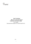
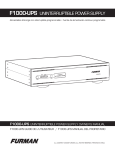
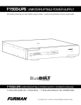
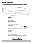
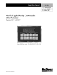
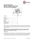
Service Bulletin
Title:
Bulletin #:
Models Affected:
Bulletin Revision:
Production Range:
ISA Turn-on Hangup
ISA0001
Issue Date: April 4, 2002
ISA 750, 800T, 450, & 500T
A
01/2000–04/2002 (serial # 0100xxxxx–0402xxxxx)
Description
The circuitry that controls protective current cutback in ISA amplifiers may in some instances cause a channel—usually
channel 1—to “hang up” at turn-on. This problem is most pronounced in the ISA 750 and ISA 800T models, but may also
occur in some ISA 450 and ISA 500T amplifiers.
Symptoms
When the amplifier is turned on, one or both channels remain inoperative, with their respective clip LEDs lit. In some cases,
the problem will clear by itself after several seconds. This problem is merely a nuisance and presents no danger to the
amplifier, the speakers, or the rest of the sound system.
Any one or more of these situations will tend to aggravate the problem:
•
High-pass filters (low-frequency) filters engaged
•
A DataPort accessory powered by the amp
•
Low AC line voltage
•
Cold ambient temperature
Passing an audio signal of a sufficient level through the affected channel will usually clear the problem; the level required
generally depends on the severity of the hang-up.
Background: the cause and the remedy
Each channel has an operational amplifier (op amp) driving its output stage. Its supply rails furnish just enough current for
normal operation by themselves and use the output signal to help replenish them. When the output stage tries to put out too
much current into a short circuit or abnormally low load impedance, it clips prematurely at a very low voltage; as a result,
there is not enough output signal to replenish the op amp supply rails. The starved supply rails collapse, and with them, so
does the op amp output. This is a normal and vital part of the amplifier’s protection against short circuits.
A channel hangs when the op amp rails and the bias in the output transistor circuitry do not settle to their correct values
quickly enough after turn-on. The op amp output swings to one rail, causing it to collapse and in turn causing the bias to not
settle correctly. As a result, there is no negative feedback to force the op amp to resolve itself to zero volts.
To correct the situation, replace the 5.6-volt zener diodes (D107, D110, D207, and D210) with 4.7-volt diodes and recalibrate
the current-limit trimpots (R139, R140, R239, and R240).
Temporary work-arounds
Until the amplifier can be serviced, one of these actions will usually clear its hang-up and get it working properly:
•
Quickly turning it off and on (CAUTION: this will cause an audible pop in any loudspeaker connected to the amp)
•
Unplugging and re-connecting speaker load from the channel output
Instructions
Tools and materials required:
•
•
•
•
•
Soldering iron with fine tip (recommended range 25 to 60 W)
Rosin-core solder (60/40 or 63/37 eutectic type)
Long-nose pliers
#1 and #2 Philips screwdrivers
Small diagonal cutters
ISA0001
1
Tools and materials required (continued):
• Desoldering equipment or solder braid
• Four 4.7-volt ¼-watt zener diodes (Microsemi DZ840731ET/R; QSC part number QD-0004.7-ZT)
Test equipment required:
•
•
•
•
•
•
•
•
Oscilloscope
2-ohm resistive load (rated for at least 1200 watts)
Wire or other means of shorting the amplifier output
Variable AC transformer (e.g., Variac, Powerstat, etc.) rated for 25A (120V) or 12A
(230V). Make sure your AC supply is appropriate for the amplifier.
1 kHz audio sine wave generator
Digital multimeter
AC current probe (e.g., BK Precision model CP-1)
Trimpot adjustment tool (non-conductive)
Note: The circuit boards in the ISA 750 and ISA 800T are double-sided, while those in
the ISA 450 and 500T are single-sided. Therefore, to minimize disassembly, this bulletin
recommends two different procedures among these models:
D107 & D210:
0.15–0.2"
3.8–5.1 mm
D207 & D110:
0.3"
7.6 mm
0.4"
10.2 mm
Figure 1. Prepare the leads of the
new zener diodes.
•
In the ISA 750 and ISA 800T, the zener diodes will be unsoldered and soldered from the component side. The instructions for this procedure begin below.
•
In the ISA 450 and ISA 500T, the new zener diodes will be soldered “piggyback”-style to the old ones. The instructions
for this procedure begin after those for the ISA 750 and ISA 800T.
Procedure: Replacing zener
diodes in an ISA 750 or ISA 800T
amplifier
1.
Disconnect the amplifier from AC and wait at least 10 minutes
for internal voltages to bleed down. Remove the top cover.
2.
Prepare the new zener diodes as shown in Figure 1.
3.
Remove the four screws on the bottom of the amplifier that
fasten the heat sink to the chassis.
4.
Remove the three screws that attach the channel module
assembly to the chassis standoffs.
5.
Lift up the front of the channel module assembly. Rotate it so
that channel 1’s module (the lower one) is on top; set the
assembly down in the chassis with the heat sink resting on
the standoffs (Figure 2).
6.
Disconnect the ribbon cable from the channel 1 module.
7.
Locate zener diode D107. It is near where three wires are
soldered to the circuit board and secured with hot glue. If the
hot glue covers the diode, use the tip of your hot soldering
iron and a small screwdriver to melt and clear the glue away
(Figure 3).
8.
Notice the orientation of D107. Unsolder and remove it; be
careful not to damage the through-plating in the holes. Install
and solder a new zener diode oriented in the same direction.
Do the same with zener diode D110.
9.
Reattach the ribbon cable and turn the channel module
assembly back over so that the channel 2 module is on top.
10. Locate zener diode D207 and notice its orientation. Carefully
2
Figure 2. Prop the channel module assembly up on the
chassis standoffs.
Figure 3. You might need to clear hot glue away from
diode D107. Use your hot soldering iron tip.
ISA0001
unsolder and remove it. Install and solder a new zener diode oriented in the
same direction. Do the same with diode D210.
11. Check your work. Don’t reattach the channel module assembly and heat sink to
the chassis yet. Instead, continue with the bias and current-limit calibration.
Procedure: Installing new zener diodes in an
ISA 450 or ISA 500T amplifier
New 4.7-volt zener
Old 5.6-volt zener
Figure 4. Solder a new zener diode
“piggyback”-style onto each old one.
1.
Disconnect the amplifier from AC and wait at least 10 minutes for internal voltages to bleed down. Remove the top cover.
2.
Remove the four screws on the bottom of the amplifier that fasten the heat sink to the chassis.
3.
Remove the three screws that attach the channel module assembly to the chassis standoffs.
4.
Locate zener diodes D107 and D110 on the channel 1 module (the upper circuit board). Bend and trim the leads of two
new zener diodes and solder them piggyback-style to D107 and D110, oriented in the same direction (Figure 4).
5.
Turn the channel module assembly over and repeat step 4 with zener diodes D207 and D210.
6.
Check your work. Don’t reattach the channel module assembly and heat sink to the chassis yet. Instead, continue with
the bias and current-limit calibration.
Procedure: Bias and current-limit calibration
Note: During the current-limiting part of this procedure, the amplifier will draw high amounts of AC: approximately 22 amperes at 120V, or 11 amperes at 230V. Be thorough, but work quickly to avoid tripping the amplifier's circuit breaker.
1.
Start with the variable transformer turned all the way down to zero, the amplifier turned off, and its top cover still removed.
2.
On the amplifier's circuit boards, locate resistors R147 and R247, and trimpots R131, R231, R139, R239, R140, and R240.
To reach R147 on the ISA 750 and ISA 800T or R247 on the ISA 450 and ISA 500T, rotate the chassis module assembly
and rest it on the heat sink so the bottom circuit board is accessible. Note that the trimpots for the bottom channel
module are located on a
small circuit board next to Table 1.
the top module.
3.
Plug the amplifier into the
variable transformer.
Calibrations
Adjust
4.
Turn the gain controls all
the way down.
Channel 1 bias: DC voltage across R147
5.
Turn the amplifier on and
gradually turn up the
variable transformer to
the amplifier's normal
operating voltage while
you monitor its AC current
draw (it should not
grossly exceed the idle
current figures in Table 1).
Make sure the amplifier is
functioning correctly.
ISA 450 &
ISA 500T
ISA 750 &
ISA 800T
R131
0.12 V
0.07 V
Channel 2 bias: DC voltage across R247
R231
0.12 V
0.07 V
Output current into shorted load
Channel 1: R139 & R140
Channel 2: R239 & R240
4–5 A
8.5–9 A
AC current when driving shorted load*
Channel 1: R139 & R140
Channel 2: R239 & R240
4.5–5.5 A
5.5–6.5 A
Clipping voltage into 2 ohms (RMS)
Channel 1: Adjust R139
for symmetry
Channel 2: Adjust R239
for symmetry
33.5–37.5 V
44–49 V
Clipping voltage into 2 ohms (peak)
Channel 1: Adjust R139
for symmetry
Channel 2: Adjust R239
for symmetry
47.4–53 V
62.2–69.3 V
0.4 A, ±10%
0.6 A, ±10%
Bias adjustment (perform
only with unit at ambient
temperature)
Note: This calibration must be
done with the amplifier
circuitry at ambient temperature. If the amp has begun to
warm up, you must turn it off
ISA0001
Idle AC demand* (at ambient temperature;
higher when hot)
*Figures shown are for 120V amplifiers; multiply current by 0.5 for 230V or by 1.2 for 100V.
3
and wait until it cools down to about room temperature.
6.
Measure the DC voltage across R147. Adjust bias trimpot R131 to reach the correct voltage shown in Table 1.
7.
Next, measure the DC voltage across R247. Adjust bias trimpot R231 to reach the correct voltage shown in Table 1.
8.
Turn off the amplifier and reattach the channel module assembly and heat sink to the chassis.
Current limit adjustment
Note: Read through these instructions before proceeding. To avoid tripping the amp’s circuit breaker, work carefully but
quickly, and don’t run the amp too long at full power into 2 ohms. If you don’t have the equipment to do this procedure
properly, it is better to skip it and leave the current-limit trimpots as is than to risk misadjusting them.
9.
Set the audio sine generator to 1 kHz at 1 volt RMS and connect it to channel 1's input. Connect channel 1's output to a
2-ohm load, and connect the oscilloscope probe across channel 1's output.
10. Turn the amplifier on. Turn up channel 1's gain control partway. On the oscilloscope you should see the amplitude of the
sine wave increase accordingly.
11. Turn the gain control back down and apply a short circuit across the output terminals of channel 1. Clamp a current
probe either onto one of the brown wires running to the AC switch or onto the gray output wire from channel 1's module.
12. Turn the gain control all the way up. Adjust trimpots R139 and R140 equally until the current measured falls within the
range shown in Table 1.
13. Turn the gain control all the way down and remove the short circuit so the channel drives the 2-ohm load. Turn the gain
control back up until the output clips. The voltage at which the signal starts to clip should fall within the range shown in
Table 1. If the clipping is asymmetrical, that is, the signal clips on either the positive or negative side first, adjust R139
to make it symmetrical.
14. Turn the gain control down. If the amp has begun to warm up, shut it off and let it cool a few minutes before proceeding
with channel 2.
15. Repeat steps 8 through 12 for channel 2. Use trimpots R239 and R240 to adjust the current limiting in steps 11 and 12.
16. Turn both channels’ gain controls all the way down. Clamp the current probe onto one of the brown AC wires to check
the amp’s idle current. If the amplifier is still at about room temperature, the idle current should match the value shown
in Table 1.
Finishing the repair
17. Turn the amplifier off and disconnect all input and output cables.
18. Re-install the top cover. The amplifier can be returned to use.
Contact information
If you need any further information regarding this service procedure, please contact QSC Technical Services at the addresses
or numbers below.
Telephone:
1-800-772-2834 (within USA only)
+1 (714) 957-7150
Fax:
+1 (714) 754-6173
E-mail:
[email protected]
Web site:
www.qscaudio.com (product info and support)
www.qscstore.com (on-line technical services and accessory sales)
Postal and parcel address:
QSC Audio Products, Inc.
Technical Services Group
1665 MacArthur Blvd.
Costa Mesa, CA 92626 USA
4
ISA0001