1
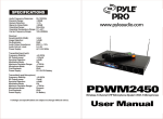
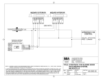
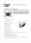
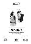
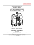
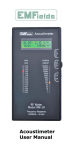
PDWM 2250 User Manual
19" Rack Mount Dual VHF wireless
Part name (Hand-held microphone)
Rechargeable Hand-Held Microphone System
Function
Front Panel
(1) (5)LCD:when power is on, it becomes green which can
show FREQ (receiving frequency of the device);OO-30 (rate
of sound volume).LineAl8 (channel Aor 8);
T
(radio fre-
(1 )headnet
(2)indicator
(3)power switch
(4 )power case
(5)8attery
(6)8attery cover
Operation
1.Please take the following working flow diagram for
quency indicator) which shows the level of the signal when
the microphone is on." »))) " (acoustical frequency level in-
reference on using this machine-connect the mix
dicator) it waves with the sound of microphone, from
out of receiver with mic input on the
Od8-35d8 to "iiiiiii"
(2) (6)press button(SET)to set the functions of the device;
for the volume, press the button, the code number(OO-32)
flashes on the LCD, push the "L,"or"\l"button to choose
amplifier.
2.Power 11 OV, switch the power, set the volume of
your sound equipment.
3 .Adjust the volume in right sound, make MIC1 and
MIC2 harmony, which will make you enjoying the
the suitable value of the sound, then push the button again,
and the value on the LCD stops flashing, setting is completed.
(3) (7)Volume control key"-"; to be used together with the set
button to decrease the sound, less value lower sound.
sound well.
4.Please plug out the power if you will not use the
machine long time.
(4) (8)Volume control key "+"; to be used together with the
set button to increase the sound, bigger value, lower sound .
(9)power button press this button, the electric power will be
on and the receiver stats to work and the display panel lights.
(1 O)lndicator of charging: put the rechargeable battery into
the battery case , the indicator is on, it will be dark after full
charging.
www.pyleaudio.com ~~LE®
Operation OfHand Held Transmitter
Rear Panel
1. First open the battery housing in anti-clockwise direction.
2.Conserve the battery inside on the + - palarity of battery.
3.Fit the battery compartment back in clock wise direction.
4.Pull the sliting switch of the grips to the first stage, to
the out correct signal is sent out, the white LED indicator
(1) (4)ATTN Port: install ATTN A. ATTN B
is light. pull second stage so as to be ready for transm(2)Mix out socket
itting speech.
(3)power: 11 OV/60Hz
5. Remove the sliding switch to the "off' side when it is not
(5)channel B Audio out
used.lf it is not used for a long time. Please take out
(6)channel AAudio out
the battery.
6.When filp the LED power switch of grip up. If one is light.
System connection flow diagram
the volume of battery is normal, if the LED indicator is
light all the time. If the LED. indicator is neither bright,
nor light, the battery is used up recharge the battery.
1 1-----'8-----'
RECIEVER
L
AMPLIFIER
Specifications
• Professional VHF 2 Channel Wireless System
• Dual Handheld Microphones Included
KAROKEAMPLIFIER
• Dual Telescoping Receiver Antennas
• Dual Volume Controls With Digital Readout
• Dual Charging System
• On/Off Broadcasting Switch
Installation ofreciever
• 1/4" Individual line outputs & Mixed 1/4" Outputs
• Carrier Frequency: 174MHz-216MHz
• Keep the machine 1m above the ground
• Dynamic Range: 100dB
• Keep the machine away 1m against the wall.
• Total Harmonic Distortion : 0.5%
• Pull the antenna up rightness fully
• Frequency Response: 40Hz-18KHz
• Make the transmitter point to the antenna without barrier
• Operation Range: 50-180 Meters
• Keep the reciever away any digital equipment(such as
• Signal to Noise Ratio: 105dB
CD,VCD,PC. or other radio equipment)
• Receiver Power Supply: AC 11 OV/240V
• Microphone Power Source: 8.4 Volt Rechargeable
• Receiver Dimensions: 1.8" X 18.9" X 1.3"
• Microphone Dimensions: 9.6" X 0.7" X 0.5"