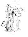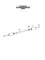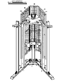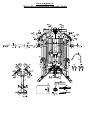
1
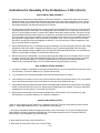
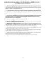
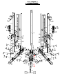
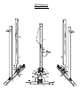
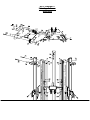
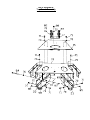
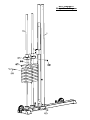
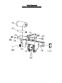
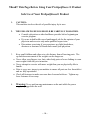
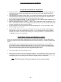
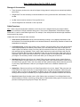
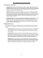
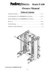
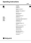
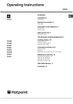
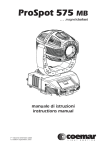
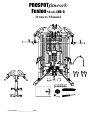
PROSPOTfitness®
Fusion Model HG-5
Owners Manual
Serial Number: ____________________HG5
HG-5
Owners Manual
Table of Contents
Assembly Instructions……………………..…………………………..……..2-17
Use and Operation of Your PROSPOTfitness® Product….………………..18-22
Periodic Maintenance of your PROSPOTfitness® Product……………….… 23
Parts List…………………………………………………….………………..24-25
Trouble Shooting……………………………………………………………..26-28
Warranty & Contact Information……………………………………….…….…29
Note this unit consists of six total boxes:
Three Boxes Labeled Box 1-3, HG-5 & 6 Base unit common parts
One Box Labeled Box 4, HG-5 Kit Conversion
Two Weight stack boxes labeled plates 20-100 lbs
-- 2 --
Instructions for Assembly of the ProSpotfitness® HG-5
•
Before assembly, choose a safe location for your PROSPOTfitness® HG-6. The PROSPOTfitness® HG-5
has a footprint of approximately 8’x 8’. The surface should be level and even. The barbell is approximately
7’ long. Locate your PROSPOTfitness® HG-5 away from any source of water. Do not allow any liquid to be
near the machine or spilled on any electrical part. Do not insert any object into the electrical box.
•
This unit uses standard 110-volt household current. Since there are two Power Adapters for this unit we
recommend using a Surge Protector Plug Strip to protect and extend the life of the power supplies and the
Electronic Box from power surges and lightening strikes. The Neon Lighting System does not have an on/off
switch. Lights come on when Power supply is plugged into plug strip. A Surge Suppressor Plug strip with a
switch will allow shutting Lights off when unit is not in use. A flashing green light will appear on the Electronic
Box when power is on. When sensors are activated, a steady red light will also come on.
•
The HG-5 unit is designed for climate controlled environments (indoor use only). Outdoor or non-climate
controlled use may affect the proper function of HG-6 and will void the warranty.
•
Assembly time is approximate 2 hours.
•
A flat area of 8’ x 8’ will be required to assemble and properly use the PROSPOTfitness® HG-5.
•
You will need the following tools and a helper to complete the assembly:
•
•
•
•
•
•
•
•
•
4 mm Allen Wrench
5 mm Allen Wrench
17 mm (11/16”) Hex Head Wrench
19 mm (3/4”) Hex Head Wrench
Adjustable wrench
Metric Socket Set
Philips Screw Driver
Pliers
Scissors and or Razor knife
•
Floor Padding, such as cardboard, to avoid scratching your floor during assembly.
•
Carefully remove parts from packaging. A good pair of scissors will be helpful in separating the parts from
one another while removing them from the cartons. Be careful not to cut or damage parts with scissors or
razor knife. Remove all parts from packing. Make sure there are no small parts left in boxes. Do not discard
boxes until assembly is complete.
•
Before assembly, separate and identify the right-sided parts from the left-sided parts. These parts are easily
distinguished by the manner in which the pre-drilled holes align with corresponding parts, or are identified by
“L“ & “R” stickers. Left and right are determined by facing the unit. Not the user’s perspective.
•
The PROSPOTfitness® HG-5 uses several different lengths of bolts. All fasteners come in labeled Blister
Packs by part number. Be careful to use the correct length of bolt called for at each step of assembly. Do not
remove fasteners from Blister packs until part is needed.
•
Note some parts mat come preassembled with fasteners.
•
HAND TIGHTEN all bolts. DO NOT fully tighten bolts until instructed to do so.
•
Assistance by a second person is recommended for some steps of this assembly.
•
WARNING: Never perform any maintenance on the ProSpotfitness®
HG-5 while the Power Supply is plugged into the wall !!!
ALWAYS REMEMBER: After the initial set up of the system or after performing any
service on the unit, RESET the Computer on your ProSpot system before using it. Just unplug
the power supply from the Electronic Box, wait 30 seconds and plug back in. Resetting the
Computer allows it to recalibrate and work to its greatest efficiency.
-- 3 --
Instructions for Assembly of the ProSpotfitness® HG-5
Step #1 MAIN FRAME ASSEMBLY
1. Referencing Diagrams 1 & 2, find the part Front Cross Brace (3). The Wire Harness (108) that runs thru this
part. This may be packed in this Cross Brace to prevent damage. Pull on ties and harnesses so that
connector ends hang loose out of access holes. Be careful not to pull too hard and remove or damage the
wire harnesses.
2. Now place the Rear Bottom Panel (5) in center of the assembly area. Next place the Right and Left Base
Rails (1, 2) opposite each other on each side of the Rear Bottom Panel. Note the 7/8” access holes for
wiring on side of Right and Left Base Rails (1, 2) should face inward. Now position the Front Plastic Bottom
Panel (4) (Remove paper cover on plastic) in front of the Rear Bottom Panel (5) between the Base Rails.
Insert Bolts (74) thru the Backing Plate (158) and attach the Side Rails (1 & 2) to the Rear Bottom Panel
using M12 x105 Bolts (74), M12 Washers (72) & M12 Nuts (73). Do not fully tighten bolts at this time.
3. Now place the Front Cross Brace (3) between rails so that the access holes with the harnesses hanging out
on the end of the Rear Cross Brace (3) align with the holes of the Base rails (1 & 2). Make sure the wire
harness that comes out of the middle of the Front Cross Brace (3) faces toward the back of the unit. Refer to
Diagrams 1 & 2.
4. Next feed the two Wire Harnesses (108) thru the access holes in the Right and Left Base Rails (1 & 2). Pull
up thru the round hole in the Right and Left Base Rails (1 & 2). Insert M12*105 Bolts (74) thru the Backing
Plate with Panel Hook (69) and attach the Side Rails (1 & 2) to the Front Cross Brace using M12 Washers
(72) & M12 Nuts (73). Do not fully tighten bolts at this time.
5. Now place the Right & Left Locking Posts on the Bottom Base Rails (1 &2) and secure with M10*20 Bolts
(71) and M10 Washers (70). Be careful not to crush wire harnesses at bottom of post. Then according to
Diagram 2 connect the two Wire Harnesses (108) to the Locking Post Wire Harnesses (107). Pull Barbell
Cables out of top of the Locking Posts and let Cable Knuckle and Barbell Cable hang towards the front of
the Locking Post for now.
6. According to Diagram 1 place these Upright Posts (6) and place on the Bottom Base rails (1 & 2) and secure
with M10 *20 Bolts (71) and M10 Washers (70).
7. Before installing the Rear Upright Support Post (9), install the Neon Light (104 using M3*10 Screws (105)
and M3 Washers (106) according to Diagram 2.
8. Now place the Rear Upright Support Post (9) on the Rear Bottom Panel (5) and secure with M12* 20 Bolt
(75) and M12 Washer (72).
Step #2 MAIN UPPER FRAME ASSEMBLY
1. According to Diagram 4 attach Lat Pulley Bracket (17) to the Rear Top Panel (16) using M10*25 Bolts (88)
and M10 Washers (70). Tighten Bolts Securely.
2. Now according to Diagram 3 attach the Rear Top Panel to the Rear Upright Support Post (9) using M12*20
Bolt (75) and M12 Washer (72).
3. Now according to Diagram 3 install the Front Top Panel (15) to the Locking Posts (11) & (12) using M12*100
Bolts (80), M12 Washers (72) and M12 Nuts (73). Make sure the Barbell Cables are positioned in front of the
Bolts (80) just installed.
4. Now according to Diagram 3 install two Upper Linking Plates (26) on each side Front Upright Support Post
(6) using M12*100 Bolts (80), M12 Washers (72) and M12 Nuts (73).
5. Next attach the two Upper Linking Plates (26) to the Front top Panel (15) using M10*20 Bolts (71) and M12
Washers (70).
6. Now according to Diagram 3 install the four Small Double Groove Pulleys (114) in the two Upper Linking
Plates (26) in the using M10*100 Bolts (84), M10 Washers (70) and M10 Nuts (82).
-- 4 --
Instructions for Assembly of the ProSpotfitness® HG-5 (con’t.)
Step #3 FINAL FRAME ASSEMBLY
1. Now according to Diagram 3 install the Middle Cross Brace (18) using M10*65 Bolts (100), M10 Washers
(70 and M10 Nuts (82).
2. Next find the Front Top Rail (27) and attach the Front Panel Tabs (49) to the back of the Rail using Pan
Head Bolts M4*10 (118) & M4 Washers. Make sure the Tabs are facing downward.
3. Now install the Front Top Rail (27) using M12 x 105 Bolts (74), M12 Washers (20) and M12 Nuts (73).
4. Now according to Diagram 1 attach the Cable Head assemblies (24) to each Front Upright Post (6) using
M12*70 Bolts, M12 Washers and M12 Nuts.
5. Installation of Weight Bar Cables (128 & 129): Uncoil the Cables coming out of the Locking Posts. Make
sure the Bar Cables are untwisted all the way down to the pulleys on the Locking Blocks (54, 55). Now feed
the Cables up and over the Small Double Groove Pulley (114). Then pull down the Rear Cable Knuckle and
attach to the Right and Left Base Rails (1, 2) using M12*100 Bolt (80), two Spacers (131), two M12 Washers
(72) and M12 Nuts (73) on each side. Make sure cables run outside the brace on the Locking Posts.
Reference Diagrams 7.
6. According to Diagrams 7 the rear cable knuckles part of the Weight Cables (128 & 129) when installed
should face towards the Locking Posts (7, 8). Now plug in the single plug of the Locking Post Wire Harness
(155) into the socket connection on the Rear Cable Knuckles on each side.
7. To finish the Weight Bar Cable installation take the Front Cable Knuckle that are hanging out of the top of
each post and flip the cables forward toward the front of the unit between the Linking Plates over the double pulley just
installed.
8. Reference Diagrams 3, 7 & 11. The next step is to install the Double Groove Pulleys (112) with Right & Left
Weight Bar Support Brackets (32 & 33) in each Upper Linking Plate assembly towards the front of the unit
using M10*105 Bolts (103), M10 Washers (70) and M10 Nuts (82). Make sure the Weight Bar Cables (128 &
129) are untwisted all the way down into the Locking Post to the pulleys on the Locking Blocks (54 & 55).
Then lay the cables toward the front of the unit between the Linking Plates over the Double Pulley (112) to
be installed.
9. Now install the two Cable Keeper M6*90 Bolts (109), M6 Washers (110), M6 Lock nuts (111) in the Upper
Linking Plate assemblies above the two rear Double Groove Pulleys (114). These bolts prevent the Weight
Bar Cables from jumping off the pulleys during workout.
9. Next according to Diagram # 1 & 2, place the Electronic Box (101) on the Bottom Panel (4) so that the lights
are facing up and power plug of the Box receptacle is facing toward the back of the unit. Plug in Cross Brace
wire Harness (108) to each of side Electronic Box (101). Now place the Electronic Box Cover (56) over the
Electronic Box (101) and attach with two M10*95 Bolts (157), four M10 Washers (70) and two M10 locknuts
(82).
10. Now its time to tighten all the bolts previously installed. Starting at the bottom of the unit working your way to
the top, tighten bolts securely but do not over tighten.
11. As shown in Diagram 2 feed the Power Supply Cord (102) thru the Rear Support Post into Electronic Box
(101). Next plug Power Adapter into Surge Protector Power Strip. Once it is plugged in the green light
should flash about once every second.
12. As shown in Diagram 2 feed the Neon power cord thru the Rear Support Post and connect to the Neon Light
wire harness. Then plug in the Neon Power Cord (155) into Neon Power supply (154). Next plug Neon
Power Cord (155) into a Surge Protector Power Strip. The Neon Light should turn on. If light does not turn
on, check wiring.
-- 5 --
Instructions for Assembly of the ProSpotfitness® HG-5 (Con’t.)
Step #4 WEIGHT BAR ASSEMBLY
1. Now its time to install Sensor Weight Bar (34). Reference Diagram 11. Using a 5mm allen wrench remove
the M8*40 Screw (121) Head Screw & End Cap (45) off each end. Now using a 4mm allen wrench, remove
the Spacer Collar (48) from each end of Sensor Weight Bar. Next remove the Rotating Loop (113) with the
steel spacer bushings. Set these parts aside for the moment.
2. This may take two people to perform this next task. Place Sensor Weight Bar in front of unit. Grab and touch
both at the same time the metal plate on the Weight Bar Cable Knuckles (128 & 129) that are on the front of
the unit. This will trigger the sensor to release the Cables to allow down ward movement. Pull down to waist
level and hold these at this position. Make sure Cables are not twisted and the metal face of Cable Knuckle
is facing inward. If you let go the Cables, they will retract back into unit. Now have your assistant slide end of
the (34) Sensor Weight Bar thru holes in knuckles on each side. Note: There is a key slot cut out in Cable
Knuckle for a metal pin on Sensor Weight Bar to slide thru. You can now let go of Sensor weight Bar. It will
not move unless Sensor is triggered.
3. Now reinstall Rotating Loop (113) with the steel spacer bushings. (The same way they came off.) Next install
the Spacer Collar (48) so that it is against the Rotating Loop (113) bushing and tighten with 4mm Allen
wrench. Now install the Olympic adapters (35), End Caps (45) and tighten M8*40 Screw (121) with M8 Lock
Washer (120) and M8 Flat Washer (119) with 5mm Allen wrench.
4. Now test movement of Weight Bar. Try lowering and raising the Weight Bar to the furthest points. If it sticks
or doesn’t work correctly, check the Weight Bar Cables over the pulleys to make sure they are not crossed
or twisted. According to Diagram 11 check for proper cable runs over pulleys and Cable Keepers are
installed, not over tightened. Make sure all wire harnesses are plugged together correctly.
Step #5 WEIGHT STACK ASSEMBLY
1.
As shown in Diagram 4 assemble the two Upper Pulley Brackets (14) to the Guide Rod Top Plate (53) using
M10*20 Bolts (71) and M10 Washers (70). Tighten bolts securely.
2.
To get started remove Weight Stack plates (65) and Top Plate (66) from its Cartons.
3.
Now working on one side of unit at a time, insert Guide Rod Cups (53) into Base Rails (1 & 2) if not already
done. Next insert the Weight Stack Guide Rods (10) into each of the Guide Rod Cups.
4.
Add Weight Plates (65) starting with the bottom #100 weight plate, slide down on Guide Rods. Keep Weight
Plates in order and facing to front of unit. Repeat until all weight plates are installed. This step is easier with
assistance from another person. Then install Top Plate (66).
5.
Next install the Guide Rod Top Plate onto the Guide Rods (10) and bolt to Top Front Panel (15) using
M10*20 Bolts (71) and M10 Washers (70). Reference Diagram 4.
Step #6 CABLE INSTALLATION
There are three separate sets of cables for the resistance exercises. There are three different points to adjust
cables. 1. Weight Stack Adjuster Bolt 2. Large Equalizer Pulley Bracket
1. According to Diagram 5
7 install the Weight stack Cable (133). Found in Box 4. It runs thru the Weight Stack
Pulley Bracket, around the Equalizer Pulley Bracket (135) and then attaches to the to Top Rear Panel with
M10*40 Bolts (76) M10 Washers (70) M10 Nuts (82).
2. Next install the Lat Cable (134) Found in Box 2.
3. Next install the Cross Over Cable (132). Found in Box 4
-- 6 --
Instructions for Assembly of the ProSpotfitness® HG-5 (Con’t.)
Step #6 MESH COVERS & ACCESSORIES
1. Referencing Diagrams (1 & 12) first attach the Side Mesh Cover Frames (28 & 29) one side at a time.
Set Side Frame on the hooks near the base of the unit. One hook is part (69) and the other hook is on the
Rear Bottom Panel (5). Then attach the front top corner of the Side Frame (28 & 29) to the Front Top Panel
with M4*16) Screws (116) and M4 Washers (117).
2. To install the Rear Cover Frame (30) you need to temporarily unplug the power cords and then re-feed
these power cords thru the grommet hole in the Rear frame after it is installed. To install the Rear Mesh
Cover Frame (30) to the back of the unit align the pins of the two Side Frames with the holes in Rear Frame
and slide down onto the pins of the Rear Bottom Panel (5). These sometimes are a tight fit because of paint
build up on pins and holes.
3. Next find the correct Mesh Cover (150 Left side & 151 Right side) for installation. Starting at the front of
the unit stick the Velcro Cover in place and wrap around the back keeping the cover tight. Do not over
stretch Mesh material, this will cause wrinkles.
4. As shown in Diagram 10 install the Front Plastic Panel (152).
5. As shown in Diagram 7, drop in Angled Front Panel (130) between the Upper Linking Plate assemblies
onto the Front Top Panel and rest it on the Panel Tabs.
6. Weight Storage and Accessory Stand: As shown in Diagram 12 attach the Bottom Rails (40) to the
Weight Stand Main Frame (39) using M12*75 Bolts M12 Washers (72) and M12 Nuts. Make sure the curved
holders on the Bottom Rails (40) are facing inward toward each other. Tighten bolts securely.
7. Next Assemble the VKR Arm Pads (43 right & 44 left) to the respective VKR Frames (41 right & 42 left)
using M8 x 60 Bolts (124), M8 Washers (119). Tighten bolts securely.
8. Next Install the VKR vertical Handles (101) on to the VKR Frames (41 & 42) using M10 x25 Bolts (88)
and M10 Washers (119) Note there two positions for these handles.
9. Rubber Bumper Pad (94) goes on Storage Posts before any weights are put on it. Lat Leg Hold Down
Bar (21) stores vertically in center hole of Weight Storage Accessory stand.
10. Using the Foot Pump (87) inflate Stability Ball (85) to required firmness. Do not over inflate.
-- 7 --
HG-5 Diagram 1
Main Frame Assembly
158
HG-5 Diagram 2
Wiring Assembly
HG-5 Diagram 3:
Main Upper Frame
Assembly
HG-5 Diagram 4:
Top Panel Assembly
HG-5 Diagram 5:
Weight Stack Diagram
HG-5 Diagram 6:
Middle Cross Brace Assembly
HG-5 Diagram 7:
Cable Run Assembly Detail
HG-5 Diagram 8:
Lat Leg Hold Down Assembly
Diagram
62
HG-5 Diagram 9:
Mesh Panel Frame Assembly
HG-5 Diagram 10:
Weight Bar & Accessories Assembly Detail
!!Read!! This Page Before Using Your ProSpotfitness ® Product
Safe Use of Your ProSpotfitness® Product
1.
CAUTION:
This machine involves the risk of possible injury by its user.
2.
THE FOLLOWING RULES SHOULD BE CARFULLY FOLLOWED:
• Consult a physician or other healthcare provider before beginning an
exercise program.
• If you are in bad health or are handicapped, ask for the opinion of your
physician and exercise only under qualified supervision.
• Discontinue exercising if you experience any light-headedness,
dizziness or shortness of breath and consult your physician.
3.
Keep small children and others at a safe distance from all moving parts. The
up and down movement of the weights can be dangerous.
Never allow your fingers, toes, hair, other body parts or loose clothing to come
near weights while they are in motion.
Never attempt to exercise with more weight than you are physically able to
handle.
Prior to every use, inspect your machine to ensure all parts are free from defect
and are fully operational.
Check all fasteners to make sure none have loosened with use. Tighten any
loose fasteners if necessary.
•
•
•
•
4.
Warning: Never perform any maintenance on the unit while the power
supply is plugged into the wall.
-- 18 --
User Instructions for the HG-5
Touch Sensor Barbell Operation
1. Rotate the barbell so that the Touch Sensor Strip embedded in the barbell is touching your fingertips. It
is necessary for your fingertips to maintain skin contact with the Touch Sensor Strip throughout your
free-weight exercise.
2. Grasp the barbell using what is called a ‘false’ grip in which the thumb does not wrap around the bar but
rests alongside the index fingers. Using this type of grip will prevent your thumb from maintaining skin
contact with the Touch Sensor Strip when you attempt to lock the bar in place.
3. Once you have grasped the barbell, you will hear a soft ‘click’ and a solid red light will appear on the
Electronic Box in addition to the flashing green power light.
4. While still grasping the barbell, lift about 1”, using an even upward lifting motion on both sides of the
barbell. This upward movement will disengage the locking mechanism. If you have performed this step
correctly, the barbell will now be under your control.
5. Always remember to secure all weight plates with supplied spring clips. You are now ready to begin
your free-weight exercise routine.
6. Always maintain control of the movement of the barbell. Do not allow the barbell to swing against the
machine frame, as this may cause damage to the finish. Do not attempt to throw or slam the barbell
attached to the cables, as this may result in damage to the locking mechanism. Intentional misuse of
the HG-6 will void any and all warranties.
Spot Block Plates and Barbell Loading
Always use Spot Block Plates when using barbell as a secondary locking backup. The Spot Block Plates
can also be used as a training aid by limiting barbell movement when exercising. To position the Spot Block
Plates:
1. Place the barbell into the lowest position for the exercise you will be performing. To move the Spot
Blocks Plates, remove by grabbing handles and lifting up. You will see the top hook and stop pin that
goes in the holes. Place the Spot Blocks Plates above exposed tip of locking pin on rear support posts.
This will now restrict the movement of Sensor Weight Bar beyond this point.
2. The starting weight of the Sensor Barbell is 30 lbs.
3. Make certain the barbell is level before loading weight plates. Level the barbell by raising up one end of
the barbell until it is level. Load weights evenly on both sides of the barbell. Always use the Spring Clips
to hold plates tight. For heavy lifting, an after market Locking Bar Collar is recommended.
Note: The HG-5 unit has a 750-pound capacity. Do not exceed capacity!
-- 19 --
User Instructions for the HG-5 (cont’)
Storage of Accessories:
•
There Accessory hooks on the side of the Upper Linking plates for storing the two sets stirrup handles,
Nylon Rope.
•
Weight Plate Tree with accessory hooks and holders for Lat Leg hold down Bar, VKR handles, T-bar, &
Lat Bar
•
Lat Bar can be stored on hooks on Front top Rail of unit.
•
Sensor Weight Bar can be stored on Chin-Up hooks.
Cable Exercises:
Note: When using the weight stack resistance on the HG-6 unit, the weight shown by the weight indicator
numbers is not amount of weight resistance being used. There are two independent, 200-lb selector weight
stacks with 2:1 ratio for extra cable length travel. For example, if set at 60 pounds the actual weight resistance
for that stack is 30 pounds.
Listed below are a few sample Cable exercises:
•
Cable Cross Over Exercise can be performed standing or sitting on an a slightly inclined bench. Set
each selector Pin on each Weight Stack to the desired resistance. Attach Stirrup handles to Cable Head
Assemblies for hand grips.
•
Lat Pull Exercises: Connect the Lat Bar to the Lat cables. Set each selector Pin on each Weight Stack
to the desired resistance. Set Bench to flat position. Sit on the back pad of the bench so that you are
under Lat Bar. Pull Lat Bar to chest. For heavy Lat Pull exercises use the Lat Leg Down Bar. Insert the
Left and Right Lat Leg Adjustable Tube in each Cable Head receiver and lock into place with Pop Pin.
Place Lat Leg Down Bar in notches on Adjustable Tubes. Get in exercise position. Now adjust Lat Leg
Adjustable Tube in each Cable Head receiver up or down so pads on Lat Leg Down Bar are resting on
your thighs. This will hold you down on the bench while you are doing the Lat exercise.
•
Standing Curl: Remove bench from unit. Attach T-Bar to the two extension chains. Attach Chains to
Low Pulley Cables. Set each selector Pin on each Weight Stack to the desired resistance. While facing
the machine pull, grip the T-Bar in the Curl position and pull upward keeping elbows stationary and next
to your body. Adjust Extension Chains for your height so that there is consistent resistance thru
exercise.
•
Sitting Row: Remove bench from unit. Place Prospot Mat in front of unit. Attach T-Bar to the two Low
Pulley Cables. Set each selector Pin on each Weight Stack to the desired resistance. While facing the
machine, place your feet on the adjustable Foot Board, grip the T-Bar and pull backward and perform
Rowing Exercise. Adjust Foot Board for your height so that there is consistent resistance thru exercise
•
Rope Pull: Attach Rope Handles to the Lat Pull Cables. Now set selector Pin on Weight Stack to the
desired resistance. Perform exercise by pulling down on Rope handles. Many types of exercises can be
performed working muscle groups as Triceps, Abs, back etc.
-- 20 --
User Instructions for the HG-5 (cont’)
VKR & Dip Station Exercises:
•
VKR Exercise Place right & left VKR Attachments in receivers on Cable Head Assemblies. Attach
Padded Back Rollers in Cross Frame in center position and lock with Pin. With your lower back against
the Back Pad Roller Place elbows on the VKR Arm Pads, grab vertical handles and perform exercise by
lifting legs or knees up. Re-adjust VKR Frames up or down using the Pop Pin on the Cable Head
Assemblies if necessary for your height and comfort.
•
Dip Station Exercises: Place right & left VKR Attachments in receivers on Cable Head Assemblies.
Facing the machine grab horizontal handles and perform the Dip Exercise. For assistance doing this
exercise, attach the Dip Assist Belt to the Cable Head Assemblies connection. Set each selector Pin on
each Weight Stack to the amount of assistance needed to perform Dip Exercise. Once again facing the
machine grab horizontal handles, place knees on belt and lower body and perform Dip exercise.
Caution: Be careful not to fall off.
•
Performing Chin-Ups: Chin-Ups can be performed using the barbell when it is placed onto the notched
grooves on top of the HG-5. Ensure that the barbell is secure before performing chin-ups. For
assistance doing this exercise, attach the Dip Assist Belt to the Cable Head Assemblies connection.
Set each selector Pin on each Weight Stack to the amount of assistance needed to perform Chin-Up
Exercise. Facing the machine grab the Weight Bar, place knees on belt and lower body and perform
exercise. Caution: Be careful not to fall off.
Stability Ball Exercises:
This unit has been provided with a 24” Stability Ball and 39” x 70” Exercise Mat to perform exercises that
that work the “Core” muscle groups in your body and other specialize floor work. Here are a few sample
exercises:
•
Flat Bench Exercise: Remove bench from unit. Place Prospot Mat in front of unit. The Stability Ball
can be substituted for the bench during Flat Bench exercises. This increases the difficulty of the
exercise because it works more of the Core and stabilizer muscles. Start with lower weights and
work your way up.
•
Push-Up Exercise: Remove bench from unit. Place Prospot Mat in front of unit. Lower Sensor
Weight Bar to approximately one foot from the floor. With your feet on Stability Ball, perform push up
by placing hands on the Sensor Weight Bar and pushing up. Be care full not to fall down. Note this
type of exercise increases the difficulty because it works more of the Core and stabilizer muscles.
Adjust Sensor Weight Bar to other heights to ease or lessen the difficultly of this exercise.
•
Pull-Up Exercise: Remove bench from unit. Place Prospot Mat in front of unit. Lower Sensor
Weight Bar to approximately two feet from the floor. With your feet on Stability Ball, perform pull-up
by placing hands on the Sensor Weight Bar and pulling up. Be care full not to fall down. Note this
type of exercise increases the difficulty because it works more of the Core and stabilizer muscles.
Adjust Sensor Weight Bar to other heights to ease or lessen the difficultly of this exercise.
-- 21 --
User Instructions for the HG-5 (cont’)
Using optional FS-150 Bench:
• Leg Extension:
1. Set Selector Pin on each Weight Stack to 10lbs.
2. Adjust Foot Board to the second hole by pulling on Pop Pin Knob.
3. Then attach the long Bench Cables to the low-pulley connection using two cable clips on each. Make
sure the cable is taut by pulling out the bench until there is no slack in the cable.
4. Now set each Selector Pin on each Weight Stack to the desired resistance.
5. Next Position Bench Back Pad in the incline position close to 90 degrees.
6. Tilt Seat Pad to first incline position. Adjust Leg Support Rollers to Seat Pad Height.
7. Adjust Leg Rollers on Leg Developer by pulling on Pop Pin and position the Roller close to your ankle.
8. Grab Handles on Bench Seat while performing the Leg Extension exercise.
•
Leg Curl:
1. Set Selector Pin on each Weight Stack to 10lbs.
2. Adjust Foot Board to the second hole by pulling on Pop Pin Knob.
3. Then attach the long Bench Cables to the low-pulley connection using two cable clips on each. Make
sure the cable is taut by pulling out the bench until there is no slack in the cable.
4. Now set each Selector Pin on each Weight Stack to the desired resistance.
5. Slide Bench Slider Frame toward Leg developer and lock into place with knob on side.
6. Next Position Bench Back Pad in the flat position.
7. Tilt Seat Pad to first incline position. Adjust Leg Support Rollers to Seat Pad Height.
8. Adjust Leg Rollers on Leg Developer by pulling on Pop Pin and position the Roller close to your
ankle.
9. Next adjust each Leg Developer into the Leg Curl position by pulling the Pop Pin on the adjuster Plate
and lock into one of the top two holes.
10.Lay flat on Bench, hook your legs under leg rollers and grab handles on Bench Bottom Rail while
performing the Leg Curl exercise.
11.Re-adjust any or all of the previous adjustments to your height and comfort.
•
Leg Press:
1.
2.
3.
4.
5.
Adjust Foot Board all the way in by pulling on Pop Pin Knob and sliding in.
Place the Foot Plates in the in receptacles on Cable Head Assemblies.
Slide Bench all the way in. Set Bench Back Pad in flat position. Set Seat Pad in vertical position.
Pull and turn knob on side of Bench Slider Frame so that it is free moving. Slide toward unit.
Then attach the Short Cables to the low-pulley connection using two cable clips on each. Make sure
the cable is taut by pulling out the bench until there is no slack in the cable.
6. Now set each Selector Pin on each Weight Stack to the desired resistance.
7. Sit on Bench Back Pad facing unit and place feet on Foot Plates on Cross Brace and grab handles on
side of Bench Back Pad. Push out and place your feet on the secondary Foot Plates in the in
receptacles on Cable Head Assemblies.
8. Adjust the Foot Plates in the Cable Head Assemblies up or down for different angles of press and
comfort.
•
Rowing Exercise:
1. Use set up from Leg Press exercise.
2. Attach Stirrup Handles to pulleys on Middle Cross Brace.
3. Sit on Bench Back Pad facing unit and place feet on Foot Plates on Cross Brace and grab
handles on Middle Cross Brace. Push out and place your feet on the secondary Foot Plates in
the in receptacles on Cable Head Assemblies.
4. Grip the Handles and pull backward and push with your legs.
-- 22 --
Maintenance Program
The HG-5 is made of durable materials and has been factory tested to assure proper function and reliability. It is
designed in a way to allow easy replacement of parts both mechanical and electrical if the need should ever
arise. If you are a new owner of an HG-5 system, three important things need to be done to assure prompt
service under the warranty:
1. Fill out and fax or mail to us your Product Warranty Registration Card along with a copy of
your sales receipt (proof of purchase).
2. Your system needs to be set up properly according to the assembly manual.
3. Follow user instructions on how to properly use the system.
Note:
The HG-5 is recommended for climate-controlled environments. Outdoor use is not
recommended and will void the warranty.
Carefully inspect machine before each use to determine that it is free from defects.
Do NOT use the machine if you find:
1. A loose, broken or frayed power cord – (needs to be replaced)
2. Any broken, cracked, torn, frayed or defective part of the machine – (needs to be replaced)
3. Loose bolts or fasteners. Check all fasteners to make sure none have loosened with use.
Tighten any loose fasteners.
4. Pulleys sticking or Cables binding. Check for free movement of all cable and pulleys.
Adjust or replace if necessary.
Lubrication:
Lubricate the Internal Locking Blocks periodically by spraying a standard silicone lubricant (found in hardware
stores) into the top of the # 7 & 8 Locking Upright Posts in the inside corners of the tube. Do not over lubricate.
Warning: Never perform any maintenance on the unit while the power supply
is plugged into the wall.
-- 23 --
Prospot Fitness Fusion HG-5 Parts List
Part#
Description
QTY
Part#
47
48
49
50
51
52
53
54
55
56
57
58
59
60
61
62
63
64
65
66
67
68
69
70
71
72
73
74
75
76
77
78
79
80
81
82
83
84
85
86
87
88
1
2
3
4
5
6
7
8
9
10
11
12
13
14
15
16
17
18
19
20
21
22
23
24
25
26
27
28
29
30
31
32
33
34
35
36
37
38
39
40
41
42
Left Base Rail
Left VKR Frame
1
1
1
1
1
2
1
1
1
4
1
1
1
2
1
1
1
1
1
1
1
1
1
2
1
4
1
1
1
1
1
1
1
1
2
2
1
1
1
2
1
1
43
Right VKR Arm Pad
1
89
44
45
46
Left VKR Arm Pad
1
2
2
90
91
92
Right Base Rail
Front Cross Base Rail
Plastic Bottom Panel
Rear Bottom Panel
Front Upright Post
Left Locking Post
Right Locking Post
Rear upright Support post
Weight Stack Guide Rod
Left Leg Hold Down Adj Tube
Right Leg Hold Down Adj Tube
Footboard
Upper Pulley Bracket
Front Top Panel
Rear Top Panel
Lat Pulley Bracket
Middle Cross Brace
VKR Roller Bracket
VKR Roller Tube
Lat Leg Hold Bar
Left Foot Plate
Right Foot Plate
Cable Head assembly
Screw Down Pull Pin
Upper Linking Plate
Front Top Rail
Left side Mesh Cover Frame
Right Side Mesh Cover Frame
Rear Mesh Cover Frame
Front Cover Frame
Left Weight Bar Support Bracket
Right Weight Bar Support Bracket
Sensor Weight Bar
Barbell End Adapter
Spot Block Plate
Lat Bar (dual rotating)
Row Bar (dual rotating)
Weight Stand Main Frame
Weight Stand Bottom Rails
Right VKR Frame
Barbell end Cap
Barbell Spring Clip
Page 1
Description
QTY
Logo Plate
Foam Roller with cover
2
2
2
1
2
1
2
1
1
1
2
8
2
3
3
Roller Locking Pin
1
Barbell 50mm Rubber Bumper
Locking Barbell Spacer
Front Panel Tabs
Cup holder
Accessory Hook
Cup Holder Bracket
Guide Rod Top Plate
Left Locking Block
Right Locking Block
Electronic Box Cover
Screw Down Pull Pin
Weight Stack Guide Rod Cup
VKR Vertical Handle
Weight Stack Plates
Weight Stack Top Plate
Plastic Space Bushing
Weight Stack Pin
Backing Plate w/ Panel hook
Flat Washer M10
Hex Head Bolt M10*20
Flat Washer M12
Hex Nut M12
Hex Head Bolt M12*105
Hex Head Bolt M12*20
Hex Head Bolt M10*40
Large Single Pulley
Plastic Nylon Insert
Plastic Square End Cap
Hex Head Bolt M12*100
Hex Head Bolt M10*45
Hex Nut M10
Socket Head Bolt M10*45
Hex Head Bolt M10*100
Hex Head Bolt M8*20
Weight Stack Selector Rod 9 holes
Rear Single Groove Pulley
Hex Head Bolt M10*25
Pan Cross Self-Threaded Screw
ST2.9*12
Round Rubber End Cap
Small Single Groove Pulley
Wide Groove Pulley
-- 24 --
18
2
2
2
2
130
28
80
36
16
8
26
4
2
1
6
6
48
2
8
8
2
4
4
6
2
20
2
Prospot Fitness Fusion HG-5 Parts List
Description
Part#
93
94
95
96
97
98
99
100
101
102
103
104
105
106
107
108
109
110
111
112
113
114
115
116
117
118
119
120
121
122
123
124
125
126
127
128
129
130
131
132
133
134
135
136
137
Medium Single Groove Pulley
Rubber 48mm Bumper
Hex Head Bolt M12*85
Square End Cap
Hex Head Bolt M12*70
Foot Caps
Hex Nut M5
Hex Head Bolt M10*65
Electronic Box
Electronic Box Power Supply
Hex Head Bolt M10*105
Neon Light
Pan Cross Head Bolt M3*10
Flat Washer M3
Locking Post Wire Harness
Cross Brace Wire Harness
Hex Head Bolt with Sleeve
M6*90
Flat Washer M6
Hex Nut M6
Dbl Groove Pulley
Weight Bar Rotating Loop
Small Dbl Groove Pulley
Pan Cross Head Bolt M4*16
Flat Washer M4
Pan Cross Head Bolt M4*10
Flat Washer M8
Spring Washer 8mm
Pan Cross Head Bolt M8*40
Socket Head Cap M5*20
Hex Head Bolt M12*75
Hex Head Bolt M8*60
Hex Head Bolt M6*10
Pan Cross Head Bolt M6*10
Snap Clip
Left Weight Bar Cable Assembly
Right Weight Bar Cable Assembly
Angled Plastic Panel
Spacer Bushings
Cross over Cable
Weight Stack Cable
Lat Cable
Small Equalizer Pulley Bracket
LG Adj. Equalizer Pulley Bracket
Magnet Washer
QTY
Page 2
Description
Part#
10
3
2
4
4
4
8
4
1
1
2
1
2
2
2
2
138
139
140
141
142
143
144
145
146
147
148
149
150
151
152
153
4
154
14
4
2
2
4
155
156
157
158
Locking Block DBL Pulley Pin
Prospot Letters (set)
Extension Chain
Work Out Floor Mat
65cm Stability Ball
Foot Pump
Dip Assist Belt
Back Belt
Short Stirrup Handle
Long Stirrup Handle
Rope Pull
Left Side Mesh Cover
Right Side Mesh Cover
Front Plastic Panel
Plastic End Cap
Neon Power Supply
Power Cord
Hex Head Bolt M10*95
Connection Plate
4
6
2
6
2
2
8
4
4
4
2
6
1
1
1
4
2
2
2
2
2
2
-- 25 --
QTY
2
1
2
1
1
1
1
1
2
2
1
1
1
1
6
1
1
2
2
Trouble-Shooting
How the Patented ProSpot System works:
Starting from the Computer Brain, a signal is sent from the left & right side, thru the L & R Grey Base Frame
Wire Harness (white lead), Locking Post wire harness to the Lower rear Cable Knuckle connector, to inside
Barbell Cable to the Sensor on the Barbell. When skin contacts is made with Barbell Sensors, the signals return
to the Computer Brain, at which a 12-volt charge is sent via the Base Frame Wire Harness to the contact strips
in the Locking Post to the solenoids, to release the spring loaded Slider Block Locking Pins when the Barbell is
lifted, allowing the Barbell to move up and down. When skin contact with Barbell Sensor is broken by either
hand, the Computer Brain reads this and stops the 12-volt charge to the solenoids, at which time, the spring
loaded Locking Pins instantaneously engages the hole on the Guide Post and locks the Barbell from any
downward movement.
Trouble Shooting of ProSpot Systems
ALWAYS REMEMBER: After performing any service on the unit RESET the Computer on your ProSpot system
before using it. Just unplug the power supply Electronic Box, wait 30 seconds and plug back in. Resetting the
Computer allows it to recalibrate and work to its greatest efficiency.
Electrical Service Inspection Checklist:
1. Check for proper functioning of wall receptacle. (Test plug for power)
a. If bad, find new 110V AC power supply.
b. Check surge suppressor plug strip for proper function.
2. Check wall transformer connection to Electronic Box. Should not be bent or loose.
a. If bad, replace Electronic Box.
3. Check for green flashing light, the indication power to Electronic Box.
a. If no green light, test 12V Wall Adapter for 12-17 volts output. If voltage is less or none, replace
12Vpower supply.
4. Inspect white connectors from Base Frame Wire Harness connection on Electronic Box for loose wires.
a. If loose, plug in tight.
b. If broken, replace Base Frame Wire Harness.
5. Inspect Base Frame Wire Harness for possible pinching in frame during assembly.
a. Replace Base Frame Wire Harness if damaged or defective.
6. Inspect Base Frame Wire Harness connection to Locking Post Wire harness.
a. If loose, plug in tight.
b. If broken, replace Base Frame Wire Harness or Locking Post Wire Harness.
7. Inspect Locking Post Wire Harness connection to Contact Strips.
a. If loose, plug in tight.
b. If broken, replace Locking Post Wire Harness.
a. Inspect Locking Post Wire Harness plug in connector to Lower Cable Knuckle.
b. If loose, plug in tight.
c. If broken, replace Locking Post Wire harness.
8. Check contact points of Sensor Weight Bar (Reference Diagram on page 28).
a. Check Sensor Collar for proper adjustment. Sensor Collar Brass Pin must make contact with
metal plate on Cable Knuckle.
b. Check Brass Contact Pin and Spring for proper continuity.
c. Check Spacer Collar for proper positioning.
-- 26 --
Trouble-Shooting (con’t)
Before performing the trouble shooting on this page, go thru the Electrical Service Inspection on the previous
page.
Symptom:
Solution:
Sensor Weight Bar locks prematurely during work out.
1. Perform Adjustments on Weight Bar / Cable-Knuckle assembly. See Diagram page 28.
2. Check Wire Harness for defective wire. (Continuity test)
Symptom:
Solution:
Sensor Weight Bar will not unlock at all.
1. Remove covers on both sides to gain access to Locking Post Wire Harness.
2. Unplug Sensor plugs from Rear Cable Knuckle and hold one in each hand at the same time.
3. If sensor triggers (red light comes on) then Wire Harness is good.
a. Recheck connections on Weight Bar / Cable-Knuckle Assembly. Make adjustments.
4. If sensor fails to trigger (no red light) then:
a. Re-check both Wire Harness’s with Meter (Continuity test) for defective wire and
replace.
Symptom:
Solution:
One side of system will not unlock.
1. Check Double Cable Pulleys for free movement.
2. Check connections from Locking Post Wire Harness to contact strips.
3. Check free movement of Locking Pin. (Manually pull down Pin)
4. Realign Contacts Pins to stay on track on Contact Strips. Adjust Bracket that holds the Pins
on bottom of Locking Block by loosing the screws and slide Bracket Plate in or out. Then
tighten screws. You may have to hold Bracket in place while tightening screws. Most of
time this Bracket will need to be adjusted go inward.
5. Trigger Sensor and test for 10-12 volts at Solenoid connection.
a. If it reads10-12 volts then replace Solenoid.
b. If no voltage, then check Wire Harness for defective wire. (Continuity test)
c. If Wire Harness is good the replace Electronic Box.
Symptom:
Solution:
Sensor Rod on Weight bar keeps popping up.
1. Remove Sensor Collar and Sensor Rod.
2. Straighten any bends. (If too bent up, replace.)
3. Before reinstalling, bend angle in Sensor Rod slightly downward, so that there is tension on
Sensor Rod to seat it.
Symptom:
Solution:
If all Neon Lights fail to turn on.
1. Check surge suppressor plug strip for proper function and 11ov output.
2. Test 12V Wall Adapter for 12-17 volts output.
3. Check Neon Light Wire Harnesses for possible broken wires or loose connections.
Symptom:
Solution:
If one of the Neon Lights fail to turn on.
1. Check Neon Light Wire Harness for that Neon Light possible broken wires or loose
connections. Repair or replace if necessary.
2.
Check for 12-17 volts output from where light plugs into Wire Harness.
a. If there is proper power then replace Neon Light.
b. If there is no power at connection then repair or replace bad wire harness.
For more detailed information go to our web site www.prospotfitness.net under the technical
section and go to the Service Manual for the Fusion Series.
-- 27 --
Warranty & Contact Information
Each PROSPOTfitness® Product comes with a limited parts replacement warranty. Please refer to the
actual warranty card included with your system for specific coverage.
Remember: To activate your Warranty, fill out and fax or mail to us your Product Warranty
Registration Card along with a copy of your sales receipt (proof of purchase) if your dealer has not
done this at time of purchase.
If you have any questions about performance under this limited warranty, please write us at:
PROSPOTfitness, Inc.
Attn: Warranty Service
2000 Newpoint Pl Pkwy. Suite 500
Lawrenceville, GA 30043
Office (770) 446-9299
Fax (770)-446-7213
Contacting ProSpot Fitness Technical Support:
Our Service Department can be reached M-F 9-5 pm EST.
Or e-mail us: [email protected]
If ordering replacement parts, please refer to the Owners Manual for part numbers and description.
Note: Owners Manuals & Warranty Registration cards can be down loaded from our web site.
For more information please refer to our Website at: www.prospotfitness.net
-- 29 --