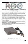
1
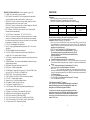
TABLE OF CONTENTS OWNER’S MANUAL 1. Readme First .................................................................................................................... 2 2. FCC Statement ................................................................................................................3 3. Safety Instructions ....................................................................................................4 - 5 4. Installation (Refer to REARconnectors on page 13) ................................................6 Television .......................................................................................................................6 Video Recorder ..............................................................................................................6 DVD Player ...................................................................................................................7 Multimedia/HDTV/XGA Monitor/Receiver Computer .......................................................................................................................7 Hi gh Definition Receiver .........................................................................................7 DM-5948S(T)(C) DM-6952S(T)(C) DM-7752S(T)(C) Remote Control Operation .......................................................................................... 8 5. Functions ................................................................................................................9 – 10 6. Parental Controls ..................................................................................................11 – 12 7. Rear Connectors .......................................................................................................... 13 8. Energy Saving .............................................................................................................14 9. Simple Troubleshooting..............................................................................................14 10. Specifications ................................................................................................................15 DM -5948S Specifications ...........................................................................................15 DM -6952S Specifications .......................................................................................... 16 DM -7752S Specifications ...........................................................................................17 Monivision Graphic Systems 11100 DANA CIRCLE . CYPRESS,CA 90630 All registered trademarks are the property of their respective owners 11. VGA Connector Assignment .................................................................................... 18 12. Appendix A : OSD Function......................................................................................19 13. Appendix B : Factory Preset Mode .......................................................................... 20 14. Appendix C : Remote Controller .............................................................................21 15. Appendix C (Cont’d) : Remote Controller Functional Matrix.............................22 16. Appendix D : VGA2 In & Panel Keys .................................................................... 23 17. T-Series Warranty........................................................................................................24 1 README FIRST FCC STATEMENT Thank you for purchasing the Princeton T series monitor. These easy start-up tips will guide you in making the connections to get you up and running. This equipment has been tested and found to comply within regulations for a Class B digital device, pursuant to Part 15 of the FCC rules. These regulations are designed to provide protection against harmful interference in a residential installation. This equipment can generate, use and radiate radio frequency energy and if not installed and/or used in accordance with the instructions provided, may cause harmful interference to radio communications. However, there is no guarantee that interference will not occur in a particular installation. If this equipment does cause harmful interference to radio or television reception, which can be determined by turning the equipment off and on, the user is encouraged to try to correct the interference by one or more of the following measures: Reorient or relocate the receiving antenna. l Increase the separation between the equipment and receiver. l l Connect the equipment into an outlet on a circuit different from that to which the receiver is connected. Consult the dealer or an experienced radio/TV technician for assistance. l USING W ITH A DESKTOP PC or LAPTOP: 1. Prior to connecting the T monitor, if you have a desktop monitor connected to your PC, please ensure that the video card refresh rate is set within the T frequency range by going to: Start…Settings…Control Panel…Display…Settings…Advanced…Adapter. Set the Adapter refresh rate to 60Hz or “Adapter Default”. See Appendix B, page 20 for details on resolution/refresh rates. This applies to the three supported resolutions of 640×480, 800×600 and 1024×768. Otherwise, the monitor will not display and the unit will go into standby mode (Yellow -orange LED). 2 Plug the power cord into the AC input on the rear of the T monitor, then plug the power cord into a 3-prong grounded outlet. 3. Connect the VGA cable provided from your computer’s VGA output to the input on the Monitor. VGA 1 is the VGA input port located in the rear of the monitor. VGA 2 is the VGA input port located in front of the monitor. Be sure the PC is powered on before the monitor. Press the V GA1/VGA2 select button, located next to the front VGA connector and on the Remote Control until the computer image is displayed. Warning: Only use shielded cable to connect I/O devices to this equipment. Changes or modifications not expressly approved by the party responsible for compliance could void your authority to operate this equipment. SIMULTANEOUS VIEWING OF THE MONITOR AND STANDARD PC MONITORS: 1. Connect the VGA cable from the PC’s VGA output to the VGA input.Then plug the desktop monitor’s VGA cable to the monitor VGA output. USING WITH A LAPTOP: If you are using Notebook: Press Fn + F5 (or Fn+F3) to output the display to CRT only ( CRT output combination key may be different on some notebooks), or press combination key again to show on both CRT and LCD display. USING WITH A MAC: 1. 2. 3. Plug the AC power cord from the power source (outlet) to the AC input of our monitor. Connect the MAC adapter to the MAC monitor output (if required by the MAC model). Refer to the adapter user’s manual for the proper dip switch settings. The optimum setting for the monitor is a resolution setting of 800 x 600 and a refresh rate of 75Hz. Make sure the display settings of the MAC is set to 800 x 600 at 75Hz as well.Note: You need a MAC adapter when using the monitor with older MAC Computers. The MAC adapter converts the output to VGA HD-15 pin out. This adapter is available at an additional cost from your authorized Princeton dealer. Connect the VGA cable from the monitor to ht e MAC adapter. USING WITH A VIDEO SOURCE or Cable TV ( DVD Player / VCR / LD Player ): Pling refer to the T Use’s Manual 2 3 Safety Instructions 1. Read all of these instructions. 2. Save these instructions for later use. 3. Follow all warnings and instructions marked on the product. 4. Unplug this product from the wall outlet before cleaning. Do not use liquid cleaners or aerosol cleaners. Use a damp cloth for cleaning. 5. Do not use this product near water. 6. Do not place this product on an unsuitable cart, stand or table; the product may fall causing damage or injury. 7. Slots and openings in the cabinet and the back or bottom are provided for ventilation. To ensure reliable operation of the product and to protect it from overheating, these openings must not be blocked or covered. The openings should never be blocked by placing the product on a bed, sofa, rug, or other similar surface. This product should never be placed near or over a radiator or heat register. This product should not be placed in a built-in installation unless proper ventilation is provided. 8. This product should be operated from the type of power source indicated on the marking label. If you are not sure of the type of power available, consult your dealer or local Power Company. 9. This equipment is to be electrically grounded. This product is equipped with a three-wire plug with a third (grounding) pin. This plug will only fit into a grounded AC outlet. This is a safety feature. If you are unable to insert the plug into the outlet, contact a licensed electrician to replace the outlet with a properly grounded outlet. Do not defeat the purpose of the grounding plug! 14. Unplug this product from the wall outlet and refer servicing to qualified service personnel under the following conditions: a. When the power cord or plug is damaged or frayed. b. If liquid has been spilled into the product. c. If the product has been exposed to rain or water. d. e. f. If the product does not operate normally when the operating instructions are followed. Adjust only those controls that are covered by the operating instructions since improper adjustment of other controls may result in damage and will often require extensive work by a qualified technician to restore the product to normal operation. If the product has been dropped or the cabinet has been damaged. If the product exhibits a distinct change in performance, indicating a need for service. 10. Do not allow anything to rest on the power cord. Do not locate this product where persons will walk on the cord. 11. If an extension cord is used with this product, make sure that the total of the ampere ratings on the products plugged into the extension cord does not exceed the extension cord ampere rating. Make sure that the total of all products plugged into the wall outlet does not exceed 15 amperes. 12. Never push objects of any kind into this product through cabinet slots as they may touch dangerous voltage points or short out parts that could result in a risk of fire or electric shock. Never spill liquid of any kind on the product. 13. Do not attempt to service this product yourself, as opening or removing covers may expose you to dangerous voltage points or other risks. Refer all servicing to qualified service personnel. 4 5 INSTALLATION (Refer to REAR CONNECTORS on page 13) Precautions: The Princeton Graphics T-Series should be placed at least six (6) inches from the wall. Television: 1. 2. 3. 4. 5. 6. 7. 8. Install cable from antenna or cable TV to the “F” connector labeled “ANT IN”. Push the monitor main power switch on, the Red LED Indicator should be on. This indicates that the T is in STAND BY mode. Press the Power button on the Remote control, the Red indicator should turn green. Using the Remote control press the TV/PC/AV button until the T displays TV-MAIN NTSC. Using the Remote control press the TV/CATV. Select TV if you are using an antenna. Select CATV if you are using a cable service. Using the Remote control press the AUTO button, the T will now preset all active channels into memory. There are two methods of selecting a channel: a. Press CH ∆/∇ on the Remote control or the front panel to step through the channels. b. Press the numeric keys of the channel desired. Press the Vol up/down on the Remote control or the front panel to adjust the volume. Video Recorder: (VCR) 1. If you are using the F Connector to connect the signal, follow the instructions for television setup, connecting the antenna or cable to the ANT IN on the VCR, and connect a coax patch cable from the ANT OUT of the VCR to the F connector on the T. Select channel 3 on the T per step 7 above, and set the VCR/TV selector on the VCR to “VCR”. Press PLAY on the VCR. 2. If using the Video (Composite) output from the VCR, connect the Video output,Left and Right Audio outputs of the VCR to the Video Composite, Audio Left and Audio Right inputs on the T. 3. Using the Remote control press the “TV/PC/AV” key until NTSC VIDEO appears on the screen. 4. Press PLAY on the VCR. 5. If using the S-Video output of the VCR, connect the S-Video output, Left and Right Audio output of the VCR to the S-Video Audio Left and Audio Right inputs for S-Video signal on the T. 6. Using the Remote control press the “TV/PC/AV” key until NTSC S-VHS appears on the screen. 7. Press PLAY on the VCR. 6 DVD player: 1 If using the Video (Composite) output from the DVD, connect the Video output, Left and Right Audio outputs of the DVD to the Video Composite, Audio Left and Audio Right inputs on the T. 2. UsingtheRemotecontrolpresstheVIDEOinputkeyor“TV/PC/AV”keyuntilNTSC VIDEO appears on the screen. 3. Start the DVD player. 4. If using the S-Video output of the DVD, connect the S-Video output, Left and Right Audio output of the DVD to the S-VideoAudioLeftandAudio Right inputs for SVideo signal on the T.. 5. Using the Remote control press the S-VIDEO input key or “TV/PC/AV” key until NTSCS-VHS appears on the screen. 6. Start the DVD player. Computer: 1. Connect the computer to the monitor using VGA1 located on the rear panelorVGA2 located on the front panel. 2. Connect the Audio to the appropriate audio connectors next to the VGA connector being used. Boot the computer so that video will be present. Without video present, the T will enter the DPMS (power management “sleep”modewithinthreeseconds.If this occurs, press the power button on the remote or the front panel. Make certain a signal is being output from the computer device. (refer to Page 2) 3. UsingtheRemotecontrolpresstheVGA1orVGA2keyor“TV/PC/AV”keyuntil VGA1 or VGA2 appears on the screen. If an image does not appear, press the VGA1/VGA2 button on the remote or the front panel. 4. If the T still has no display check your video card resolution and refresh settings with AppendixB. Because standard desktop computer displays operate at higher frequencies, it is possible to overdrive the T. You may need to connect the computer back to a desktop monitor and reset the resolution and refresh rate according to the parameters in Appendix B. High Definition Receiver: 1. 2. 3. 4. 5. 6. Connect a Receiver to the monitor using the VGA1 located on the rear panel or VGA2 located on the front panel. Connect the Audio to the appropriate audio connectors next to the VGA connector in use. Using the Remote control press the VGA1 or VGA2 keyor “TV/PC/AV” key until VGA1 or VGA2 appears on the screen, if using VGA to input the HDTV signal. Press MENU, then VOL+ while the PICTURE function is highlighted on the On Screen Menu. Press SEL- to highlight V-SIZE, then press VOL+ to select that function. Press VOL- to reduce the height of the display to 12”(307mm) for DM-5948S; 14.3” (364mm)forDM-6952Sor16.3”(414mm)forDM-7752S. Setting the Aspect Ratio: Some HD receivers (RCA DTC-100 for example) feature a user-defined full-screen or letterbox output mode for 4:3 aspect ratio monitors. Please refer to your HD receiver manual for details. If your receiver does not have this function, follow the instructions in steps 4-6 above to adjust the image for a 16:9 aspect ratio within the 4:3 aspect ratioT display area. 7 REMOTE CONTROL OPERATION (Refer to Appendix C, pages 19-20) 1. POWER - puts T into standby or power on mode. 2. MUTE button - Turns audio off or on. The mute function will automatically unlock if any adjusts are made related to audio(i.e., volume, bass, etc.) 3. PIC/PAGE ∆∇– Increase or decrease Color or Contrast, Change Hue (Tint), or shift horizontal position of the picture in the TV mode. PIC/PAGE ∆∇ – Increase or decrease Color or Contrast, Change Hue (Tint) of the picture in the Video (Composite) and S-Video modes 4. PIC-STD button – Recall Factory preset values for Color, Contrast and Hue, Horizontal Position (simultaneously). 5. TV/CATV button – selects the mode. TV, CATV, VGA1, VGA2. 6. SLEEP– to set sleep timer. Each press will increase the sleep timer in 10-minute intervals up to 120 minutes (then back to 00). When the sleep count reaches the last 5 minutes the timer display will show up every minute for 3 seconds. During the la st minute it will display every 10 seconds. 7. PC/TV/AV- Steps through the video input modes. 8. MENU – brings up adjustments depending on the mode The T is in. (Refer to appendix A). 9. SEL+/SEL- highlights the menu item to be adjusted. 10. VOL-/VOL+ decrease or increase the selected menu item. If the OSD is not invoked, VOL-/VOL+ control the audio level directly. 11. AUTO button – Automatically scans all channels for a signal, then sets them into preset memory. 12. ADD/ERASE button – allows the user manual addition of a channel or erasing a channel from preset memory. 13. DISP Button – Display the current input mode of the T. 14. MTS button – Switches to bilingual audio. 15. SYSTEM button – Changes the video system in TV, Video, and SVHS. System types are NTSC, PAL, PAL-M, PAN-N, and SECAM. 16. FINE TUNING – Allows for fine-tuning of channels. 17. JUMP (CR-440) or LAST(PGS-T)– Returns to the previous channel. 18. CH ∆/ CH∇ – Steps through the channels. 19. Numeric keys 0 to 9 – allows direct channel selection. 20. FIELD button – (useable only when CCD is on) 21. LANG button – Language Selection (1 or 2). 22. CAP/TXT button –Closed-Caption foreground/background display style (Accessible only when CCD is on) 23. CCD button – Closed Caption, yellow means OFF, Green is ON 24. VIDEO- Direct selection of Composite video input (CR-440) 25. S-VHS- Direct selection of S-Video input (CR-440) 26. VGA-1- Direct selection of VGA1 (rear) PC or HDTV input (CR-440) 27. VGA-2- Direct selection of VGA2 (front) PC or HDTV input (CR-440) 28. TV- Direct selection of TV (internal tuner) (CR-440) 8 FUNCTIO NS 1.Indicators: a. Power LED shows power on/off and power saving status. b. Stereo LED is lit when the TV program being received is in stereo. c. SAP LED is lit when the program is broadcast in Sub-audio.(2nd language) Normal on Stand by Power LED Green Amber Suspend/Active off Main power off Red Off Stereo LED Stereo On (Red) Mono Off SAP LED Main Audio Off Sub Audio On (Yellow) 2.Power Switch: Controls the power of the monitor. The monitor may power-on directly or maygotopowersavingmodeafter AC power switch is pressed. (See 4c Options). 3.Panel Keys: There are 8 panel keys (See Appendix D) a. Power key: Serves a similar function as the power switch. When you switch off the power through this key, the monitor goes into an “active off state”. Th e monitor can be returned to an active on state by pressing the power key on the front control panel or through the power key located on the remote. b. TV/PC/AV select: The order being: TV / PC / VIDEO (Composite) / S-video/. c. Menu key: This key invokes the On-Screen Display (OSD) menus (See Appendix A ). These menus and sub-menusmaybeenteredorexitedbyusingthesamekey.TheOSD will disappear if left idle for 12 seconds. The OSD menu can be controlled from the front panel or by the remote control. d. VOL+/-: Serves dual functions as described below: l WhentheOSDmenu/sub-menu is not invoked, VOL+/ -controls audio level. Enter key: In menu/sub-menu, the VOL+/VOL- keys become the select, or execute keys. l These controls include entering sub-menus, executing of a function and enable/disable a function. l +/- key: When the magnitude bar appears for functional adjustment,VOL+/VOL- keys are now +/- keys. They are used to change the magnitude of a certain functions. e. SEL+/SEL-: To select an item in the main menu or sub-menu. N o t e: when you are adjusting a function under the magnitude bar, you may also adjust other items in the same group to by pressing the up/down keys. Press MENU to return to the previous menu level or exit if at the top menu level. f. CH+/CH-: Steps tuner channels forward or backward. g. TV/CATV: Select TV or CATV pair as inputs. This is because in the TV/AV mode, the VGA1/VGA2keyservesasTV/CATVkey. VGA 2 (front) connector is designed for 2 nd computer use. *NOTE - If VGA 2 or VGA 1 connector does not have input signal for several seconds, the monitor LED will turn from green to yellow. The monitor is then in the “standby” mode until a signal is received. This function only applies at POWER-ON. *It is normal to observe a delay in the image appearing after changing the input mode on the monitor. Unlike a common Television set, which displays a picture immediately upon changing the channel, the T is a multifrequency Receiver/Monitor which utilizes input detection and selection circuitry. It is also normal to hear the clicking of a relay, especially when selecting or leaving the VGA (PC) mode. 9 4. Function Controls: This adjusts the picture and audio parameters. Press MENU to invoke the OSD menu, then press SEL + or SEL − to choose the item you want to adjust. Press + or – (VOL+ / VOL−) to take action, enter a sub-menu, or to adjust the magnitude bar. Use SEL + or SEL – to select a new item, and + or − to adjust the function selected. To leave the menu, press the MENU key until you reach the OSD menu. a. Picture: The adjustable functions are: Contrast, Brightness, Horizontal Size, Horizontal l Position (Phase), Vertical Size, Vertical Position (Center), PinCushion (EW), Trapezoid (Keystone), Bow (Pin-Balance), Rotation (tilt), Parallelogram, Red/Green/Blue Colors and Degauss. Recall will replace current settings with factory preset values. You can only l recall factory settings when the PC mode is in one of the 9 predefined modes. See appendix B for preset modes. Color recall is used to recall the factory setting of Red.Green.and Blue Video Gain values. This is only used to set the color temperature or white point of the display. It must not be construed as an adjustment for primary colors. These parameters are for PC mode only, and cannot be accessed in TV/AV l mode. In TV/AV mode, you can adjust the TV parameters via the remote using PIC-SEL, PIC-PAGE, and PIC-STD. Audio: The following parameters can be adjusted: Bass, Treble, Sub-woofer, Balance, ON/OFF, and Volume. The mute function will automatically unlock if any adjusts are made related to audio (i.e., volume, bass, etc.) Options: Moiré ON/OFF: For some modes, it is better to switch the moiré off to get better video performance. When Moiré is ON, ADJUST MOIRE is displayed. You can now adjust moiré by using +/- key. In TV/AV mode, moiré cannot be adjusted. Background ON/OFF: Switch the OSD background ON or OFF to adapt to a l different display background of the PC. INSTANT-ON: By selecting YES for INSTANT-ON, the monitor will be ON l directly, which is also the default option. By selecting NO for INSTANT-ON, you must press the power key (inside the front access door) once more to switch on the monitor after AC is applied . l 6. Remote: (See Appendix C) The CR-440 remote has 43 keys. Only 8 keys are used for monitor control. The other 31 keys are for video converter control. The 8 keys are POWER, MUTE, VOL+, VOL-, SEL+, SEL-, MENU, and VGA1/VGA2.These keys are specifically marked (Refer to Appendix C for the remote layout and key designations, andAppendix D (Panel keys). 10 PARENTAL CONTOLS Enter your personal PIN number: a. Press CH-LOCK. The Parental Control Menu will be displayed. b. Enter 4 digits of your own choosing by pressing the numeral keys. Upon pressing the fourth number, the Setup Sub-Menu will be displayed. Write down the number and put it away for safe-keeping. If you forget your PIN number, there is no way for the user to access the parental controls. Press CH-LOCK to exit a menu, sub-menu or Parental Control function. Parental control setup for television programs this applies to ratings for program content of broadcast material. Enter the Setup Menu by entering your PIN number as described above. a. Press PIC/PAGE ∇ or ∆ to scroll in the Setup Sub-Menu to highlight Television Guidelines. b. Press PIC-SEL to enter the Setup Sub-Menu for Television Guidelines. c. Press PIC/PAGE ∇ or ∆ to scroll in the ratings and their categories. d. Press PIC-SEL to block (B) or unblock (U) material in the selected rating category The ratings are: The categories are: TV-MA: Mature Audiences Only V-Graphic violence S- Explicit sexual activity L- Crude indecent language TV-14: Parents Strongly Cautioned V- Intense violence S- Intense sexual situation L- Strong coarse language D- Intensely suggestive dialogue TV-PG: Parental Guidence Suggested V- Moderate violence S- Sexual situations L- Infrequent coarse language D- Suggestive dialogue TV-G: General Audience TV-Y7: Directed to Older Children FV- Fantasy violence TV-Y All Children Selecting block (B) under ALL in the Guideline column will block all ratings and categories at once. Press CH-LOCK to exit a menu, sub-menu or Parental Control function. 11 Parental control setup for Motion Picture Guidelines: this applies to ratings for program content of media sources, such as DVD’s. Enter the Setup Menu by entering your PIN number as described above. If already in the setup menu, proceed to step a. below. a. Press PIC/PAGE ∇ or ∆ to scroll in the Setup Sub-Menu to highlight Motion Picture Guidelines. b. Press PIC-SEL to enter the Setup Sub-Menu for Motion Picture Guidelines. c. Press PIC/PAGE ∇ or ∆ to scroll in the ratings. d. Press PIC-SEL to block (B) or unblock (U) material in the selected rating. The ratings are: X Adults only NC-17 No one 17 and under R Restricted – Under 17 requires parental or adult guardian PG-13 Parents stongly cautioned – Some material may be inappropriate for children under 13 PG Parental Guidence suggested – Some material may not be suitable for children REAR CONNECTORS 1. Power input socket: Connect the power source to the monitor. 2. VGA signal out connector: Video signal connector, Output the signal to another monitor. 3. Video composite out to another device. 4. Audio out Left – Left speaker signal to another device. 5. Audio out Right – Right speaker signal to another device. 6. Video composite in – from a VCR or DVD player 7. Audio Left in – composite, from a VCR or DVD player. 8. Audio Right in – composite, from a VCR or DVD player. 9. Audio Left in – for S-Video signal. 10. Audio Right in – for S-Video signal. 11. S-Video in – from a VCR or DVD player. 12. VGA1 in – from Computer or HDTV receiver. 13. Audio in – from Computer. 14. Antenna in – from antenna or cable TV. Parental Control On/Off: Enter the Setup Menu by entering your PIN number as described above. If already in the setup menu, proceed to step a. below. a. Press PIC/PAGE ∇ or ∆ to scroll in the Setup Sub-Menu to highlight Parental Control. b. Press PIC-SEL to toggle Parental control ON or OFF. Press CH-LOCK to exit Parental Control function. Change PIN Code: Enter the Setup Menu by entering your PIN number as described above. If already in the setup menu, proceed to step a. below. a. Press PIC/PAGE ∇ or ∆ to scroll in the Setup Sub-Menu to highlight Change PIN Code. b. Press PIC-SEL to go to the Code Entry Menu c. Enter a new 4 digit code of your own choosing by pressing the numeral keys. You will be prompted to enter the new PIN code again for confirmation. If you decide you do not want to change your PIN Code, press CH-LOCK to exit this function. Write down the number and put it away for safe-keeping. If you forget your PIN number, there is no way for the user to access the parental controls. 12 13 13 ENERGY SAVING 14 TheT-Series is Energy Star compliant. It contains special hardware that provides energysaving, automatic Stand By and Shut OFF features. After a period of time,as little as three seconds, the monitor will automatically power down untilthe mouse or keyboard are in use. Automatic Stand By and Shut OFF are set through a software progr amon your computer. DM -5948S Power consumption: Power on Stand by 220 W Max 35 W Suspend 8W Off 8W DM -6952S Power consumption: Power on Stand by 230 W Max 35 W Suspend 8W Off 8W DM -7752S Power consumption: Power on Stand by 250 W Max 35 W Suspend 8W Off 8W Model:DM -5948S Specifications CRT Size/Type 29” Super flat square screen with 108 degree magnetic deflection, dynamic focus forming,49% transmission. Dot Pitch 0.74 Maximum Resolution XGA;1024 Maximum TV Resolution 525 lines (NTSC) ot 625 lines (PAL) Recommended Resolution 800 Display Colors Unlimited Active Display Area Default : 20.50in H-Frequency 30KHz to 52KHz auto sync V-Frequency 50Hz to 120Hz Compatibility VESA 640 480 @ 60Hz, 800 600 @ 60Hz, 1024 VESA 640 480 @ 72Hz, 800 600 @ 72Hz VESA 640 480 @ 75Hz, 800 600 @ 75Hz VESA 640 480 @ 85Hz NTSC 3.58MHz or PAL 4.43MHz HDTV READY 480P, 720P, 1080i NTSC (68CH CATV 125CH) Tuner Input Signal Input Connector/Cable SIMPLE TROUBLESHOOTING 1. LED not lit: check the connection of power cord press the main power button. 2. No input signal: check the connection of signal cable. 3. The display has a color error, check the pins of the signalcable. 4. Degaussing problems,When operating the monitor, users may find outthat putting the monitor in different locations or switching directions may render thescreen’s display colorsabnormal.It is caused by the influence of the earth’s magneticfield. After you 6. No picture on VGA1 or VGA2 (if connected). Monitor may be in standby mode. Make 768 @ 60Hz Video : Analog (0.7Vp-p) Sync. : Separate Sync. TTL Level Positive/Negative Composite Sync. TTL Level Positive/Negative RGBHV in #1 - 15 pin D (VGA), Mini-jack audio, on back panel RGBHV in #2 - 15 pin D (VGA), RCA jack Left, Right, on front panel RGBHV out - 15 pin D (VGA), RCA jack Left, Right, on back panel. Switched depending on RGBHV#1 or RGBVH#2. Antenna / CATV in - F connector on back panel Composite Video in - RCA jacks, Composite Video, Audio Left and Right o n back panel Composite Video out - RCA jacks, Composite Video, Audio Left and Right on back panel S-Video in - Mini Din connector, RCA jack Audio Left and Right on back panel Y, Pb, Pr , HDTV mode audio in Left and Right RCA jacks on back panel 65.0MHz Power, TV mode, Composite Video mode, S-Video mode, Computer input #1, Computer input #2 , Channel Select, Numeric keypad, Auto, Mute, CH-LOCK,PICSTD,PIC/Page,PIC-Sel, Sleep, Add/Erase, Disp, MTS, System, FineTuning,Jump, Field, Lang, CAP/TXT, CCD, Contrast, Brightness, H. size, H. Position, V. Size Position, Pincushion, Trapizoid, Bow, Parallelogram, Rotation, Bass, Treble, Balance, Volume, Sub-Woofer, Background, Instant On, Moire, Red, Green, Blue, Degauss, Recall, Color Recall. Audio Power 12W Audio Frequency Response 30Hz to 20KHz Dimension (w Weight Unit : 27.95in 23.15in Carton : 30.49in 27.50in Net : 103.4lbs; 47Kg h certain your computer is set to output a signal to the monitor, and it is within the frequency range of the T series monitor. Refer to Page 2 and Appendix B. 15.35in; 520mm 390mm User Controls If the display becomes abnormal due to an electrostatic anomaly, switch the power switch on the monitor off wait for five seconds, then on the monitor should function normally. 600@75Hz Video Dot Clock push the “DEGAUSS”key, the colors should become normal again. 5. 768@60Hz d) 2 20.04in ; 710 (W) 588 (H) 509 (D) 33.42in ; 772 (W) 698 (H) 595 (D) Gross : 123.2 .bs; 56 Kg Power Supply Auto-switch, 90 - 240V, 50/60Hz If the computeris set to output a signal to the monitor, move the mouse or perform Power Consumption 220W typical keystroke functions to bring the monitor out of standby (sleep) mode. Power Management Off 8W; Suspend 8W; Stand by 35W; Power on 230W Max Agency Approvals FCC-class B, UL, CUL, DHHS 16 Specifications subject to change without notice 15 Model:DM -7752S Specification Model:DM -6952S Specification CRT Size/Type 34”Full sguare with 110 degree magnetic deflectio,dynamic focus forming 35.5%transmission. Dot Pitch 0.8mm Maximum Resolution XGA;1024 Maximum TV Resolution 525 lines (NTSC) or 625 lines (PAL) 768@60Hz Recommended Resolution 800 600@75Hz Display Colors Unlimited Active Display Area 24.6in H-Frequency 30KHz to 52KHz auto sync V-Frequency 50Hz to 120Hz 18.31in; 625mm 465mm Compatibility VESA 640 480 @ 60Hz, 800 600 @ 60Hz, 1024 VESA 640 480 @ 72Hz, 800 600 @ 72Hz VESA 640 480 @ 75Hz, 800 600 @ 75Hz VESA 640 480 @ 85Hz NTSC 3.58MHz or PAL 4.43MHz HDTV READY 480P, 720P, 1080i Tuner NTSC (68 channel or CATV 125 channel) Input Signal 768 @60Hz Video : Analog (0.7Vp-p) Sync. : Separate Sync. TTL Level Positive/Negative Composite Sync. TTL Level Positive / Negative CRT Size/Type 36”Super arch mask with 110 degree magnetic deflection, dynamic focus forming 33% transmission. Dot Pitch 0.9mm Maximum Resolution XGA;1024 Maximum TV Resolution 525 lines (NTSC) or 625 lines (PAL) Recommended Resolution 800 Display Colors Unlimited Active Display Area 27.56in H-Frequency 30KHz to 52KHz auto sync V-Frequency 50Hz to 120Hz Compatibility VESA 640 480 @ 60Hz, 800 600 @ 60Hz, 1024 VESA 640 480 @ 72Hz, 800 600 @ 72Hz VESA 640 480 @ 75Hz, 800 600 @ 75Hz VESA 640 480 @ 85Hz NTSC 3.58MHz or PAL 4.43MHz HDTV READY 480P, 720P, 1080i Tuner NTSC (68 channel or CATV 125 channel) Input Signal Video : Analog (0.7Vp-p) 768@60Hz 600@75Hz 20.67in; 700mm 525mm 768 @ 60Hz Sync. : Separate Sync. TTL Level Positive/Negative Composite Sync. TTL Level Positive / Negative Input Connector/Cable RGBHV in #1 – 15 pin D (VGA), Mini-jack audio, on back panel RGBHV in #2 – 15 pin D (VGA), RCA jack Left, Right, on front panel RGBHV out - 15 pin D (VGA), RCA jack Left, Right, on back panel. Switched depending on RGBHV#1 or RGBHV#2. Antenna / CATV in – F connector on back panel. Composite Video in – RCA jacks, Composite Video, Audio Left and Right on back panel Composite Video out – RCA jacks, Composite Video, Audio Left and Right on back panel S-Video in – Mini Din connector, RCA jack Audio Left and Right on back panel Y, Pb, Pr , HDTV mode audio in Left and Right RCA jacks on back panel Input Connector/Cable RGBHVin#1 – 15pinD(VGA),Mini-jack audio, on back panel RGBHVin#2 – 15pinD(VGA),RCAjackLeft,Right,onfrontpanel RGBHVout - 15 pin D (VGA), RCA jack Left, Right, on back panel. SwitcheddependingonRGBHV#1orRGBHV#2. Antenna/CATVin – F connector on back panel. CompositeVideoin – RCAjacks,CompositeVideo,AudioLeftandRightonback panel Composite Video out– RCAjacks,CompositeVideo,AudioLeftandRightonback panel S-Videoin– Mini Din connector, RCA jack Audio Left and Right on back panel Y, Pb, Pr , HDTV mode audio in Left and Right RCA jacks on back panel Video Dot Clock 65.0MHz Video Dot Clock 65.0MHz User Controls Power, TV mode, Composite Video mode, S-Video mode, Computer input #1, Computer input #2, Channel Select, Numeric keypad, Auto, Mute,CH-LOCK,PICSTD,PIC/Page,PIC-Sel, Sleep, Add/Erase, Disp, MTS, System, Fine Tuning, Jump, Field, Lang, CAP/TXT, CCD, Contrast, Brightness, H. Size, H. Position, V. Size, V. Position, Pincushion, Trapezoid, Bow, Parallelogram, Rotation, Bass, Treble,Balance, Volume,Sub -Woofer, Background, Instant On, Moire, Red, Green, Blue, Degauss, Recall,Color Recall User Controls Power, TV mode, Composite Video mode, S-Video mode, Computer input #1, Computerinput#2,ChannelSelect,Numerickeypad,Auto,Mute,CH-LOCK,PICSTD,PIC/Page,PIC-Sel, Sleep, Add/Erase, Disp, MTS, System, Fine Tuning, Jump, Field, Lang, CAP/TXT, CCD, Contrast, Brightness, H. Size, H. Position, V. Size, V. Position, Pincushion, Trapezoid, Bow, Parallelogram, Rotation, Bass, Treble, Balance, Volume, Sub-Woofer, Background, Instant On, Moire, Red, Green, Blue, Degauss, Recall, Color Recall Audio Power 12W Audio Power 12W Audio Frequency Response 30Hz to 18KHz Audio Frequency Response 30Hz to 20KHz Dimension (w h Unit : 32.5in 26.6in Carton : 36.6 in 31.5in Dimension (w h Unit : 35.8in 29.5in Carton : 41.9in 33.6in d) 2 22.25in; 825mm 28.54in; 930mm 675mm 565mm 800mm 725mm d) 2 24.4in; 910mm 750mm 620mm 30.5in;1065mm 855mm 775mm Weight Net : 145.2 lb; 66Kg Gross : 167.2bs; 76Kg Weight Net : 193.6bs; 88Kg Gross : 217.8bs; 99Kg Power Supply Auto-switch, 90 – 240V, 50/60Hz Power Supply Auto-switch, 90 – 240V, 50/60Hz Power Consumption 230W typical Power Consumption 250W typical Power Management Off 8W; Suspend 8W; Stand by 35W; Power On 230W Power Management Off 8W; Suspend 8W; Stand by 35W; Power On 250W Agency Approvals FCC-class B, UL, CUL, DHHS Specifications subject to change without notice Agency Approvals FCC-class B, UL, CUL, DHHS Specifications subject to change without notice 17 18 VGA CONNECTOR ASSIGNMENT APPENDIX A : OSD FUNCTION Screen-1 5 1 6 10 15 Screen-2 MAIN MENU PICTURE AUDIO OPTIONS 11 : DO : SELECT MENU : QUIT PRESET MODE : M01 Hf : 31.5 kHz(-) Vf : 60.1 Hz(-) PICTURE PINCUSHION TRAPEZOID BOW PARALLEL. ROTATION MORE……. : DO : SELECT MENU : MAIN MORE……. : DO : SELECT MENU : MAIN Screen-4 PICTURE G G 1. --------------------------- Red 2. --------------------------- Green 3. --------------------------- Blue 4. --------------------------- Ground 5. --------------------------- No Connection G R R R B B B Screen-5 AUDIO R-DRIVE G-DRIVE B-DRIVE DEGAUSS RECALL COLOR RECAL PREVIOUS…… : DO : SELECT MENU : MAIN Screen-6 OPTIONS BASS TREBLE BALANCE VOLUME SUB-WOOFER ON BACKGROUND INSTANT -ON MOIRE ADJUST MOIRE : DO : SELECT MENU : MAIN Hf : 31.5 kHz(-) Vf : 60.1 Hz(-) : DO : SELECT MENU : MAIN Hf : 31.5 kHz(-) Vf : 60.1 Hz(-) ON YES ON Screen-7 CONTRAST 6. --------------------------- R-Ground 7. --------------------------- G-Ground BRIGHTNESS 8. --------------------------- B-Ground H-SIZE 9. --------------------------- No Connection 10 --------------------------- Screen-3 PICTURE CONTRAST BRIGHTNESS H-SIZE H-POSITION V-SIZE V-POSTION TRAPEZOID 50% 50% PARALLEL. 100% 100% H-POSITION ROTATION 50% 11 --------------------------- Ground V-SIZE 12 --------------------------- SDA V-POSITION 13 --------------------------- H-sync 14 --------------------------- V-sync 15 --------------------------- SCL 1100% BALANCE -------II-----+-----------VOLUME 100% G R B R-DRIVE 100% G R B G-DRIVE B B-DRIVE 50% 100% G R 20% 30% MOIRE 100% PINCUSHION 50% TREBLE BOW 50% Ground BASS 100% 100% 100% Screen-8 MUTE 0% 19 20 APPENDIX B : FACTORY PRESET MODE Mode Resolution H. freq. V. freq. (kHz) (Hz) H polarity APPENDIX C : REMOTE CONTROLLER V polarity Remarks 1 640 480 31.469 59.941 VGA 2 720 400 31.469 70.087 VGA 3 640 350 31.469 70.087 VGA 4 800 600 37.879 60.317 VESA 5 1024 768 48.363 60.004 VESA 6 800 48.077 72.188 VESA 600 7 480P 31.469 60.000 N/A N/A DTV 8 720P 45.000 60.000 N/A N/A DTV 9 1080i 33.750 60.000 N/A N/A DTV 21 APPENDIX C (cont’d) : REMOTE CONTROLLER FUNCTIONAL MATRIX Function CR-440 POWER DIGIT 1 DIGIT 2 DIGIT 3 DIGIT 4 DIGIT 5 DIGIT 6 DIGIT 7 DIGIT 8 DIGIT 9 DIGIT 0 MUTE SLEEP VOLUME UP VOLUME DOWN CHANNEL UP CHANNEL DOWN JUMP CH-LOCK FINE TUNE DOWN FINE TUNE UP SEL+ SEL VOL VOL + MENU SYSTEM DISP TV VIDEO S-VIDEO VGA-1 VGA-2 PC/TV/AV PIC-STD PIC/PAGE DOWN PIC/PAGE UP PIC-SEL FIELD LANG CAP/TXT CCD AUTO ADD/ERASE MTS TV/CATV POWER ON/OFF reserved REMOTE CONTROLS TV REMOTE CONTROLS VCR REMOTE CONTROLS CABLE BOX REMOTE CONTROLS AUXILLIARY DEVICE NUMERIC KEY DIRECT INPUT (TV MODE) NUMERIC KEY DIRECT INPUT (TV MODE) NUMERIC KEY DIRECT INPUT (TV MODE) NUMERIC KEY DIRECT INPUT (TV MODE) NUMERIC KEY DIRECT INPUT (TV MODE) NUMERIC KEY DIRECT INPUT (TV MODE) NUMERIC KEY DIRECT INPUT (TV MODE) NUMERIC KEY DIRECT INPUT (TV MODE) NUMERIC KEY DIRECT INPUT (TV MODE) NUMERIC KEY DIRECT INPUT (TV MODE) AUDIO MUTING SLEEP TIMER VOLUME UP VOLUME DOWN CHANNEL UP CHANNEL DOWN JUMP TO LAST TV CHANNEL SELECTED ENTER PARENTAL CONTROL MENU FINE TUNE DOWN FINE TUNE UP CURSOR UP IN OSD MENU CURSOR DOWN IN OSD MENU “DO” SELECTED FUNCTION IN OSD MENU “DO” SELECTED FUNCTION IN OSD MENU OSD MENU ON/OFF DECODER MODE– NTSC / PAL / SECAM DISPLAYS INPUT MODE ON-SCREEN SELECTS TV INPUT DIRECT SELECTS VIDEO (RCA) INPUT DIRECT SELECTS S-VIDEO INPUT DIRECT SELECTS VGA1 (REAR) INPUT DIRECT SELECTS VGA2(FRONT) INPUT DIRECT SELECTS HDTV VIDEO INPUT DIRECT RECALL PICTURE DEFAULT SETTINGS IN TV MODE DECREASE PICTURE ADJUSTMENT INCREASE PICTURE ADJUSTMENT SELECT PICTURE ADJUSTMENT SELECTS FIELD 1/FIELD2 SELECTS CLOSED-CAPTION LANGUAGE SELECTS CLOSED-CAPTION DISPLAY STYLE CLOSED-CAPTION DISPLAY ON/OFF INITIATE TUNER CHANNEL SETUP ADD/ERASE CHANNELS MULTILINGUAL AUDIO SELECTION SELECTS TUNER/CABLE STANDARD (When TV modes selected) SELECTS FRONT/REAR VGA INPUT(When VGA mode selected) 22 APPENDIX D : VGA2 IN & PANEL KEYS SEL+/ CH+ VGA1/VGA2 TV/CATV L R VOL VOL MENU VGA2 IN AUDIO2 IN SEL-/ CH- 23 DEGAUSS TV/PC/AV POWER Series Warranty Monivision Graphic Systems HDTV Products purchased in the United States and Canada are warranted to be free from defects in materials or workmanship for a period of one (1) year from the date of their original retail purchase. If the unit fails to conform to this warranty, we will service the moni tor in the field using new or refurbished parts. To obtain warranty service in the United States, you must first contact our Technical Support Department at (800) 714-893-8113ext.108 or 113, 8:30 am 4:30 pm PST. If we determine the product requires repair , we will request your original or a machine reproduction of a dated proof-o f-purchase document describing it, along with requisite pertinent information in order to initiate Field Service. This warranty does not cover defects, malfunctions or failures resulting from shipping or transit accidents, abuse, misuse, operation contrary to furnished instructions, operation on incorrect power supplies, operation with faulty associated equipment, modification, alteration, improper servicing, tampering or normal w ear and tear or TVs on which the serial number has been removed or defaced. Phosphor burns, purity and misconvergence problems and geometric distortion resulting from normal CRT aging, operating at excessive brightness levels for extended periods or mishan dling are not covered by this warranty. ANY IMPLIED WARRANTIES, INCLUDING ANY IMPLIED WARRANTY OF MERCHANTABILITY AND FITNESS FOR A PARTICULAR PURPOSE SHALL BE LIMITED IN DURATION TO THE PERIOD OF TIME SET FORTH ABOVE. OUR LIABILITY FOR ANY AND ALL LOSSES AND DAMAGES RESULTING FROM ANY CAUSE WHATSOEVER, INCLUDING OUR NEGLIGENCE , ALLEGED DAMAGE OR DEFECTIVE GOODS, WHETHER SUCH DEFECTS ARE DISCOVERABLE OR LATENT, SHALL IN NO EVENT EXCEED THE PURCHASE PRICE OF THE MONITOR. WE SHALL NOT BE RESPONSIBLE FOR LOS S OF USE, COMMERCIAL LOSS OR OTHER INCIDENTAL OR CONSEQUENTIAL DAMAGES. SOME STATES DO NOT ALLOW LIMITATIONS ON HOW LONG AN IMPLIED WARRANTY LASTS OR THE EXCLUSION OR LIMITATION OF INCIDENTAL OR CONSEQUENTIAL DAMAGES, SO THE ABOVE LIMITATIONS OR EXCLUSIONS MAY NOT APPLY TO YOU. This warranty gives you specific legal rights, and you may also have other rights which vary from state to state. This is the only warranty applicable; no one is authorized to extend or modify it or to grant any other warranty. DM-5948S/DM -6952S/DM-7752S DC-001417 Ref: 11/14DM-5948S03A00 Ref: 11/14DM-6952S02A00 Ref: 11/14DM -7752S03A00 24 Part#: 00300000117 731-1000-17632