1
RIO Remote I/O System
User Guide
Part number: 5500036-17
Date: 11 September 2008
Navigating around this manual
Using this on-line manual. See page 5.
Fast Contents. See page 7.
Contents. See page 8.
Quick Reference. See page 226.
Index. See page 324.
Page 1
Copyright statement
This document must not be reproduced in any way whatsoever, either printed or
electronically, without the consent of:
Perle Systems Europe Limited,
3, Wintersells Road,
Byfleet,
Surrey
KT14 7LF,
UK
Perle reserves the right to make changes without further notice, to any products to improve
reliability, function or design.
Specialix, the Specialix logo, JETSTREAM, JETSTREAM4000, JETSTREAM8500 and
LANSTREAM2000 are trademarks of Perle Systems Limited.
Microsoft, Windows 95, Windows 98, Windows NT, Windows 2000 and Internet Explorer are
trademarks of Microsoft Corporation.
Netscape is a trademark of Netscape Communications Corporation.
Solaris is a registered trademark of Sun Microsystems, Inc. in the USA and other countries.
Perle Systems Limited, 11 September 2008.
Page 2
FCC Note
The products described in this manual have been found to comply with the limits for a Class
A digital device, pursuant to Part 15 of the FCC rules. These limits are designed to provide
reasonable protection against harmful interference when the equipment is operated in a
commercial environment. This equipment generates, uses and can radiate radio frequency
energy and, if not installed and used in accordance with the instructions in this Guide, may
cause harmful interference to radio communications. Operation of this equipment in a
residential area is likely to cause harmful interference, in which case the user will be required
to correct the interference at his/her own expense.
EN 55022: 1998, Class A Note
Warning: This is a Class A product. In a domestic environment this product may cause radio
interference in which case the user may be required to take adequate measures.
Caution: The products described in this manual are approved for commercial use only.
Page 3
RIO Remote I/O System
User Guide
About this manual
Purpose of this manual
This manual tells you how to install, configure and use the Perle RIO system hardware,
associated drivers and utility software.
Who this manual is for
This manual is aimed at users who want to connect peripherals and terminals to a host either
in the same site or remotely using the Perle RIO serial connectivity system. This manual
requires a working knowledge of using personal computers and associated operating
systems, as well as experience in installing host cards and peripherals.
Warning
Dangerous voltages exist inside computer systems. Before
installing host cards in your system, turn off the power supply
and disconnect the mains lead.
RIO Remote I/O System User Guide
Purpose of this manual
Page 4
Using this on-line manual
The following is a brief guide to using this manual on-line.
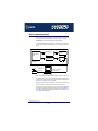
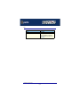
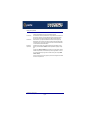
Document navigation
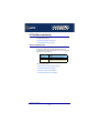
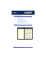
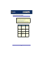
This manual features document navigation hypertext buttons in the header area as shown in
the next picture;
Jump to Using this on-line manual
Jump to Index
Jump to Quick reference
Jump to previous location
Jump to front of current chapter
Jump to Contents
Jump to Fast contents
Hypertext jumps
You can also navigate around this manual by clicking on any cross reference or text in blue
for example, Hypertext jumps.
Note
The Fast Contents, Contents and Index entries are all hypertext
jumps into this manual.
RIO Remote I/O System User Guide
Using this on-line manual
Page 5
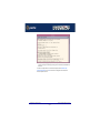
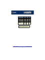
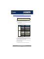
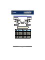
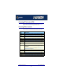
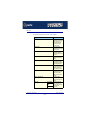
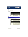
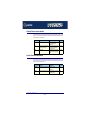
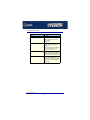
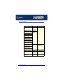
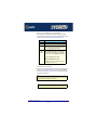
Revision history
Date
Part number
Description
January 1999
5500036-10
First issue of new RIO user manual for the Solaris operating system.
January 2000
5500036-11
Update of manual to include the Windows 2000 and Linux operating systems.
March 2000
5500036-12
Update of manual to include the Windows NT operating system.
March 2000
5500036-13
Update of manual to include the SCO OpenServer 5 operating system.
April 2000
5500036-14
Update of manual to include the SCO UnixWare operating system.
November 2001
5500036-15
Update of manual for rebranding.
October 2002
5500036-16
Update of manual to include 3.3V/5V universal PCI card.
September 2008
5500036-17
Update of manual installation instructions for Microsoft Server 2003/XP/Vista/
Server 2008 and OpenServer 6.
Page 6
RIO Remote I/O System
User Guide
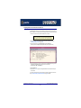
Fast Contents
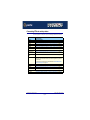
ABOUT THIS MANUAL ...........................................................................................................4
REVISION HISTORY ..............................................................................................................6
FAST CONTENTS .................................................................................................................7
CONTENTS ..........................................................................................................................8
CHAPTER 1 INTRODUCTION ..................................................................................................20
CHAPTER 2 INSTALLING HARDWARE AND SOFTWARE ............................................................31
CHAPTER 3 RIO CABLING INFORMATION ..............................................................................199
CHAPTER 4 QUICK REFERENCE ...........................................................................................226
CHAPTER 5 RIO COMMAND LINE UTILITIES ...........................................................................245
APPENDIX A SERIAL PORT DEVICE NAMES ............................................................................267
APPENDIX B TRANSPARENT PRINTING (SOLARIS ONLY) ........................................................269
APPENDIX C TROUBLESHOOTING .........................................................................................274
APPENDIX D CONTACTING PERLE ........................................................................................318
INDEX ..................................................................................................................................324
RIO Remote I/O System User Guide
Page 7
RIO Remote I/O System
User Guide
Contents
ABOUT THIS MANUAL ............................................................ 4
Purpose of this manual ..................................................................................4
Who this manual is for ...................................................................................4
Using this on-line manual ..............................................................................5
Document navigation ................................................................................5
Hypertext jumps ........................................................................................5
REVISION HISTORY ................................................................ 6
FAST CONTENTS ................................................................... 7
CONTENTS ............................................................................ 8
RIO Remote I/O System User Guide
Page 8
CHAPTER 1 INTRODUCTION
20
About the RIO system ....................................................................................21
RIO system components ...............................................................................22
Host card...................................................................................................22
Link cables ................................................................................................22
Remote Terminal Adaptors .......................................................................23
Long Distance Module (LDM) ...................................................................23
Fibre optic (FOLK) kit................................................................................24
Example RIO systems ....................................................................................25
Short distance link using RIO link cable....................................................26
Medium distance link using fibre optic (FOLK) kit .....................................27
Long distance link via leased line .............................................................28
Fault tolerant link.......................................................................................29
Dual host fail-safe link...............................................................................30
RIO Remote I/O System User Guide
Page 9
CHAPTER 2 INSTALLING HARDWARE AND SOFTWARE
31
Before you start ...............................................................................................33
Downloading RIO drivers from the Perle web site ...................................34
Installing RIO under Solaris ..........................................................................35
General setup procedure for Solaris .........................................................36
Upgrading from existing device drivers.....................................................38
Upgrading your current RIO driver............................................................38
Installing device drivers and utilities..........................................................39
Assigning ISA host card addresses and IRQ levels..................................41
Removing RIO drivers and utilities from your system ...............................42
Setting up terminals using Admintool........................................................44
Removing RIO serial port terminals ..........................................................49
Updating your RIO system configuration ..................................................51
Installing RIO under SCO OpenServer 5 and SCO OpenServer 6 .........52
General installation procedure for SCO OpenServer 5 and SCO OpenServer 6
53
Installing device drivers and utilities..........................................................54
Removing device drivers and utilities from your system ...........................62
Configuring ports with config.rio................................................................64
Adding an RTA to the system....................................................................65
Removing an RTA from the system ..........................................................69
Creating a login for an RTA.......................................................................72
Installing RIO under SCO UnixWare ............................................................76
General installation procedure for SCO UnixWare ...................................77
Installing device drivers and utilities..........................................................78
Assigning ISA host card address and IRQ levels .....................................79
Configuring ports with config.rio................................................................82
Adding an RTA to the system....................................................................83
Removing an RTA from the system ..........................................................86
Removing device drivers and utilities from your system ...........................89
Creating a login for an RTA.......................................................................89
RIO Remote I/O System User Guide
Page 10
Installing RIO under Windows NT ................................................................90
General setup procedure for Windows NT................................................91
Installing device drivers and utilities..........................................................92
Configuring ISA host cards .......................................................................95
Configuring PCI host cards .......................................................................98
Configuring Remote Terminal Adaptors ....................................................99
Making and displaying changes to your system configuration..................101
Introduction .................................................................................................... 102
Displaying multiple networks ......................................................................... 103
Printing a copy of the system map ................................................................ 103
Identifying an RTA ......................................................................................... 104
Displaying a port configuration summary ...................................................... 105
Adding a Fault Tolerant Link .......................................................................... 106
Adding an RTA to your system configuration ................................................ 106
Adopting Port Names .................................................................................... 107
Moving an RTA .............................................................................................. 108
Removing an RTA ......................................................................................... 108
Disconnecting an RTA from within the software ............................................ 108
Re-booting an RTA ........................................................................................ 109
Adding a Host Card ....................................................................................... 109
Removing a Host Card .................................................................................. 109
Installing RIO PCI Host Cards under Windows 2000/XP/Server 2003/Vista/
Server 2008 .......................................................................................................110
General setup procedure for Windows 2000/XP/Server 2003/Vista/Server
2008 ..........................................................................................................111
Installing PCI card drivers and utilities ......................................................112
Configuring PCI Card serial ports .............................................................115
Configuring the polled mode and quick close settings for a PCI host card118
Removing PCI devices and ports from the system ...................................121
Identifying PCI RTAs .................................................................................122
Installing RIO ISA Host Cards under Windows 2000 ...............................125
General setup procedure for Windows 2000 ............................................126
Adding ISA host cards to the system ........................................................127
Viewing and changing the resources for an ISA device............................130
Configuring ISA Card serial ports .............................................................133
Configuring the quick close settings for an ISA host card.........................136
Removing ISA devices and ports from the system ...................................139
Identifying ISA RTAs .................................................................................140
RIO Remote I/O System User Guide
Page 11
Installing RIO under Linux .............................................................................143
General installation procedure for Linux ...................................................144
Installing drivers onto your system............................................................145
Installing utilities ........................................................................................147
Creating devices for the attached ports ....................................................148
Loading the driver module into the kernel.................................................150
Manually loading the module and firmware ................................................... 150
Loading the RIO module and firmware automatically .................................... 151
Adding ports to the system .......................................................................153
Removing ports from a system .................................................................155
Installing a Universal 3.3/5V PCI host card ................................................156
Identifying your RIO PCI card and slot type..............................................156
Installation procedure................................................................................157
Installing an ISA host card ............................................................................158
Removing host cards .....................................................................................160
Installing Remote Terminal Adaptors (RTAs) ............................................161
RTA8 8 port Remote Terminal Adaptors ...................................................162
Installation procedure .................................................................................... 162
Wall mounting an RTA8 ................................................................................. 164
RTA16 16 port Remote Terminal Adaptors ...............................................165
Installation procedure .................................................................................... 165
RRC16 Remote Concentrator...................................................................168
Installation procedure .................................................................................... 168
Mounting the RRC16 ..................................................................................... 170
Removing a Remote Terminal Adaptor (RTA) ...........................................173
Installing a short distance link ......................................................................174
Installing a Fibre Optic Link Kit (FOLK) ......................................................175
Introduction ...............................................................................................175
Fibre optic unit main components .............................................................175
Installation procedure................................................................................176
RIO Remote I/O System User Guide
Page 12
Installing a Long Distance Module (LDM) ..................................................177
Introduction ...............................................................................................177
Long Distance Unit main components ......................................................178
Installation.................................................................................................179
General procedure ........................................................................................ 179
Installing a long distance LDM link via Modem and leased line .................... 180
Long wire installation ..................................................................................... 182
X.21 Installation ............................................................................................. 183
LDM Cabling information ..........................................................................184
LDU flying lead connector pinouts ............................................................184
Cable diagram ............................................................................................... 184
Mini DIN on RIO link flying lead .................................................................... 184
DB25 female on flying lead ........................................................................... 185
Adaptor pinouts for LDU flying lead connectors........................................186
Asynchronous Long-wire Connection (DB25 male to DB25 male) ................ 186
Asynchronous/Synchronous Modem & X21bis (DB25 female to DB25 male) 187
Synchronous X.21 connection ....................................................................... 188
Installing a fault tolerant link .........................................................................189
Installing a dual host fail-safe link (UNIX only) ..........................................190
Installing a dual host failsafe link under Solaris ........................................191
Installing for normal operation ....................................................................... 191
Transferring control to the slave system ........................................................ 194
Installing a dual host failsafe link under SCO OpenServer .......................195
Installing for normal operation ....................................................................... 195
Transferring control to the slave system ........................................................ 196
Installing a dual host failsafe link under SCO UnixWare...........................197
Installing for normal operation ....................................................................... 197
Transferring control to the slave system ........................................................ 198
RIO Remote I/O System User Guide
Page 13
CHAPTER 3 RIO CABLING INFORMATION
199
Mini DIN pinouts on RIO host cards ............................................................200
RTA connector pinouts ..................................................................................201
RTA connector guide.................................................................................201
RJ45 female RTA connector pinout ..........................................................202
DB25 female RTA connector pinout..........................................................203
RS422 DB25 female RTA connector pinout..............................................204
DB25 male RTA connector pinout.............................................................205
DB25 parallel female RTA connector pinout .............................................206
Connecting RIO host cards to RTAs ...........................................................207
Connecting RTAs to terminals .....................................................................207
Connecting RTAs to modems ......................................................................208
Connecting RTAs to parallel printers ..........................................................209
Connecting RTAs to serial printers .............................................................210
Cable connector pinouts ...............................................................................211
RJ45 male to DB25 male DTE for connection to DCE devices ................212
Cable diagram ............................................................................................... 212
Connector pinout table .................................................................................. 212
DB25 male to DB25 male DTE for connection to DCE devices ................213
Cable diagram ............................................................................................... 213
Connector pinout table .................................................................................. 213
DB25 female to DB25 male DTE for connection to DCE devices.............214
Cable diagram ............................................................................................... 214
Connector pinout table .................................................................................. 214
RJ45 male to DB25 female DCE for connection to DTE devices .............215
Cable diagram ............................................................................................... 215
Connector pinout table .................................................................................. 215
DB25 male to DB25 female DCE for connection to DTE devices.............216
Cable diagram ............................................................................................... 216
Connector pinout table .................................................................................. 216
DB25 female to DB25 female DCE for connection to DTE devices..........217
Cable diagram ............................................................................................... 217
Connector pinout table .................................................................................. 217
DB25 parallel male to centronics parallel..................................................218
RIO cables available from Perle ...................................................................219
Link Cable .................................................................................................219
Cable diagram ............................................................................................... 219
Connector pinout table .................................................................................. 219
Link cable specification .............................................................................220
RIO Remote I/O System User Guide
Page 14
Fibre optic link (FOLK) cable specifications ..............................................221
Loopback connector pinouts .......................................................................222
Loopback pinouts for RJ45 female connectors.........................................223
Loopback pinouts for DB25 female connectors ........................................224
Loopback pinouts for DB25 male connectors ...........................................225
RIO Remote I/O System User Guide
Page 15
CHAPTER 4 QUICK REFERENCE
226
SCO OpenServer 5 utilities ...........................................................................227
config.rio ...................................................................................................227
Main menu ..................................................................................................... 228
RTA Management menu ................................................................................ 229
Host Configuration menu ............................................................................... 232
SCO UnixWare utilities ...................................................................................233
Device configuration utility ........................................................................233
config.rio ...................................................................................................234
Main menu ..................................................................................................... 235
RTA Management menu ................................................................................ 237
Host Configuration menu ............................................................................... 239
spxadmport utility for configuring ports ....................................................240
Window NT utilities .........................................................................................242
RIO Configuration utility ............................................................................242
Main window .................................................................................................. 242
Menu map and toolbar buttons ...................................................................... 243
RIO Remote I/O System User Guide
Page 16
CHAPTER 5 RIO COMMAND LINE UTILITIES
245
Command line utilities ...................................................................................246
rioisacfg utility ...........................................................................................246
rioconfig utility ...........................................................................................247
RIO system commands under Solaris/Linux/LynxOS .............................248
rioreboot....................................................................................................249
rioversion ..................................................................................................250
rioboot .......................................................................................................251
rioadopt .....................................................................................................252
riodelete ....................................................................................................253
rioidentify...................................................................................................254
riolock........................................................................................................255
rioresume ..................................................................................................255
riomkdev ...................................................................................................256
rioshow......................................................................................................258
riostats ......................................................................................................259
rio.cf file .............................................................................................................260
About the rio.cf file ....................................................................................260
rio.cf keywords ..........................................................................................262
HOST ............................................................................................................ 263
RTA ................................................................................................................ 263
DEFPORT ..................................................................................................... 264
PORT ............................................................................................................. 266
RIO Remote I/O System User Guide
Page 17
APPENDIX A SERIAL PORT DEVICE NAMES
267
Solaris Device node details ...........................................................................268
Linux Device node details .............................................................................268
APPENDIX B TRANSPARENT PRINTING (SOLARIS ONLY)
269
What is transparent printing? .......................................................................270
Problems with printer output ........................................................................271
Sample transparent printing "rio.cf" port entry ........................................272
Common Terminal Transparent Print Sequences ...................................273
APPENDIX C TROUBLESHOOTING
274
Solaris troubleshooting .................................................................................275
Example of normal boot up messages for host cards...............................275
Troubleshooting guide...............................................................................276
Host cards ..................................................................................................... 276
Remote Terminal Adaptors (RTAs) ................................................................ 277
Ports .............................................................................................................. 278
SCO OpenServer 5 troubleshooting ...........................................................279
Using the Port Diagnostics facility.............................................................279
General procedure for using Port Diagnostics .............................................. 280
Selecting the RTA and port to test ................................................................. 281
Performing the send data to port test ............................................................ 285
Performing the loopback test on a port ......................................................... 287
SCO OpenServer 5 Error Messages ........................................................289
SCO UnixWare troubleshooting ...................................................................290
Using the Port Diagnostics facility.............................................................290
General procedure for using Port Diagnostics .............................................. 291
Selecting the RTA and port to test ................................................................. 292
Performing the send data to port test ............................................................ 295
Performing the loopback test on a port ......................................................... 297
SCO UnixWare Error Messages ...............................................................299
RIO Remote I/O System User Guide
Page 18
Windows NT troubleshooting .......................................................................300
General fault finding under Windows NT ..................................................301
Machine fails to boot ..................................................................................... 301
NT operating system fails while loading ........................................................ 302
RIO driver or another driver fails to boot ....................................................... 302
COM ports are not accessible ....................................................................... 303
RIO NT driver is operating satisfactorily but then fails .................................. 303
Error Messages.........................................................................................305
Messages which are common: ...................................................................... 306
Messages which are infrequent: .................................................................... 307
Messages which you should rarely see: ........................................................ 308
Clashing memory address ............................................................................. 309
Clashing Interrupts ........................................................................................ 310
System Information ....................................................................................... 311
Testing RIO host cards with the Hardware Diagnostics program..............312
How to run a test using RIO Hardware Diagnostics ...................................... 313
Test options guide ......................................................................................... 315
Additional options .......................................................................................... 317
APPENDIX D CONTACTING PERLE
318
Making a technical Support Query ..............................................................319
Who to contact ..........................................................................................319
Information needed when making a query................................................320
Making a support query via the Perle web page .......................................321
Repair procedure ............................................................................................322
Feedback about this manual ........................................................................322
Contacting Perle technical support .............................................................323
INDEX ................................................................................... 324
RIO Remote I/O System User Guide
Page 19
RIO Remote I/O System
User Guide
Chapter 1 Introduction
You need to read
this chapter if you
want to...
You need to read this chapter if you want an introduction to the Perle RIO serial connectivity
system.
This chapter provides introductory information about the Perle RIO serial connectivity
system, its associated components, driver software and configuration utilities.
This chapter includes the following sections;
•
About the RIO system on page 21
•
RIO system components on page 22
•
Example RIO systems on page 25
RIO Remote I/O System User Guide
Chapter 1 Introduction
Page 20
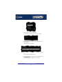
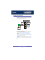
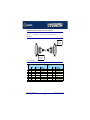
About the RIO system
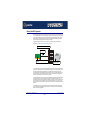
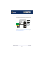
RIO is a high throughput serial connectivity system which provides up to 128 serial devices
via a single server slot. You can expand a RIO system up to 512 ports per server. RIO allows
you to add ports using 8 and 16 port modules which can be supplied with a wide range of
serial interfaces. The RIO system has fault tolerant capabilities, and allows long distance
connection without signal degradation or performance loss.
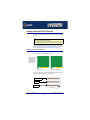
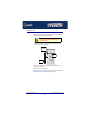
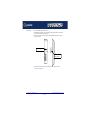
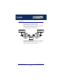
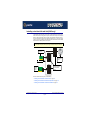
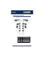
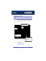
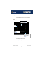
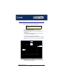
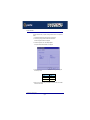
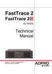
A typical RIO system is shown in the next picture. For details of the main RIO system
components, see RIO system components on page 22.
RIO Remote Terminal Adaptor (RTA)
RIO link cable
RIO ISA or Universal 3.3V/5V PCI
Host card
Peripheral, for
example printer
You use RIO when you need a system which supports fault tolerant cabling. The RIO system
allows you to add and remove port modules while the system is “live”, which means you can
reconfigure without interrupting operations. The relocated units retain their original port
names and settings. This capability is especially useful in the case of cable disruption, and
also for situations where complete data security is required. In addition, RIO supports the
connection of a stand-by host in case of server crashes.
You also use RIO because you require a system that allows long distance connection without
signal degradation or performance loss. RIO allows you to install port modules up to 75
metres from the host card using twisted pair cabling. Furthermore you can extend the range
by daisy chaining devices. In addition, you can connect port modules up to 1Km from the
host via copper wire or fibre optic, or longer distances via leased line, using RIO connectivity
modules.
You use RIO where you need a system that you can reconfigure live without interrupting
system operation. This capability is typically used in environments such as manufacturing
plants, test suites and hospitals.
RIO Remote I/O System User Guide
About the RIO system
Chapter 1 Introduction
Page 21
RIO system components
This section provides a brief description of the main components of the RIO system and
includes the following.
•
Host card on page 22
•
Link cables on page 22
•
Remote Terminal Adaptors on page 23
•
Long Distance Module (LDM) on page 23
•
Fibre optic (FOLK) kit on page 24.
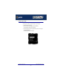
Host card
RIO host cards provide system connection to Remote Terminal Adaptors (RTAs). They have
four link ports and are available in ISA and PCI formats. See also Installing a Universal 3.3/
5V PCI host card on page 156, Installing an ISA host card on page 158 and Removing
host cards on page 160 in Chapter 2 Installing hardware and software.
Link cables
Link cables allow you to link host cards to Remote Terminal Adaptors (RTAs). See also Link
Cable on page 219 in Chapter 3 RIO Cabling information.
RIO Remote I/O System User Guide
RIO system components
Chapter 1 Introduction
Page 22
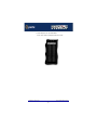
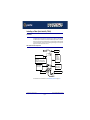
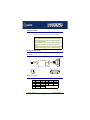
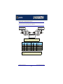
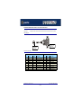
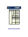
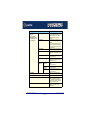
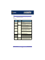
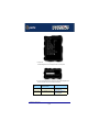
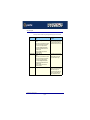
Remote Terminal Adaptors
Remote Terminal Adaptors (RTAs) are basically serial connection blocks which provide a
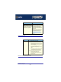
number of ports depending on type. RTAs come in three main varieties, the RTA 8 (providing
8 ports) and RTA 16 and RRC16 (providing 16 ports). Each unit is available in a number of
variations as shown in the next table.
Number
of ports
RTA type
Type
For details of installation see...
Currently available products
RRC16/RJX
16
High speed RS232 asynchronous
RJ45 serial ports with ESD
protection
RRC16 Remote
Concentrator on page 168
RTA8RJX
8
RS232 RJ45 with ESD protection
RTA8/RJ
8
RS232 RJ45
RTA8 8 port Remote Terminal
Adaptors on page 162
RTA8/DX
8
RS232 DB25 Female/ESD
Protected
RTA8/D
8
RS232 DB25 Female
RTA8/MX*
8
RS232 DB25 Male/ESD Protected
RTA8/M
8
RS232 DB25 Male
RTA8/PX*
8
Comprising 1 Centronics Parallel
DB25, 7 RS232 DB25 Female/ESD
Protected
RTA8/P
8
Comprising 1 Centronics Parallel
DB25, 7 RS232 DB25 Female
RTA8/422
8
RS422 DB25 Female
RTA16/DX
16
RS232 DB25 with ESD protection
RTA16/D
16
RS232 DB25 Female
Older products
RTA16 16 port Remote
Terminal Adaptors on page 165
See also Installing Remote Terminal Adaptors (RTAs) on page 161 in Chapter 2
Installing hardware and software.
Long Distance Module (LDM)
The RIO Long Distance Module (LDM) allows you to extend your RIO system via a leased
line. Using a RIO Long Distance Module you can make connections over thousands of miles
using synchronous (X.21/X.21bis) or asynchronous interfaces. The long distance module
comprises two long distance units (LDUs). One is installed at the host site and the other at
the remote site. See also Installing a Long Distance Module (LDM) on page 177 in
Chapter 2 Installing hardware and software.
RIO Remote I/O System User Guide
RIO system components
Chapter 1 Introduction
Page 23
Fibre optic (FOLK) kit
The RIO fibre optic (FOLK) kit allows you to extend the range of a RIO link via fibre optic
cable to a distance of up to one kilometre. The kit comprises two fibre optic modules. Each
module consists of a 1metre long RIO link cable connected to a fibre optic converter. The
fibre optic cable plugs into one of these converters at each end. See also Installing a Fibre
Optic Link Kit (FOLK) on page 175 in Chapter 2 Installing hardware and software.
RIO Remote I/O System User Guide
RIO system components
Chapter 1 Introduction
Page 24
Example RIO systems
This section provides typical examples of the main RIO system types.
Note
The Remote Terminal Adaptors shown in the following examples are 8
port RTA8s. For details of the different types of RTAs available see
Remote Terminal Adaptors on page 23.
The example systems described are as follows;
•
Short distance link using RIO link cable on page 26
•
Medium distance link using fibre optic (FOLK) kit on page 27
•
Long distance link via leased line on page 28
•
Fault tolerant link on page 29
•
Dual host fail-safe link on page 30.
To install any of these, first refer to Before you start on page 33 in Chapter 2 Installing
hardware and software in this manual.
RIO Remote I/O System User Guide
Example RIO systems
Chapter 1 Introduction
Page 25
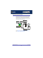
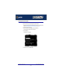
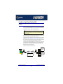
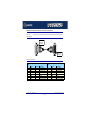
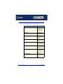
Short distance link using RIO link cable
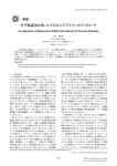
For short distances up to 75 metres you can use the RIO link cable to make up a basic RIO
system as shown in the next picture. Typically, you use this type of system when you want to
connect peripherals to the host within the same building.
RIO Remote Terminal Adaptor (RTA)
Peripheral, for
example printer
RIO link cable
RIO ISA or PCI
Host card
See also Before you start on page 33 and Installing a short distance link on page 174 in
Chapter 2 Installing hardware and software.
RIO Remote I/O System User Guide
Example RIO systems
Chapter 1 Introduction
Page 26
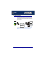
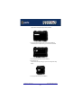
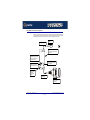
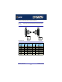
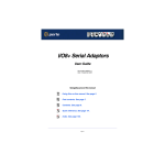
Medium distance link using fibre optic (FOLK) kit
The RIO fibre optic (FOLK) kit allows you to extend the range of a RIO link via fibre optic
cable to a distance of up to one kilometre. The kit comprises two fibre optic modules. (A
module is shown on page 175). Each module consists of a 1 metre long RIO link cable
connected to a fibre optic converter. This converts the transputer signals into light. The fibre
optic cable plugs into one of these converters at each end.
RIO ISA or PCI
Host card
RIO link cable to RTA
on peripheral end
RIO link cable
RTA
Fibre optic converter
Peripheral
For example,
printer
Fibre optic patch lead
See also Before you start on page 33 and Installing a Fibre Optic Link Kit (FOLK) on
page 175 in Chapter 2 Installing hardware and software.
RIO Remote I/O System User Guide
Example RIO systems
Chapter 1 Introduction
Page 27
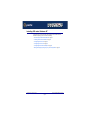
Long distance link via leased line
The RIO Long Distance Module (LDM) allows you to extend your RIO system via a leased
line. Using a RIO Long Distance Module you can make connections can over thousands of
miles using synchronous (X.21/X.21bis) or asynchronous interfaces. A typical remote system
is shown in the next picture.
Peripheral,
for example
printer
Host card
LDU
LDU
Modems connected
by leased line
RTA
For further details about this type of system see Before you start on page 33 and Installing
a Long Distance Module (LDM) on page 177 in Chapter 2 Installing hardware and
software.
RIO Remote I/O System User Guide
Example RIO systems
Chapter 1 Introduction
Page 28
Fault tolerant link
In a typical non fault tolerant RIO system, a host card is connected to a peripheral (for
example, a printer) via a single link and RTA. In order to make the system fault tolerant, that
is to protect against RTA or link failure, multiple RTAs and links are added.
The next picture shows a typical system which features two backup RTAs and a backup link
to the host. If one RTA or link cable is damaged there is still a path from the host and system
operation is not disrupted.
Multiple RTAs to
maintain operation
in event of RTA
failure
RIO Host card
Backup link to host
Peripheral
For example,
printer
For further information about installing a fault tolerant system, see Before you start on
page 33 and Installing a fault tolerant link on page 189 in Chapter 2 Installing hardware
and software.
RIO Remote I/O System User Guide
Example RIO systems
Chapter 1 Introduction
Page 29
Dual host fail-safe link
The RIO system supports the connection of a stand-by host in case of server crashes. A
typical example is shown in the next picture. In this system a second stand-by host has been
added which is installed in a separate server, thus if one host fails, system operation is still
maintained. Note that a fault tolerant link is often added between RTAs for additional
protection of the system.
RIO Host card
on server 1
Peripheral
For example,
printer
Fault tolerant link
Multiple RTAs to
maintain operation
in event of RTA
failure
Stand-by RIO Host
card on server 2
For information on how to install a dual host fail-safe system, see Before you start on
page 33 and Installing a fault tolerant link on page 189 in Chapter 2 Installing hardware
and software.
RIO Remote I/O System User Guide
Example RIO systems
Chapter 1 Introduction
Page 30
RIO Remote I/O System
User Guide
Chapter 2 Installing hardware and software
You need to read
this chapter if you
want to...
You need to read this chapter if you want to install a RIO system and associated
software.This chapter covers installing and configuring RIO hardware and software.
Note
The procedure for installing and configuring RIO serial adaptor cards varies for different
operating systems. Please read Before you start on page 33 before installation.
This chapter includes the following sections;
•
Before you start on page 33
•
Downloading RIO drivers from the Perle web site on page 34
•
Installing RIO under Solaris on page 35
•
Installing RIO under SCO OpenServer 5 and SCO OpenServer 6 on page 52
•
Installing RIO under SCO UnixWare on page 76
•
Installing RIO under Windows NT on page 90
•
Installing RIO PCI Host Cards under Windows 2000/XP/Server 2003/Vista/Server
2008 on page 110
•
Installing RIO ISA Host Cards under Windows 2000 on page 125
•
Installing RIO under Linux on page 143
•
Installing a Universal 3.3/5V PCI host card on page 156
•
Installing an ISA host card on page 158
•
Removing host cards on page 160.
•
Installing Remote Terminal Adaptors (RTAs) on page 161
•
Removing a Remote Terminal Adaptor (RTA) on page 173
•
Installing a short distance link on page 174
•
Installing a Fibre Optic Link Kit (FOLK) on page 175
•
Installing a Long Distance Module (LDM) on page 177
•
Installing a fault tolerant link on page 189
RIO Remote I/O System User Guide
Chapter 2 Installing hardware and software
Page 31
•
Installing a dual host fail-safe link (UNIX only) on page 190
RIO Remote I/O System User Guide
Chapter 2 Installing hardware and software
Page 32
Before you start
Before you install your RIO host cards and software, note that the procedure for installing
and configuring RIO serial adaptor cards varies for different operating systems.
To install under a particular operating system, please refer to one of the operating system
specific installation procedures listed below;
•
Installing RIO under Solaris on page 35.
•
Installing RIO under SCO OpenServer 5 and SCO OpenServer 6 on page 52
•
Installing RIO under SCO UnixWare on page 76
•
Installing RIO under Windows NT on page 90
•
Installing RIO PCI Host Cards under Windows 2000/XP/Server 2003/Vista/Server
2008 on page 110
•
Installing RIO under Linux on page 143.
RIO Remote I/O System User Guide
Before you start
Chapter 2 Installing hardware and software
Page 33
Downloading RIO drivers from the Perle web site
You can install the RIO driver and utility software from the Perle web site. To do this proceed
as follows;
1. On your PC, start the Internet browser you want to use (for example, Netscape).
2. Within your Internet browser window, select the software directory using the following
URL;
http://www.perle.com/downloads
Note
In the event of any problems contact your System Administrator or
Internet Service provider for assistance.
3. Select the directory you want from the list of operating system directories.
The selected operating system directory is now displayed.
4. Download the files in this directory to a suitable location on your PC for example, /tmp.
5. Follow the instructions for installing the software.
RIO Remote I/O System User Guide
Downloading RIO drivers from the Perle web site
Chapter 2 Installing hardware and software
Page 34
Installing RIO under Solaris
This section tells you how to install host cards, software drivers and utilities under the Solaris
operating system and includes the following;
•
General setup procedure for Solaris on page 36
•
Upgrading from existing device drivers on page 38
•
Upgrading your current RIO driver on page 38
•
Installing device drivers and utilities on page 39
•
Assigning ISA host card addresses and IRQ levels on page 41
•
Removing RIO drivers and utilities from your system on page 42
•
Setting up terminals using Admintool on page 44
•
Removing RIO serial port terminals on page 49
•
Updating your RIO system configuration on page 51.
Note
This version of RIO supports versions 2.6 and 7 of the Solaris operating system.
RIO Remote I/O System User Guide
Installing RIO under Solaris
Chapter 2 Installing hardware and software
Page 35
General setup procedure for Solaris
The general procedure for installing RIO for the Solaris operating system is as follows:
1. If required, install any PCI host cards you require into your system. See Installing a
Universal 3.3/5V PCI host card on page 156
2. Install the RIO Solaris drivers and utilities onto your system using the procedures
described in Installing device drivers and utilities on page 39.
3. If required, using the rioisacfg utility, select and assign addresses for any additional ISA
host cards you want to install from the free addresses available. See Assigning ISA host
card addresses and IRQ levels on page 41.
4. If required, install any ISA host cards you require into your system. See Installing an ISA
host card on page 158
5. If you want to remove any ISA host cards from your system,
a. at the command prompt, type:
/etc/rioisacfg [-d <name>] and press the Enter key
where <name> is the host card name (for example, ISA1) and d is the delete command.
b. Now physically remove any host cards you want from your system using the
procedures described in Removing host cards on page 160.
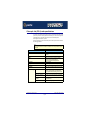
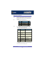
6. Install the links you require in your system using one of the procedures shown in the next
table;
Link type
For procedure see...
Short distance
Installing a short distance link on page 174
Medium distance
Installing a Fibre Optic Link Kit (FOLK) on page 175
Long distance
Installing a Long Distance Module (LDM) on page 177
Fault tolerant
Installing a fault tolerant link on page 189
Dual host fail-safe
Installing a dual host fail-safe link (UNIX only) on page 190
7. Install the Remote Terminal Adaptors you require for your system. see Installing Remote
Terminal Adaptors (RTAs) on page 161.
8. If required, remove any Remote Terminal Adaptors you want from your system. See
Removing a Remote Terminal Adaptor (RTA) on page 173.
9. Set up any terminals attached to your system using Admintool. See Setting up terminals
using Admintool on page 44.
10.If required remove any terminals from your system using Admintool. See Removing RIO
serial port terminals on page 49.
RIO Remote I/O System User Guide
Installing RIO under Solaris
Chapter 2 Installing hardware and software
Page 36
11.If you have made any changes to an existing RIO system, run the rioconfig utility to
update your system with the new configuration. See Updating your RIO system
configuration on page 51.
Your system is now ready for use. If required, you can reconfigure the system following initial
installation. See page 41 and page 44 for details.
RIO Remote I/O System User Guide
Installing RIO under Solaris
Chapter 2 Installing hardware and software
Page 37
Upgrading from existing device drivers
If your system already has an existing Perle device driver up to version 1.1.0 installed, you
cannot install a new device driver unless you follow the correct upgrade procedure. The
procedure required is as follows;
1. Remove the existing device driver using the procedure described in Removing RIO
drivers and utilities from your system on page 42.
2. Install the new device driver using the procedures described in Installing device drivers
and utilities on page 39.
3. Continue with your installation as required using the steps listed under General setup
procedure for Solaris on page 36.
Upgrading your current RIO driver
To upgrade your current RIO device driver, proceed as follows;
1. Follow the procedure for installing device drivers detailed in Installing device drivers
and utilities on page 39 using the upgrade options when prompted by the software.
2. Now follow the steps described in one of the procedures listed in the next table depending
on your operating system to complete the installation process.
Operating system
See procedure ...
Solaris
Installing device drivers and utilities on page 39.
RIO Remote I/O System User Guide
Installing RIO under Solaris
Chapter 2 Installing hardware and software
Page 38
Installing device drivers and utilities
To install the RIO device drivers and utilities for the Solaris operating system proceed as
follows;
Note
Before you install the RIO drivers and utilities you need to obtain the driver
package file ("riosol.pkg").
You can do this from either the CDROM (Solaris will automatically mount the
CDROM when inserted, and start the file manager application), or our website
(see Downloading RIO drivers from the Perle web site on page 34).
1. Login to your system as super user and begin a terminal session.
2. At the command prompt, type one of the commands shown in the next table depending
on the source of the riosol.pkg file you want to use;
Source of riosol.pkg file
Type this command
CDROM
Note x is version number
pkgadd -d /cdrom/drivers/rio/solaris/riosol.pkg
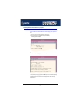
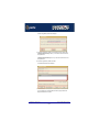
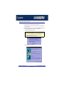
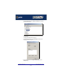
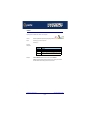
3. Press the Enter key.
The following question is now displayed:
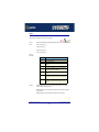
4. At the question prompt, type 1 and press the Enter key.
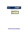
The following confirmation is now displayed as shown in the next picture.
RIO Remote I/O System User Guide
Installing RIO under Solaris
Chapter 2 Installing hardware and software
Page 39
5. At the question prompt, type y and press the Enter key.
A series of messages are now displayed ending with a confirmation that installation was
successful.
The drivers and utility software is now installed and operational.See General setup
procedure for Solaris on page 36 for instructions on adding ISA host cards, Remote
Terminal Adapters and Ports.
RIO Remote I/O System User Guide
Installing RIO under Solaris
Chapter 2 Installing hardware and software
Page 40
Assigning ISA host card addresses and IRQ levels
The rioisacfg Utility allows you to define addresses and IRQ levels for RIO host cards you
add to the system. You run this utility before installing the hardware using the following steps;
1. Decide on the name, memory address and IRQ level you require.
Note
You may need to reserve memory and Interrupt resources for ISA
cards using the system BIOS setup or system configuration program.
2. On each host card, set the address you want using the procedures described in
Installing an ISA host card on page 158.
3. At the command prompt, type /etc/rioisacfg and press the Enter key.
Some help text is now displayed which explains the syntax used by this utility.
4. At the command prompt, enter the command to start the rioisacfg utility using the card
parameters you decided in step 1. as shown in the next example:
/etc/rioisacfg -n ISA1 -m 0xD0000 -i 9
5. Press the Enter key.
6. Repeat steps 1. to 5. until you have assigned addresses to all the ISA host cards you
want to install.
You can now continue with the rest of the procedure required to install the host card. See
step 4. in General setup procedure for Solaris on page 36 for details.
RIO Remote I/O System User Guide
Installing RIO under Solaris
Chapter 2 Installing hardware and software
Page 41
Removing RIO drivers and utilities from your system
To remove the RIO device drivers and utilities for the Solaris operating system, proceed as
follows;
1. Login to your system as super user and begin a terminal session.
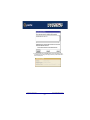
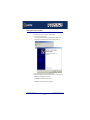
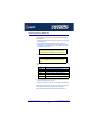
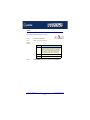
2. At the command prompt, type pkgrm rio and press the Enter key.
The following question is displayed:
3. At the question prompt, type y and press the Enter key.
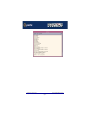
A further confirmation is displayed.
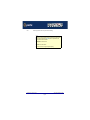
4. At the question prompt, type y and press the Enter key to remove the software package.
The messages shown in the next picture are now displayed and RIO driver and utility
software removed.
RIO Remote I/O System User Guide
Installing RIO under Solaris
Chapter 2 Installing hardware and software
Page 42
RIO Remote I/O System User Guide
Installing RIO under Solaris
Chapter 2 Installing hardware and software
Page 43
Setting up terminals using Admintool
To configure RIO serial ports added to the system proceed as follows;
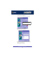
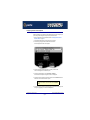
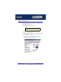
1. In the Solaris desktop, single click on the Application Manager toolbar icon shown in the
next picture.
Double click here to start
Application Manager.
The Application Manager window is now displayed.
2. In the Application Manager window, double click on the System_Admin folder.
The System_Admin window is now displayed.
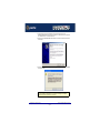
3. In the System_Admin window, double click on the Admintool icon.
The main Admintool window is now displayed as shown in the next picture.
RIO Remote I/O System User Guide
Installing RIO under Solaris
Chapter 2 Installing hardware and software
Page 44
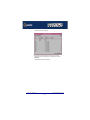
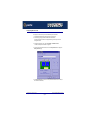
4. In the Admintool menu, click on Browse > Serial Ports.
RIO Remote I/O System User Guide
Installing RIO under Solaris
Chapter 2 Installing hardware and software
Page 45
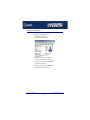
The Serial Ports window is now displayed.
5. In the Serial Ports window, double click on the serial port you want to modify.
Alternatively, click on the port to highlight it, then in the Serial Ports menu click on
Edit > Modify.
The Modify Serial Port window is now displayed.
RIO Remote I/O System User Guide
Installing RIO under Solaris
Chapter 2 Installing hardware and software
Page 46
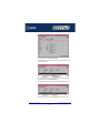
6. In the Modify Serial Port window, display basic information only by clicking on the Basic
button in the Detail field.
7. In the Modify Serial Port window, click on the Template selector and choose the type of
device you want to connect to the currently selected serial port. For example, to attach a
terminal to the serial port, select Terminal-Hardwired.
Hint
For details of the parameters in this field click on the help button to invoke the Solaris
on-line help about this window.
8. In the Modify Serial Port window, click in the Service Enable checkbox (displaying a tick)
to enable the currently selected serial port.
9. In the Modify Serial Port window, click on the Baud Rate selector and choose the Baud
rate you want. For example, 9600.
10.In the Terminal Type field, enter the terminal type you want.
Note
The terminal type you enter must be a valid terminal type as defined by the termcap file.
See the Solaris user documentation or on-line help for further details.
11.In the Modify Serial Port window, click on the OK
The currently selected serial port now has a terminal session enabled at the specified baud
rate, even parity, 7 data bits and 1 stop bit. The Serial Ports window is now updated to show
this as shown in the next picture.
RIO Remote I/O System User Guide
Installing RIO under Solaris
Chapter 2 Installing hardware and software
Page 47
12.Repeat steps 5. to 11. until you have configured all the RIO serial ports you require.
RIO Remote I/O System User Guide
Installing RIO under Solaris
Chapter 2 Installing hardware and software
Page 48
Removing RIO serial port terminals
To remove any RIO serial ports configured as terminals proceed as follows;
1. In the Solaris desktop, single click on the Application Manager toolbar icon shown in the
next picture.
Double click here to start
Application Manager.
The Application Manager window is now displayed.
2. In the Application Manager window, double click on the System_Admin folder.
The System_Admin window is now displayed.
3. In the System_Admin window, double click on the Admintool icon.
The main Admintool window is now displayed as shown in the next picture.
RIO Remote I/O System User Guide
Installing RIO under Solaris
Chapter 2 Installing hardware and software
Page 49
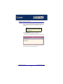
4. In the Admintool menu, click on Browse > Serial Ports
The Admintool window is now updated to show the serial ports available on the system as
shown in the next picture.
5. In the Admintool window, single click on the terminal you want to remove to highlight it.
6. In the Admintool menu, click on Select Edit > Delete.
The terminal entry for the serial port is now deleted and the Admintool window updated.
7. Repeat steps 5. to 6. until you have removed all the RIO terminal entries you require.
RIO Remote I/O System User Guide
Installing RIO under Solaris
Chapter 2 Installing hardware and software
Page 50
Updating your RIO system configuration
If you make any changes to your RIO system such as adding or removing an RTA for
example, you need to update your system using the rioconfig utility to recognise the revised
configuration.
Note
The rioconfig utility runs automatically when system first installed
(see Installing device drivers and utilities on page 39) and each
time you re-boot the system.
To do this proceed as follows;
•
At the command prompt, type rioconfig and press the Enter key.
The following message is now displayed followed by the return of the command prompt.
Your RIO and Solaris system files are is now updated to include the revised configuration
taking into account any new or removed RTAs and serial ports.
RIO Remote I/O System User Guide
Installing RIO under Solaris
Chapter 2 Installing hardware and software
Page 51
Installing RIO under SCO OpenServer 5 and SCO
OpenServer 6
This section tells you how to install host cards, software drivers and utilities under the SCO
OpenServer operating system and includes the following;
•
General installation procedure for SCO OpenServer 5 and SCO OpenServer 6 on
page 53
•
Installing device drivers and utilities on page 54
•
Configuring ports with config.rio on page 64
•
Adding an RTA to the system on page 65
•
Removing an RTA from the system on page 69
•
Creating a login for an RTA on page 72
RIO Remote I/O System User Guide
Installing RIO under SCO OpenServer 5 and SCO OpenServer 6
Chapter 2 Installing hardware and software
Page 52
General installation procedure for SCO OpenServer 5 and SCO OpenServer 6
The general procedure for installing and configuring host cards, Remote Terminal Adaptors
drivers software and associated utilities for the SCO OpenServer 5 and SCO OpenServer 6
operating system is as follows:
1. If required, install any PCI host cards you require into your system. See Installing a
Universal 3.3/5V PCI host card on page 156.
2. If required, install the RIO SCO OpenServer drivers and utilities onto your system using
the procedures described in Installing device drivers and utilities on page 54.
Note
To remove the RIO device drivers and utilities from your system, see
Removing device drivers and utilities from your system on
page 62
3. If required, install any ISA host cards you require into your system. See Installing an ISA
host card on page 158.
4. If required, remove any host cards you want from your system. See Removing host
cards on page 160.
5. Install or remove any Remote Terminal Adaptors you require onto your system. See
Installing Remote Terminal Adaptors (RTAs) on page 161 and Removing a Remote
Terminal Adaptor (RTA) on page 173.
6. Add any Remote Terminal Adaptors to your system configuration and setup as required
using the procedures given in Adding an RTA to the system on page 65.
7. Remove any Remote Terminal Adaptors from your system configuration as required
using the procedures given in Removing an RTA from the system on page 69.
Your system is now ready for use. If you add any RTAs to your system following initial
installation you need to can create logins for them using the procedures given in Creating a
login for an RTA on page 72.
RIO Remote I/O System User Guide
Installing RIO under SCO OpenServer 5 and SCO OpenServer 6
Chapter 2 Installing hardware and software
Page 53
Installing device drivers and utilities
To install the RIO device drivers and utilities for the SCO OpenServer operating system
proceed as follows;
1. Login to your system as super user.
2. Load the CDROM into your system CD drive.
3. At the command prompt, type mount -f ISO9660 -r /dev/cd0 /mnt and then press the
Enter key to mount the CDRO file system
4. In the SCO OpenServer desktop, double click on the System Administration folder.
The System Administration window is now displayed.
5. In the System Administration window, double click on the Software Manager icon.
The Software Manager window is now displayed.
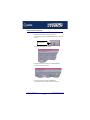
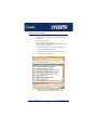
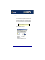
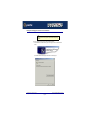
6. In the Software Manager menu, click on Software > Install New.
The Begin Installation window is now displayed as shown in the next picture.
RIO Remote I/O System User Guide
Installing RIO under SCO OpenServer 5 and SCO OpenServer 6
Chapter 2 Installing hardware and software
Page 54
Click here to
select the
local host as
the host
machine.
7. In the Begin Installation window, select the local host as the machine to install from by
clicking on the From localhostname button and then click on Continue.
The Select Media window is now displayed.
8. In the Select Media window, using the Media Device selector choose the Media Images
option then click on Continue.
RIO Remote I/O System User Guide
Installing RIO under SCO OpenServer 5 and SCO OpenServer 6
Chapter 2 Installing hardware and software
Page 55
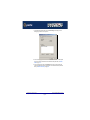
The Enter Image Directory window is now displayed.
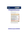
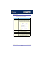
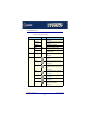
9. In the Enter Image Directory window, enter the following in the Image directory field;
/mnt/drivers/rio/openserver/x.y.z, where x.y.z is the version number of the driver for
SCO OpenServer 5.
/mnt/drivers/rio/openserver6/x.y.z, where x.y.z is the version number of the driver for
SCO OpenServer 6.
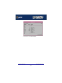
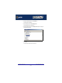
10.In the Enter Image Directory window, click on OK.
The Install Selection window is now displayed.
11.In the Install Selection window, click on the Install button.
If you are upgrading your current Perle RIO device driver, a pop-up window is now
displayed as shown in the next picture.
RIO Remote I/O System User Guide
Installing RIO under SCO OpenServer 5 and SCO OpenServer 6
Chapter 2 Installing hardware and software
Page 56
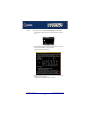
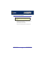
12.In the pop-up window, click on the Continue button to continue the installation process
The following progress message is now displayed, followed by the RIO Install window as
shown in the next pictures.
RIO Remote I/O System User Guide
Installing RIO under SCO OpenServer 5 and SCO OpenServer 6
Chapter 2 Installing hardware and software
Page 57
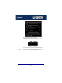
13.Now Press the Enter key to continue with your installation.
A prompt window is now displayed asking you if you wish to install ISA cards.
14.If you wish to install PCI cards now go to step 15. of this procedure, for ISA cards go to
step 19.
PCI cards
15.To configure PCI cards, at the Will you be installing ISA cards? prompt, select no
A message window is now displayed
RIO Remote I/O System User Guide
Installing RIO under SCO OpenServer 5 and SCO OpenServer 6
Chapter 2 Installing hardware and software
Page 58
16.Press the Enter key to close the message window and continue.
A message window is now displayed prompting you to select the operating mode for your
host cards.
17.In the message window, select the force into polled mode option and press the Enter
key
Note
We recommend using force into polled mode to avoid using up valuable interrupt
resources. Selecting this option does not produce any loss in performance.
A prompt window is now displayed asking you whether or not you wish to re-enter
hardware details.
18.At the prompt, select no.
Configuration of PCI cards is now completed.
RIO Remote I/O System User Guide
Installing RIO under SCO OpenServer 5 and SCO OpenServer 6
Chapter 2 Installing hardware and software
Page 59
ISA cards
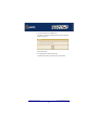
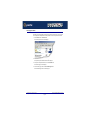
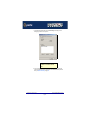
19.To configure ISA cards, at the Will you be installing ISA cards? prompt, select yes.
A prompt window now appears asking you for the number of ISA cards you are going to
install.
20.In the prompt window, use the up and down arrow keys to select the number of cards you
want and then press the Enter key to confirm your selection.
An address selection prompt is now displayed.
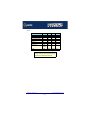
21.At the prompt, press either of the 1, 2, 3, or 4 keys to select the card you want then press
the Enter key to confirm your selection.
The address field is now highlighted as shown in the next picture.
RIO Remote I/O System User Guide
Installing RIO under SCO OpenServer 5 and SCO OpenServer 6
Chapter 2 Installing hardware and software
Page 60
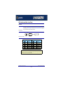
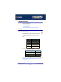
22.Using the keys shown in the next picture, set the address you want for the currently
selected host card. The press the Enter key to confirm your selection.
0d0000
Coarse address setting.
Set with up and down arrow keys
Fine address setting
Set with left and right arrow keys
23.Press the Enter key to continue the installation.
A prompt is now displayed asking whether or not you want to re-enter hardware details.
24.At the prompt, select no.
Configuration of ISA cards is now completed.
RIO Remote I/O System User Guide
Installing RIO under SCO OpenServer 5 and SCO OpenServer 6
Chapter 2 Installing hardware and software
Page 61
Removing device drivers and utilities from your system
To remove the RIO device drivers and utilities for the SCO OpenServer operating system
proceed as follows;
1. In the SCO OpenServer desktop, double click on the System Administration folder.
The System Administration window is now displayed.
2. In the System Administration window, double click on the software manager icon.
The Software Manager window is now displayed.
3. In the Software Manager window select the driver you want to remove.
4. In the Software Manager menu, click on Software > Remove software.
A confirmation window is now displayed prompting you to confirm removal
RIO Remote I/O System User Guide
Installing RIO under SCO OpenServer 5 and SCO OpenServer 6
Chapter 2 Installing hardware and software
Page 62
5. In the confirmation window, click on the Remove button.
The software is now removed and the following Kernel re-link message is now displayed
as shown in the next picture.
The Kernel re-link message window now closes and the removal continues. A message is
displayed upon completion.
6. In the message window, click on OK to close the window.
The software manager window is now updated to show the remaining software.
RIO Remote I/O System User Guide
Installing RIO under SCO OpenServer 5 and SCO OpenServer 6
Chapter 2 Installing hardware and software
Page 63
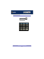
Configuring ports with config.rio
Under the SCO OpenServer operating system, RIO includes an application for configuring
ports called config.rio. Config.rio provides a real time map of your system showing the
Remote Terminal Adaptors, link cables and host cards and so forth that make up your
system.
Host card. Highlight a host card icon and
press the Enter key to display the
Host Configuration menu. See page 232.
Link cable
Click here or type M to display
Main Menu.
See page 228.
Remote Terminal Adaptor (RTA).
Highlight an RTA icon and press
the Enter key to display the
RTA Management Menu.
See page 232.
Any changes you make to your RIO system are automatically updated on the system map.
For details of using config.rio, see the following;
•
Adding an RTA to the system on page 65
•
Removing an RTA from the system on page 69
•
Creating a login for an RTA on page 72
RIO Remote I/O System User Guide
Installing RIO under SCO OpenServer 5 and SCO OpenServer 6
Chapter 2 Installing hardware and software
Page 64
Adding an RTA to the system
To add an RTA to your system configuration, proceed as follows;
1. Physically install the Remote Terminal Adaptor in your system using the procedures
detailed in Installing Remote Terminal Adaptors (RTAs) on page 161.
2. Login to your system as super user.
3. At the command prompt, type config.rio and press the Enter key.
The RIO configuration utility window is now displayed showing a map of your system. See
Configuring ports with config.rio on page 64 for more details about how config.rio
works.
4. In the RIO configuration utility window, highlight the unconfigured RTA you want to add to
the system.
Note
The way in which an unconfigured RTA is displayed depends on the types of
terminal being used. Normally, either the RTA icon flashes or appears in a
different colour.
RIO Remote I/O System User Guide
Installing RIO under SCO OpenServer 5 and SCO OpenServer 6
Chapter 2 Installing hardware and software
Page 65
5. Press the Enter key.
The RTA Management menu is now displayed.
6. In the RTA Management menu, click on Configure RTA.
A prompt window is now displayed asking you for a name for the selected RTA.
7. In the prompt window, enter the RTA name you want and press the Enter key.
The TTY configuration menu is now displayed.
8. In the TTY configuration menu, click on Use default TTY blocks and press the Enter
key.
You are now returned to the RTA Management menu.
RIO Remote I/O System User Guide
Installing RIO under SCO OpenServer 5 and SCO OpenServer 6
Chapter 2 Installing hardware and software
Page 66
9. If required, check your configuration settings as follows; In the RTA Management menu,
click on View RTA settings.
The RTA Settings window is now displayed as shown in the next picture.
10.If you are happy with the configuration settings press the ESC key to close the window.
Otherwise, repeat step 4. onwards of this procedure to change the configuration as
required.
Note
The changes you have made to the system configuration will not take
effect until you exit the config.rio utility.
11.Press the Esc key twice
A prompt window is now displayed asking you if you want to save changes before exiting
config.rio.
RIO Remote I/O System User Guide
Installing RIO under SCO OpenServer 5 and SCO OpenServer 6
Chapter 2 Installing hardware and software
Page 67
12.In the prompt window, select Yes and press the Enter key.
The config.rio utility now closes down and the system is updated to use your new
configuration.
Hint
To save and update the configuration changes without exiting proceed as follows;
•
In the Main Menu, click on Update configuration file.
RIO Remote I/O System User Guide
Installing RIO under SCO OpenServer 5 and SCO OpenServer 6
Chapter 2 Installing hardware and software
Page 68
Removing an RTA from the system
To remove an RTA from your system configuration, proceed as follows;
1. Physically remove the Remote Terminal Adaptor from your system using the procedures
detailed in Removing a Remote Terminal Adaptor (RTA) on page 173.
2. Login to your system as super user.
3. At the command prompt, type config.rio and press the Enter key.
The RIO configuration utility window is now displayed.
4. Press the Enter key.
The Main Menu is now displayed.
5. In the Main menu, click on Delete an RTA.
RIO Remote I/O System User Guide
Installing RIO under SCO OpenServer 5 and SCO OpenServer 6
Chapter 2 Installing hardware and software
Page 69
A popup window is now displayed showing the currently inactive RTAs.
6. In the pop-up window select the RTA you wish to remove and press the Enter key.
A confirmation prompt is now displayed, asking if you want to delete the selected RTA.
7. At the confirmation prompt, select Yes and press the Enter key.
8. Press the Esc key twice
A prompt window is now displayed asking you if you want to save changes before exiting
config.rio.
9. In the prompt window, select Y and press the Enter key.
RIO Remote I/O System User Guide
Installing RIO under SCO OpenServer 5 and SCO OpenServer 6
Chapter 2 Installing hardware and software
Page 70
The config.rio utility now closes down and the system is updated to use your new
configuration.
Hint
To save and update the configuration changes without exiting proceed as follows;
•
In the Main Menu, click on Update configuration file.
RIO Remote I/O System User Guide
Installing RIO under SCO OpenServer 5 and SCO OpenServer 6
Chapter 2 Installing hardware and software
Page 71
Creating a login for an RTA
To create a login for an RTA in your system configuration, proceed as follows;
1. Login to your system as super user.
2. At the command prompt, type config.rio and press the Enter key.
The RIO configuration utility window is now displayed.
3. In the RIO configuration utility window, highlight the RTA you want to create a login for
and then press the Enter key.
The RTA Management menu is now displayed.
RIO Remote I/O System User Guide
Installing RIO under SCO OpenServer 5 and SCO OpenServer 6
Chapter 2 Installing hardware and software
Page 72
4. In the RTA Management menu, click on View / edit TTY.
The View / edit TTY window is now displayed as shown in the next picture.
RIO Remote I/O System User Guide
Installing RIO under SCO OpenServer 5 and SCO OpenServer 6
Chapter 2 Installing hardware and software
Page 73
5. In the View / edit TTY window use the up and down arrow keys to select the TTY you
want to add a login to and press the Enter key.
The tty menu is now displayed.
6. In the tty menu, click on Getty entry and press the Enter key.
A pop-up window is now displayed showing the available getty definitions.
RIO Remote I/O System User Guide
Installing RIO under SCO OpenServer 5 and SCO OpenServer 6
Chapter 2 Installing hardware and software
Page 74
7. In the pop-up window, use the up and down arrow keys to select the getty definitions
entry you want to use and then press the Enter key.
The TTY types menu is now displayed as shown in the next picture.
8. In the TTY types menu select the terminal type you want to attach to the tty and press the
Enter key to return to the tty menu.
9. In the tty menu click on Enabled? and press the Enter key.
The TTY en/disable menu is now displayed.
10.In the TTY en/disable menu, click on TTY enabled and press the Enter key to return to
the tty menu.
11.Press the Esc key three times to exit config.rio.
RIO Remote I/O System User Guide
Installing RIO under SCO OpenServer 5 and SCO OpenServer 6
Chapter 2 Installing hardware and software
Page 75
Installing RIO under SCO UnixWare
This section tells you how to install host cards, software drivers and utilities under the SCO
UnixWare operating system and includes the following;
•
General installation procedure for SCO UnixWare on page 77
•
Installing device drivers and utilities on page 78
•
Assigning ISA host card address and IRQ levels on page 79
•
Configuring ports with config.rio on page 82
•
Adding an RTA to the system on page 83
•
Removing an RTA from the system on page 86
•
Removing device drivers and utilities from your system on page 89
•
Creating a login for an RTA on page 89
RIO Remote I/O System User Guide
Installing RIO under SCO UnixWare
Chapter 2 Installing hardware and software
Page 76
General installation procedure for SCO UnixWare
The general procedure for installing and configuring host cards, Remote Terminal Adaptors
drivers software and associated utilities for the SCO UnixWare operating system is as
follows:
1. If required, install any PCI host cards you require into your system. See Installing a
Universal 3.3/5V PCI host card on page 156.
2. If required, install the RIO SCO UnixWare drivers and utilities onto your system using the
procedures described in Installing device drivers and utilities on page 78.
Note
To remove the RIO device drivers and utilities from your system, see Removing
device drivers and utilities from your system on page 89.
3. If required, install any ISA host cards you require into your system. See Installing an ISA
host card on page 158.
4. If required, remove any host cards you want from your system. See Removing host
cards on page 160.
5. Install or remove any Remote Terminal Adaptors you require onto your system. See
Installing Remote Terminal Adaptors (RTAs) on page 161 and Removing a Remote
Terminal Adaptor (RTA) on page 173.
6. Add any Remote Terminal Adaptors to your system configuration and setup as required
using the procedures given in Adding an RTA to the system on page 83.
7. Remove any Remote Terminal Adaptors from your system configuration as required
using the procedures given in Removing an RTA from the system on page 86.
Your system is now ready for use. If you add any RTAs to your system following initial
installation you need to can create logins for them using the procedures given in Creating a
login for an RTA on page 89
RIO Remote I/O System User Guide
Installing RIO under SCO UnixWare
Chapter 2 Installing hardware and software
Page 77
Installing device drivers and utilities
To install the RIO device drivers and utilities for the SCO UnixWare operating system
proceed as follows;
1. Login to your system as root.
2. Load the CDROM into your system CD drive.
3. Mount the CDROM by typing the following at the command prompt;
mount -r -Fcdfs -0 nmconv=c /dev/cdrom/cdrom1 /mnt
Note
The exact syntax of this command may differ slightly on different versions of SCO
UnixWare. For details of exact syntax, please consult the documentation supplied with your
operating system.
4. Press the Enter key.
5. At the command prompt, type
pkgadd -d /mnt/drivers/rio/unixware/riouw.pkg rio and then press the Enter key.
A series of progress messages is now displayed finishing with thew command prompt.
6. Reboot your system.
The RIO device drivers and utilities for the SCO UnixWare are now installed and activated.
RIO Remote I/O System User Guide
Installing RIO under SCO UnixWare
Chapter 2 Installing hardware and software
Page 78
Assigning ISA host card address and IRQ levels
In order to function, each ISA host card must be allocated an available I/O address and IRQ
level. The Device Configuration Utility allows you to determine the available addresses and
IRQ levels, then allocate them to a particular host card. To do this proceed as follows;
1. At the command prompt, type dcu and press the Enter key.
The Unixware Device Configuration Utility window is now displayed.
2. In the DCU Main Menu, select the Software Device Drivers option and press the Enter
key
The Software Device Driver selections menu is now displayed.
RIO Remote I/O System User Guide
Installing RIO under SCO UnixWare
Chapter 2 Installing hardware and software
Page 79
3. In the Software Device Driver selections menu, click on the Communications Cards
option and press the Enter key.
The Software Device Drivers window is now displayed
4. In the Software Device Drivers window, select the RIO driver (hint use the arrow keys to
move the cursor) and then press the F5 key to add the new host card.
The New Hardware Configuration window is now displayed.
5. In the New Hardware Configuration window, set the parameters listed in the next table to
the values indicated.
Note
The MemStart and MemEnd values you set here must correspond to the values
set on the host card as detailed in Installing an ISA host card on page 158.
The IRQ level should be an IRQ that is not already in use by the system.
RIO Remote I/O System User Guide
Installing RIO under SCO UnixWare
Chapter 2 Installing hardware and software
Page 80
Parameter
Set to..
MemStart
MemEnd
d0000
dffff
IRQ level
15
6. Press the F10 key to accept the changes then press the Enter key to return to the
Software Device Driver Selections menu.
7. In the Software Device Driver Selections menu, select Return to DCU.
8. In the Device Configuration Utility Main Menu, select Apply Changes and Exit DCU.
9. Re-boot your system.
ISA host configuration is now complete.
RIO Remote I/O System User Guide
Installing RIO under SCO UnixWare
Chapter 2 Installing hardware and software
Page 81
Configuring ports with config.rio
Under the SCO UnixWare operating system, RIO includes an application for configuring
ports called config.rio. Config.rio provides a real time map of your system showing the
Remote Terminal Adaptors, link cables and host cards and so forth that make up your
system.
Host card. Highlight a host card icon and
press the Enter key to display the
Host Configuration menu. See page 232.
Link cable
Click here or type M to display
Main Menu.
See page 228.
Remote Terminal Adaptor (RTA).
Highlight an RTA icon and press
the Enter key to display the
RTA Management Menu.
See page 232.
Any changes you make to your RIO system are automatically updated on the system map.
For details of using config.rio, see the following;
•
Adding an RTA to the system on page 83
•
Removing an RTA from the system on page 86
RIO Remote I/O System User Guide
Installing RIO under SCO UnixWare
Chapter 2 Installing hardware and software
Page 82
Adding an RTA to the system
To add an RTA to your system configuration, proceed as follows;
1. Physically install the Remote Terminal Adaptor in your system using the procedures
detailed in Installing Remote Terminal Adaptors (RTAs) on page 161.
2. Login to your system as super user.
3. At the command prompt, type config.rio and press the Enter key.
The RIO configuration utility window is now displayed showing a map of your system. See
Configuring ports with config.rio on page 82 for more details about how config.rio
works.
4. In the RIO configuration utility window, highlight the unconfigured RTA you want to add to
the system.
Note
The way in which an unconfigured RTA is displayed depends on the types of
terminal being used. Normally, either the RTA icon flashes or appears in a
different colour.
5. Press the Enter key.
The RTA Management menu is now displayed.
RIO Remote I/O System User Guide
Installing RIO under SCO UnixWare
Chapter 2 Installing hardware and software
Page 83
6. In the RTA Management menu, click on Configure RTA.
A prompt window is now displayed asking you for a name for the selected RTA.
7. In the prompt window, enter the RTA name you want (for example, Sales or Ports 1-8)
and press the Enter key.
The TTY configuration menu is now displayed.
8. In the TTY configuration menu, click on Use default TTY blocks and press the Enter
key.
You are now returned to the RTA Management menu.
9. If required, check your configuration settings as follows; In the RTA Management menu,
click on View RTA settings.
The RTA Settings window is now displayed as shown in the next picture.
RIO Remote I/O System User Guide
Installing RIO under SCO UnixWare
Chapter 2 Installing hardware and software
Page 84
10.If you are happy with the configuration settings press the ESC key to close the window.
Otherwise, repeat step 4. onwards of this procedure to change the configuration as
required.
Note
The changes you have made to the system configuration will not take
effect until you exit the config.rio utility.
11.Press the Esc key twice
A prompt window is now displayed asking you if you want to save changes before exiting
config.rio.
12.In the prompt window, select Yes and press the Enter key.
The config.rio utility now closes down and the system is updated to use your new
configuration.
Hint
To save and update the configuration changes without exiting proceed as follows;
•
In the Main Menu, click on Update configuration file.
RIO Remote I/O System User Guide
Installing RIO under SCO UnixWare
Chapter 2 Installing hardware and software
Page 85
Removing an RTA from the system
To remove an RTA from your system configuration, proceed as follows;
1. Physically remove the Remote Terminal Adaptor from your system using the procedures
detailed in Removing a Remote Terminal Adaptor (RTA) on page 173.
2. Login to your system as super user.
3. At the command prompt, type config.rio and press the Enter key.
The RIO configuration utility window is now displayed.
4. Press the Enter key.
The Main Menu is now displayed.
5. In the Main menu, click on Delete an RTA.
RIO Remote I/O System User Guide
Installing RIO under SCO UnixWare
Chapter 2 Installing hardware and software
Page 86
A popup window is now displayed showing the currently inactive RTAs.
6. In the pop-up window select the RTA you wish to remove and press the Enter key.
A confirmation prompt is now displayed, asking if you want to delete the selected RTA.
7. At the confirmation prompt, select Yes and press the Enter key.
8. Press the Esc key twice
A prompt window is now displayed asking you if you want to save changes before exiting
config.rio.
9. In the prompt window, select Y and press the Enter key.
RIO Remote I/O System User Guide
Installing RIO under SCO UnixWare
Chapter 2 Installing hardware and software
Page 87
The config.rio utility now closes down and the system is updated to use your new
configuration.
Hint
To save and update the configuration changes without exiting proceed as follows;
•
In the Main Menu, click on Update configuration file.
RIO Remote I/O System User Guide
Installing RIO under SCO UnixWare
Chapter 2 Installing hardware and software
Page 88
Removing device drivers and utilities from your system
To remove the RIO device drivers and utilities from your system under SCO UnixWare,
proceed as follows;
1. Login to your system as root.
1. At the command prompt, type pkrm rio and then press the Enter key.
2. Re-boot your system.
Creating a login for an RTA
To create a login for an RTA under SCO UnixWare, you use the spxadmport utility. To do
this proceed as follows (this example uses a terminal 9600, 8,1, N on RIO port r001);
1. At the command prompt, type /etc/spxadmport add r001 9600R root and press the
Enter key.
Creation of the login is now complete. For more information about spxadmport, see
spxadmport utility for configuring ports on page 240 in Chapter 4 Quick Reference.
RIO Remote I/O System User Guide
Installing RIO under SCO UnixWare
Chapter 2 Installing hardware and software
Page 89
Installing RIO under Windows NT
This section tells you how to install host cards, software drivers and utilities under the
Windows NT operating system and includes the following;
•
General setup procedure for Windows NT on page 91
•
Installing device drivers and utilities on page 92
•
Configuring ISA host cards on page 95
•
Configuring PCI host cards on page 98
•
Configuring Remote Terminal Adaptors on page 99
•
Making and displaying changes to your system configuration on page 101
RIO Remote I/O System User Guide
Installing RIO under Windows NT
Chapter 2 Installing hardware and software
Page 90
General setup procedure for Windows NT
The general procedure for installing RIO for the Windows NT operating system is as follows:
1. If required, install any PCI host cards you require into your system. See Installing a
Universal 3.3/5V PCI host card on page 156.
2. Install the RIO Windows NT drivers and utilities onto your system using the procedures
described in Installing device drivers and utilities on page 92.
3. Using the RIO Configuration utility, add the names of any PCI cards to your system
configuration using the procedure given in Configuring PCI host cards on page 98.
4. Add your ISA host card settings to the system configuration. See Configuring ISA host
cards on page 95.
5. Install any ISA host cards you require into your system. See Installing an ISA host
card on page 158.
6. Install the links you require in your system using one of the procedures shown in the next
table.
Link type
For procedure see...
Short distance
Installing a short distance link on page 174
Medium distance
Installing a Fibre Optic Link Kit (FOLK) on page 175
Long distance
Installing a Long Distance Module (LDM) on page 177
Fault tolerant
Installing a fault tolerant link on page 189
Dual host fail-safe
Installing a dual host fail-safe link (UNIX only) on page 190
7. Install and remove Remote Terminal Adaptors as required for your system. see Installing
Remote Terminal Adaptors (RTAs) on page 161 and Removing a Remote Terminal
Adaptor (RTA) on page 173.
Note
If you connect a new device to your RIO system, for example an RTA, you need
to add the ports to the system using the procedures described in Making and
displaying changes to your system configuration on page 101.
8. Using the RIO Configuration utility, configure RTAs and associated serial ports you have
added to the system. See Configuring Remote Terminal Adaptors on page 99.
Your system is now ready for use. If required, you can reconfigure the system following initial
installation. See Making and displaying changes to your system configuration on
page 101 for details.
RIO Remote I/O System User Guide
Installing RIO under Windows NT
Chapter 2 Installing hardware and software
Page 91
Installing device drivers and utilities
To install the RIO device drivers on your system proceed as follows;
1. Turn on your PC and login to your system as administrator. Then load the CDROM into
your systems CD drive.
2. Start the windows Explorer (or file manager) and display the \drivers\rio\winnt\ directory.
3. In the \drivers\rio\winnt\ directory, double click on the setup.exe file.
The Install Shield window is briefly displayed.
Note
If you have previously installed RIO software, a warning message is now displayed
asking you to shutdown all RIO dependent devices. This is because the device
drivers updated during the installation process can only be updated properly if
communication to all RIO dependent devices is stopped.
The Welcome window is now displayed.
RIO Remote I/O System User Guide
Installing RIO under Windows NT
Chapter 2 Installing hardware and software
Page 92
4. In the Welcome window, click on the Next > button.
The Choose Destination window is now displayed as shown in the next picture.
If you want to use a directory other than the suggested
default, click on the Browse button then use the
browser displayed to select the directory you want.
5. In the Choose Destination window, click on the Next > button.
The Select Program Folder window is now displayed.
6. In the Select Program Folder window, select the folder to which you want to add the
program icons and click on the Next > button.
A progress message window is now displayed.
RIO Remote I/O System User Guide
Installing RIO under Windows NT
Chapter 2 Installing hardware and software
Page 93
Upon completion of the installation process a program group window is displayed showing
the RIO configuration icon.
RIO Remote I/O System User Guide
Installing RIO under Windows NT
Chapter 2 Installing hardware and software
Page 94
Configuring ISA host cards
To configure an ISA host card prior to actual installation proceed as follows;
1. In the Windows desktop, display the Perle program group window.
2. In the Perle program group window, double click on the RIO icon.
The RIO Configuration window is now displayed showing a blank map on the RIO
Configuration screen.
3. In the RIO Configuration menu, click on Commands > Add ISA host card.
The ISA Card Setup tabbed window now appears.
4. In the ISA Card Setup tabbed window, click on the Rotary Switches tab to display the
Rotary Switches page.
5. In the Rotary Switches page set the host card parameters detailed in the next table (if
the defaults are insufficient):
RIO Remote I/O System User Guide
Installing RIO under Windows NT
Chapter 2 Installing hardware and software
Page 95
Parameter
Action required
Host name
Change the default host name to whatever you wish
Select an IRQ
Select an IRQ value, or better, choose ‘Poll’ or ‘Auto’.
The default is polled mode, which is an alternative to IRQ level setting and
is useful when the range of available interrupts is restricted. If you choose
Poll, the driver will poll the card regularly for data. When installing more
than one card, set the IRQ value to Poll for all the cards.
The Auto interrupt option is an alternative to IRQ level setting and will
assign the first available interrupt. If you have reserved in the BIOS an IRQ
specifically for ISA cards, you need to select the IRQ number from the list
since the Auto option will not automatically use that reserved IRQ.
SW1 and SW2
To change the address of an ISA card fitted with rotary switches, click (or
use tab to highlight) the buttons marked SW1 and then SW2. Then use the
space bar to increment the address, watching the message output in the
bottom left of the dialogue box.
To change the address of an ISA card fitted with a DIL switch, click the
switches of the 10-way DIL switch displayed in the dialogue box.
Make a note of the settings; you will need to set them on the card itself.
6. In the ISA Card Setup tabbed window, click on the Apply button to save changes and
close the window.
The RIO driver will check that the memory address and interrupt that you have selected
are not already being used. If either resource is being used, you will be asked to reselect.
7. In the RIO Configuration window menu, click on File > Exit to exit the utility.
The Reboot Windows NT window is now displayed as shown in the next picture.
RIO Remote I/O System User Guide
Installing RIO under Windows NT
Chapter 2 Installing hardware and software
Page 96
8. In the Reboot WIndows NT window, click on the Launch RioConf check box to ensure
that the RIO Configuration utility is launched automatically the next time Windows is
restarted.
9. In the Reboot WIndows NT window, click on the Don’t Restart Windows button to avoid
restarting Windows before you have physically installed the host card.
10.Shutdown Windows and switch off your machine.
You can now install your ISA host cards. See Removing host cards on page 160.
RIO Remote I/O System User Guide
Installing RIO under Windows NT
Chapter 2 Installing hardware and software
Page 97
Configuring PCI host cards
The PCI host card is plug and play however, under Windows NT a small amount of
configuration is required. To install and configure a PCI card under Windows NT, proceed as
follows;
Note
Although plug and play, some machine BIOSs require that you assign IRQs to each
PCI slot in order to make a PCI card use interrupts.
You cannot change the interrupt or memory address of the PCI card.
1. Install the PCI host card into your system using the procedures detailed in Installing a
Universal 3.3/5V PCI host card on page 156.
2. Switch on your computer system.
Note
During bootup, the operating system will select automatically an interrupt and memory
address for the card.
3. In the Windows desktop, display the Perle program group window.
4. In the Perle program group window, double click on the RIO icon.
The RIO Configuration window is now displayed showing the RIO PCI card on the map
display.
5. In the RIO Configuration window, double-click on the card and give it a name.
You can now continue with the rest of your system installation as detailed in General setup
procedure for Windows NT on page 91.
RIO Remote I/O System User Guide
Installing RIO under Windows NT
Chapter 2 Installing hardware and software
Page 98
Configuring Remote Terminal Adaptors
Following installation of your Remote Terminal Adaptors (RTAs) you need to configure your
system using the RIO Configuration Utility. To do this proceed as follows:
1. Install your RTA units using the procedures detailed in Installing Remote Terminal
Adaptors (RTAs) on page 161.
1. In the windows desktop, display the Perle program group window.
2. In the Perle program group window, double click on the RIO icon.
The Rio Configuration window is now displayed.
3. In the Rio configuration window single click on the RTA you wish to select.
A red line should appear around the RTA symbol.
4. In the Rio Configuration Menu, click on Commands > Configure .
The Remote Terminal Adaptor Configuration window is now displayed.
5. In the Remote Terminal Adaptor Configuration window, click in the RTA Name field and
edit the RTA name and ident number as required.
Hint
To return to the default name for the card, click on the default
button.
6. In the Remote Terminal Adaptor Configuration window, single click on each port you want
to configure (highlighting it) then click on the Setup button.
RIO Remote I/O System User Guide
Installing RIO under Windows NT
Chapter 2 Installing hardware and software
Page 99
The Set Device Name window is now displayed.
7. In the Set Device name window, change the device name as required and click on the
Apply button.
Hint
We recommend using COM as the default port prefix. Any change that you do make
will only affect ports configured subsequently to the change.
To quicken the naming of ports in the Remote Terminal Adaptor Configuration
window select the Enumerate button. This action will allow you to number all
the remaining ports sequentially, using the currently selected port as the
starting number.
8. In the Remote Terminal Adaptor Configuration window, click on the Apply button to effect
your settings.
RIO Remote I/O System User Guide
Installing RIO under Windows NT
Chapter 2 Installing hardware and software
Page 100
Making and displaying changes to your system configuration
This section describes how to make and view changes made to your system following initial
configuration under Windows NT using the RIO configuration utility.
The following sections are provided;
•
Introduction on page 102
•
Displaying multiple networks on page 103
•
Printing a copy of the system map on page 103
•
Identifying an RTA on page 104
•
Displaying a port configuration summary on page 105
•
Adding a Fault Tolerant Link on page 106
•
Adding an RTA to your system configuration on page 106
•
Adopting Port Names on page 107
•
Moving an RTA on page 108
•
Removing an RTA on page 108
•
Disconnecting an RTA from within the software on page 108
•
Re-booting an RTA on page 109
•
Adding a Host Card on page 109
•
Removing a Host Card on page 109
•
Manually loading the module and firmware on page 150
RIO Remote I/O System User Guide
Installing RIO under Windows NT
Chapter 2 Installing hardware and software
Page 101
Introduction
Once you have installed your RIO system under Windows NT, you can view changes to your
RIO system using the RIO Configuration utility.The map(s) of the system displayed in the
RIO Configuration utility will respond automatically to changes to your RIO system.
Note
When the RIO Configuration utility is not running, The RIO software will store any changes to
your system and will update the display when you next run the RIO Configuration utility.
Note
In the event of link failure or disconnection, the broken link will disappear from the system
map displayed in the RIO Configuration window and any isolated RTAs on the system map
now appear greyed out.
As soon as the link is restored, the map is updated automatically to display the new or
resumed link. (RIO will remember the configuration of your RTA(s). There is no need to
reconfigure the unit(s).
RIO Remote I/O System User Guide
Installing RIO under Windows NT
Chapter 2 Installing hardware and software
Page 102
Displaying multiple networks
If you have more than one card installed, you can display the additional network(s) of RTAs
on the RIO Configuration utility in separate windows.
Hint
Use the Tile Option from the Windows menu to place the different
windows next to one another, so you can see all the networks
simultaneously.
Printing a copy of the system map
RIO allows you to print a copy of the system of the system map displayed in the RIO
Configuration utility. To do this proceed as follows;
1. In the RIO Configuration utility window, click on the File > Print menu option
2. Use the standard windows printing options now displayed to print a copy of your system
map.
Note
You can choose to print the whole topology or just a section of it.
RIO Remote I/O System User Guide
Installing RIO under Windows NT
Chapter 2 Installing hardware and software
Page 103
Identifying an RTA
To display the identity of an RTA on the system map proceed as follows;
1. In the windows desktop, display the Perle program group window.
2. In the Perle program group window, double click on the RIO icon.
The Rio Configuration window is now displayed showing a map of your RIO system.
3. In the Rio Configuration window, select the RTA(s) you wish to identify physically; (control
- click to select more than one RTA).
4. In the Rio Configuration menu, click on Commands > Identify.
The system map now displays a pulse moving along the link between the host card and
the selected RTA(s) and the LEDs are flashed on the actual RTAs you have identified.
Hint
If you wish to identify multiple RTAs, note the pattern of flashing lights visible on the
RTA symbols on the system map in the Rio Configuration window. The flashing
pattern is unique to each RTA, so you can then match the pattern of flashing LEDS
on the actual RTAs.
Pulse display
5. When you have finished identifying the RTAs you want, in the Rio configuration menu,
click on Commands > Stop identify to disable the identify feature.
The Identify feature now cancels (over the next 5 seconds) and the flashing lights cease on
both the RTA symbol and unit.
RIO Remote I/O System User Guide
Installing RIO under Windows NT
Chapter 2 Installing hardware and software
Page 104
Displaying a port configuration summary
RIO allows you to display a summary of configuration settings for each port. To do this
proceed as follows;
1. In the windows desktop, display the Perle program group window.
2. In the Perle program group window, double click on the RIO icon.
The Rio Configuration window is now displayed.
3. In the Rio Configuration menu, click on Windows > Summary.
The Summary window is now displayed.
4. In the Summary window, single click on a port in the RIO defined Ports list.
A configuration summary for the selected port is now displayed in the Summary window.
5. Repeat step 4. until you have viewed all the configuration summaries you require then
click on the Close button to close the window.
RIO Remote I/O System User Guide
Installing RIO under Windows NT
Chapter 2 Installing hardware and software
Page 105
Adding a Fault Tolerant Link
When you add a fault tolerant link to your RIO system it is displayed on the system map in a
diffident colour to normal links (usually grey). Fault tolerant links are detected and displayed
automatically in the RIO Configuration window in the same way as standard links.
For more information about fault tolerant links, see Fault tolerant link on page 29 and
Installing a fault tolerant link on page 189.
Adding an RTA to your system configuration
When you add additional RTAs to your system, they are added to the system map displayed
in the RIO Configuration window automatically. New RTAs will display their default names
and electronic serial numbers. To change these, see Identifying an RTA on page 104 and
Adopting Port Names on page 107.
Note
You can install up to 128 ports per host card. If you install one too many, RIO will
detect it but won’t be able to assign it an ID. On the system map, the RTA will
appear but without a link (despite you having physically connected it).
RIO Remote I/O System User Guide
Installing RIO under Windows NT
Chapter 2 Installing hardware and software
Page 106
Adopting Port Names
When you are installing a new RTA, the RIO Configuration utility allows you to adopt the port
names of RTAs no longer connected to the system (known as orphaned).Typically, you use
this facility because you want to replace a failed RTA or you are replacing an RTA with a unit
which has a different physical interface.
To adopt port names in this way proceed as follows;
1. In the RIO Configuration window, locate the on the orphaned RTA you want to use.
2. Connect the new RTA to your system. See Installing Remote Terminal Adaptors
(RTAs) on page 161.
The system map is now updated to show the new RTA.
3. In the RIO Configuration window, single click on the new RTA to select it.
4. In the RIO Configuration menu, click on Commands > Configure .
The Remote Terminal Adaptor Configuration window is now displayed.
5. In the Remote Terminal Adaptor Configuration window, click on the Adopt button.
The Adopt window is now displayed.
6. In the Adopt window, use the Orphaned RTA selector to choose the RTA whose ports you
want to adopt and then click on the Adopt button.
A caution message window now appears.
7. In the caution message window, click on the Proceed button to complete the adoption
process.
The orphaned RTA is now deleted from the system map.
RIO Remote I/O System User Guide
Installing RIO under Windows NT
Chapter 2 Installing hardware and software
Page 107
Moving an RTA
Under windows NT RIO allows you to relocate a previously configured RTA within your RIO
system without further configuration. The device driver will detect its ID and configuration
automatically, and will relocate the unit on the system map in the RIO Configuration window.
For details on installing RTAs, see Installing Remote Terminal Adaptors (RTAs) on
page 161.
Removing an RTA
To remove an RTA from your system under Windows NT proceed as follows;
1. Remove the RTA from your system using the procedures detailed in Removing a
Remote Terminal Adaptor (RTA) on page 173.
2. In the RIO Configuration window, single click on the RTA you want to remove from the
system.
3. In the RIO Configuration menu, click on Commands > Remove.
The ports that were assigned to the RTA are now added to the list of available ports.
Note
If you fail to delete RTAs from the system map configuration, the RIO system will assume the
ports associated with that RTA are still installed and subsequently reject any new RTAs added
to the system.
Disconnecting an RTA from within the software
The RIO configuration utility allows you to disconnect an RTA from the system without
physically unplugging it. This process is known as zombieing. To disconnect an RTA in this
way proceed as follows;
1. In the RIO Configuration window, single click on the RTA you want to zombie.
2. In the RIO Configuration menu, click on Commands > Zombie.
On the system map the RTA is now disconnected (orphaned) from the host and becomes
dimmed.
Note
To remove an RTA from a zombied state, go to the unit and re-power it. The map should
update itself to show the RTA connected once more.
RIO Remote I/O System User Guide
Installing RIO under Windows NT
Chapter 2 Installing hardware and software
Page 108
Re-booting an RTA
You can re-boot an RTA through the Configuration Utility, without going to the RTA unit:
1. In the RIO Configuration window, single click on the RTA you want to re-boot.
2. In the RIO Configuration menu, click on Commands > Reboot.
A pop-up window now appears asking you whether you wish to close ports before rebooting, or to re-boot and close ports simultaneously.
3. In the pop-up window, select the option you want and action your choice.
The selected RTA is now re-booted.
Adding a Host Card
When you add host cards to your system the configuration required by the user depends on
the type of host card you are installing as shown in the next table.
Host card
type
Action required
PCI
No action required by the user.
ISA
Use the procedure described in Configuring
ISA host cards on page 95.
Removing a Host Card
To remove a host card from your system under Windows NT proceed as follows;
1. Remove all the RTAs associated with the host card from your system using the
procedures detailed in Removing a Remote Terminal Adaptor (RTA) on page 173.
2. In the RIO Configuration window, single click on the host card you want to remove from
the system.
3. In the RIO Configuration menu, click on Commands > Remove.
The system map now shows the card as removed,
You can now shutdown your machine and remove the card. See Removing host cards on
page 160.
RIO Remote I/O System User Guide
Installing RIO under Windows NT
Chapter 2 Installing hardware and software
Page 109
Installing RIO PCI Host Cards under Windows 2000/XP/
Server 2003/Vista/Server 2008
This section describes how to install RIO PCI host cards under Microsoft Windows 2000/XP/
Server 2003/Vista/Server 2008.
This section includes the following:
•
General setup procedure for Windows 2000/XP/Server 2003/Vista/Server 2008 on
page 111
•
Installing PCI card drivers and utilities on page 112
•
Configuring PCI Card serial ports on page 115
•
Configuring the polled mode and quick close settings for a PCI host card on
page 118
•
Removing PCI devices and ports from the system on page 121
•
Identifying PCI RTAs on page 122.
RIO Remote I/O System User Guide
Installing RIO PCI Host Cards under Windows 2000/XP/Server 2003/Vista/Server 2008
Page 110
Chapter 2 Installing hardware and software
General setup procedure for Windows 2000/XP/Server 2003/Vista/Server 2008
The general procedure for installing RIO PCI host cards for the Windows 2000/XP/Server
2003/Vista/Server 2008 operating system is as follows:
1. If required, install any PCI host cards you require into your system. See Installing a
Universal 3.3/5V PCI host card on page 156.
2. Install and remove Remote Terminal Adaptors as required for your system. See
Installing Remote Terminal Adaptors (RTAs) on page 161 and Removing a Remote
Terminal Adaptor (RTA) on page 173.
Note
If you connect a new device to your RIO system, for example an RTA, the new
ports are added to the system automatically. No action is required by the user.
3. Install the RIO Windows 2000/XP/Server 2003/Vista/Server 2008 drivers and utilities onto
your system using the procedures described in Installing PCI card drivers and
utilities on page 112.
Note
The RTA must be installed to the PCI host card before the device drivers are
installed.
4. Install the links you require in your system using one of the procedures shown in the next
table;
Link type
For procedure see...
Short distance
Installing a short distance link on page 174
Medium distance
Installing a Fibre Optic Link Kit (FOLK) on page 175
Long distance
Installing a Long Distance Module (LDM) on page 177
Fault tolerant
Installing a fault tolerant link on page 189
Dual host fail-safe
Installing a dual host fail-safe link (UNIX only) on page 190
5. Using the Device Manager, configure the serial ports you have added to the system. See
Configuring PCI Card serial ports on page 115.
Your system is now ready for use. If required, you can reconfigure the system following initial
installation. See Configuring the polled mode and quick close settings for a PCI host
card on page 118, Removing PCI devices and ports from the system on page 121 for
details.
To identify an RTA from within the software. See Identifying PCI RTAs on page 122.
RIO Remote I/O System User Guide
Installing RIO PCI Host Cards under Windows 2000/XP/Server 2003/Vista/Server 2008
Page 111
Chapter 2 Installing hardware and software
Installing PCI card drivers and utilities
To install the RIO device drivers on your system proceed as follows:
1. Turn on your PC and if required, log in.
If you have installed any new host cards a Found New Hardware message is briefly
shown followed by the Found New Hardware wizard as shown in the pictures.
2. In the Found New Hardware wizard, click the Cancel button.
3. Download the lastest RIO driver zip file from the Perle website for your operating system:
rio-x86.zip for 32-bit Windows operating systems.
rio-amd64.zip for 64-bit Windows operating systems.
rio-ia64.zip for 64-bit Windows Itanium operating systems.
RIO Remote I/O System User Guide
Installing RIO PCI Host Cards under Windows 2000/XP/Server 2003/Vista/Server 2008
Page 112
Chapter 2 Installing hardware and software
4. Unzip the driver zip file to a local directory. We recommend that you use the
rio-setup-<arch>.exe file when installing the drivers for a RIO PCI card, which will launch
the installation wizard, to install the RIO driver.
5. Double-click the rio-setup-<arch>.exe installation executable and follow the installation
wizard steps:
6. During the installation, you may get a Windows Logo message. Click Continue Anyway
when these appear.
Note
If you are installing an unsigned driver, you may have to click through the Found New
Hardware wizard for every RIO card on your system.
RIO Remote I/O System User Guide
Installing RIO PCI Host Cards under Windows 2000/XP/Server 2003/Vista/Server 2008
Page 113
Chapter 2 Installing hardware and software
7. Your RIO driver installation is now finished.
RIO Remote I/O System User Guide
Installing RIO PCI Host Cards under Windows 2000/XP/Server 2003/Vista/Server 2008
Page 114
Chapter 2 Installing hardware and software
Configuring PCI Card serial ports
To configure RIO serial ports, proceed as follows:
1. Click the Start button > Control Panel
The control panel window is now displayed.
2. In the Control Panel window, click on the System icon.
The System Properties tabbed window is now displayed.
3. In the System Properties window, click on the Hardware tab.
The hardware page is now displayed.
4. In the Hardware page, click on the Device Manager Button.
The Device Manager window is now displayed.
RIO Remote I/O System User Guide
Installing RIO PCI Host Cards under Windows 2000/XP/Server 2003/Vista/Server 2008
Page 115
Chapter 2 Installing hardware and software
5. In the Device Manager window, click on the Multiport serial adapters icon to display the
currently installed devices.
6. In the Device Manager window, double click on the device whose properties you want to
view or change.
The device Properties tabbed window is now displayed.
7. In the device Properties window, click on the Port Settings tab to display the Port
Settings page.
RIO Remote I/O System User Guide
Installing RIO PCI Host Cards under Windows 2000/XP/Server 2003/Vista/Server 2008
Page 116
Chapter 2 Installing hardware and software
8. In the Port Settings page, set the Port Number, Baud Rate and other configuration
parameters you require and then click on the OK button to save changes and close the
window.
The configuration process is now complete.
RIO Remote I/O System User Guide
Installing RIO PCI Host Cards under Windows 2000/XP/Server 2003/Vista/Server 2008
Page 117
Chapter 2 Installing hardware and software
Configuring the polled mode and quick close settings for a PCI host card
RIO allows some basic configuration of host cards as follows.
Polled mode
RIO allows you to run the PCI card in polled mode i.e. without using interrupts. This facility is
useful when the normal interrupt levels used by RIO are not available or you have a larger
number of host cards than available interrupt levels.
Quick close facility When a RIO port is closed in software, the close will not complete until all data in the buffers
has been transmitted. This maintains data integrity. A quick close facility is available which
allows the system to close a port immediately when requested to do. This facility is useful
when you want to reduce the time taken to close a collection of ports, but final data integrity
is not important.
Note
If you enable the quick close option, any data buffered in the driver will
be lost.
To use either of these facilities proceed as follows:
1. Click the Start button > Control Panel
The control panel window is now displayed.
2. In the Control Panel window, click on the System icon.
The System Properties tabbed window is now displayed.
RIO Remote I/O System User Guide
Installing RIO PCI Host Cards under Windows 2000/XP/Server 2003/Vista/Server 2008
Page 118
Chapter 2 Installing hardware and software
3. In the System Properties window, click on the Hardware tab.
The hardware page is now displayed.
4. In the Hardware page, click on the Device Manager Button.
The Device Manager window is now displayed.
5. In the Device Manager window, click on the Multi-port serial adapters icon to display the
currently installed serial adaptors.
6. In the Device Manager window, double click on the device whose properties you want to
view or change.
The Adapter properties tabbed window is now displayed.
RIO Remote I/O System User Guide
Installing RIO PCI Host Cards under Windows 2000/XP/Server 2003/Vista/Server 2008
Page 119
Chapter 2 Installing hardware and software
7. In the Adapter Properties window, click on the Card Settings tab to display the Card
Settings page as shown in the next picture.
8. In the card settings page, click in the Polled Mode check box to enable or disable polled
mode for the currently selected device. For information about polled mode, see Polled
mode on page 118.
9. In the card settings page, click in the Quick Close check box to enable or disable the
quick close facility for the currently selected device. For information about the quick close
facility, see Quick close facility on page 118.
RIO Remote I/O System User Guide
Installing RIO PCI Host Cards under Windows 2000/XP/Server 2003/Vista/Server 2008
Page 120
Chapter 2 Installing hardware and software
Removing PCI devices and ports from the system
Note
To remove individual ports from your system remove their associated host cards. When you do this
the connected associated ports for that device are removed automatically. No further action is
required by the user.
In order to remove a device such as an RTA from your RIO system you need to remove its
associated host card using the following procedure:
Click Start > All Programs > Perle > RIO > Uninstall.
The RIO device and all of its associated serial ports are now uninstalled from your host.
RIO Remote I/O System User Guide
Installing RIO PCI Host Cards under Windows 2000/XP/Server 2003/Vista/Server 2008
Page 121
Chapter 2 Installing hardware and software
Identifying PCI RTAs
RIO allows you to identify RTAs by flashing the the LEDs on selected units. You can so this
for both single and multiple RTAs. To identify and RTA in this manner proceed as follows:
1. Click the Start button > Control Panel
The control panel window is now displayed.
2. In the Control Panel window, click on the System icon.
The System Properties tabbed window is now displayed.
3. In the System Properties window, click on the Hardware tab.
The hardware page is now displayed.
4. In the Hardware page, click on the Device Manager Button.
The Device Manager window is now displayed.
RIO Remote I/O System User Guide
Installing RIO PCI Host Cards under Windows 2000/XP/Server 2003/Vista/Server 2008
Page 122
Chapter 2 Installing hardware and software
5. In the Device Manager window, click on the Multi-port serial adapters icon to display the
currently installed serial adaptors.
6. In the Device Manager window, double click on the device associated with the RTA(s)
you wish to identify.
The Adapter properties tabbed window is now displayed.
7. In the Adapter Properties window, click on the Card Settings tab to display the Card
Settings page as shown in the next picture.
8. In the card settings page, click on the Identify On /Identify Off toggle button to the
Identify On setting.
RIO Remote I/O System User Guide
Installing RIO PCI Host Cards under Windows 2000/XP/Server 2003/Vista/Server 2008
Page 123
Chapter 2 Installing hardware and software
9. In the card settings page, click on the RTAs you want to identify in the Connected RTAs
list highlighting them.
The LEDS on the selected RTA(s) now flash thus identifying the unit.
Note
To stop the LEDs flashing on an RTA, simply click on an RTA in the
Connected RTAs list to remove the highlight.
To disable this facility, click on the Identify On /Identify Off toggle
button to set the Identify Off setting. Highlighting RTAs in the list will
no longer have an effect.
RIO Remote I/O System User Guide
Installing RIO PCI Host Cards under Windows 2000/XP/Server 2003/Vista/Server 2008
Page 124
Chapter 2 Installing hardware and software
Installing RIO ISA Host Cards under Windows 2000
This section describes how to install RIO ISA host card under Microsoft Windows 2000.
This section includes the following:
•
General setup procedure for Windows 2000 on page 126
•
Adding ISA host cards to the system on page 127
•
Viewing and changing the resources for an ISA device on page 130
•
Configuring ISA Card serial ports on page 133
•
Configuring the quick close settings for an ISA host card on page 136
•
Removing ISA devices and ports from the system on page 139
•
Identifying ISA RTAs on page 140
RIO Remote I/O System User Guide
Installing RIO ISA Host Cards under Windows 2000
Chapter 2 Installing hardware and software
Page 125
General setup procedure for Windows 2000
The general procedure for installing RIO ISA host cards for the Windows 2000 operating
system is as follows:
1. If required, install any ISA host cards you require into your system. See Installing an ISA
host card on page 158.
2. Install and remove Remote Terminal Adaptors as required for your system. See
Installing Remote Terminal Adaptors (RTAs) on page 161 and Removing a Remote
Terminal Adaptor (RTA) on page 173.
Note
If you connect a new device to your RIO system, for example an RTA, the new
ports are added to the system automatically. No action is required by the user.
3. Configure the ISA host card. See Adding ISA host cards to the system on page 127.
Note
The RTA must be installed to the PCI host card before the device drivers are
installed.
4. Install the links you require in your system using one of the procedures shown in the next
table;
Link type
For procedure see...
Short distance
Installing a short distance link on page 174
Medium distance
Installing a Fibre Optic Link Kit (FOLK) on page 175
Long distance
Installing a Long Distance Module (LDM) on page 177
Fault tolerant
Installing a fault tolerant link on page 189
Dual host fail-safe
Installing a dual host fail-safe link (UNIX only) on page 190
5. Using the Device Manager, configure the serial ports you have added to the system. See
Configuring ISA Card serial ports on page 133.
Your system is now ready for use. If required, you can reconfigure the system following initial
installation. See Configuring the quick close settings for an ISA host card on page 136,
Removing ISA devices and ports from the system on page 139 for details.
To identify an RTA from within the software. See Identifying ISA RTAs on page 140.
RIO Remote I/O System User Guide
Installing RIO ISA Host Cards under Windows 2000
Chapter 2 Installing hardware and software
Page 126
Adding ISA host cards to the system
When you physically install an ISA host card in your system you also need to add the card to
the list of installed devices in the system.
To add ISA host cards to your system proceed as follows;
Note
The addresses used by RIO host cards are normally set by default.
This procedure is used when you wish to set non-standard addresses.
1. Download the lastest RIO driver zip file, rio-x86.zip, from the Perle website.
2. Unzip the driver zip file to a local directory.
3. In the Windows desktop, click on the Start button and select Settings > Control Panel.
The control panel window is now displayed.
4. In the control panel window, double click on the Add/Remove Hardware icon.
The Add/Remove Hardware Wizard is now displayed.
RIO Remote I/O System User Guide
Installing RIO ISA Host Cards under Windows 2000
Chapter 2 Installing hardware and software
Page 127
5. Using the instructions given in the next table, use the Add/Remove Hardware Wizard to
assign the host card addresses and IRQ levels you require.
In this Wizard page
Do the following...
6. In the Add/Remove Hardware Wizard, select
Add/Troubleshoot a device and press the
Next > button.
The Choose a Hardware Device page is now
displayed.
7. In the Choose a Hardware Device page,
scroll up the list of devices and click on
Add a new device, then click on the Next >
button.
The Find New Hardware page is now
displayed.
8. In the Find New Hardware page, select No, I
want to select the hardware from a list
and click on the Next > button.
The Hardware Type page is now displayed.
9. In the Hardware Type page, select
Multi-port serial adaptors and click on the
Next > button.
RIO Remote I/O System User Guide
Installing RIO ISA Host Cards under Windows 2000
Chapter 2 Installing hardware and software
Page 128
In this Wizard page
Do the following...
The Select a Device Driver page is now
displayed.
10.If your host card type isn’t shown, in the
Select a Device Driver page click on the
Have Disk button.
A message window is now displayed which
prompts you for the driver and location you
want to use.
11. In the message window, enter or select the
driver you want and click on the OK button to
accept settings and close the window.
The Select a Device Driver page is now
updated to show the new driver you have
selected.
12.In the Select a Device Driver page, select
the manufacturer and model you require,
then click on the Next > button.
The Start Hardware Installation page is now
displayed.
13.In the Start Hardware Installation page, click
on the Next > button to accept your choice.
A completion message page is now
displayed as shown in the next picture
14.In the completion message page click on the Finish button to complete the new
configuration.
RIO Remote I/O System User Guide
Installing RIO ISA Host Cards under Windows 2000
Chapter 2 Installing hardware and software
Page 129
Viewing and changing the resources for an ISA device
Note
RIO ISA host cards are supported on only Windows 2000 operating
systems.
To view or change the resources for a device proceed as follows;
1. In the Add/Remove Hardware Wizard go to the last page and click on the Resources
button.
The Add New Hardware Wizard properties window is now displayed.
RIO Remote I/O System User Guide
Installing RIO ISA Host Cards under Windows 2000
Chapter 2 Installing hardware and software
Page 130
2. In the Add New Hardware Wizard properties window, select the Resources page and
click on the Set Configuration Manually button.
The resources page is now updated to show the settings for the current installed RIO
device.
RIO Remote I/O System User Guide
Installing RIO ISA Host Cards under Windows 2000
Chapter 2 Installing hardware and software
Page 131
3. In the Add New Hardware Wizard properties window, select the Resource type you
require and click on the Change Setting button.
The Edit Memory Range window is now displayed.
4. In the Edit Memory Range window, enter the memory range you want and click on the OK
button.
If values you have selected are not acceptable to the system, then the Device Manager
will display a problem icon as shown in the next picture.
5. If the memory settings you have selected are not acceptable to the system, check your
configuration settings and adjust memory address as required. Otherwise ring Technical
support.
RIO Remote I/O System User Guide
Installing RIO ISA Host Cards under Windows 2000
Chapter 2 Installing hardware and software
Page 132
Configuring ISA Card serial ports
To configure RIO serial ports, proceed as follows:
1. Click the Start button > Control Panel
The control panel window is now displayed.
2. In the Control Panel window, click on the System icon.
The System Properties tabbed window is now displayed.
3. In the System Properties window, click on the Hardware tab.
The hardware page is now displayed.
4. In the Hardware page, click on the Device Manager Button.
The Device Manager window is now displayed.
RIO Remote I/O System User Guide
Installing RIO ISA Host Cards under Windows 2000
Chapter 2 Installing hardware and software
Page 133
5. In the Device Manager window, click on the Multiport serial adapters icon to display the
currently installed devices.
6. In the Device Manager window, double click on the device whose properties you want to
view or change.
The device Properties tabbed window is now displayed.
7. In the device Properties window, click on the Port Settings tab to display the Port
Settings page.
RIO Remote I/O System User Guide
Installing RIO ISA Host Cards under Windows 2000
Chapter 2 Installing hardware and software
Page 134
8. In the Port Settings page, set the Port Number, Baud Rate and other configuration
parameters you require and then click on the OK button to save changes and close the
window.
The configuration process is now complete.
RIO Remote I/O System User Guide
Installing RIO ISA Host Cards under Windows 2000
Chapter 2 Installing hardware and software
Page 135
Configuring the quick close settings for an ISA host card
RIO allows some basic configuration of host cards under Windows 2000 as follows:
Polled mode
Under Windows 2000, RIO runs the ISA card in polled mode i.e. without using interrupts.
This is useful when the normal interrupt levels used by RIO are not available or you have a
larger number of host cards than available interrupt levels.
Note
RIO ISA cards are always set to polled mode. This cannot be changed
by the user.
Quick close facility When a RIO port is closed in software, the close will not complete until all data in the buffers
has been transmitted. This maintains data integrity. Under windows 2000, a quick close
facility is available which allows the system to close a port immediately when requested to
do. This facility is useful when you want to reduce the time taken to close a collection of
ports, but final data integrity is not important.
Note
If you enable the quick close option, any data buffered in the driver will
be lost.
To use either of these facilities proceed as follows;
1. In the Windows 2000 desktop, click on the Start button and select
Settings > Control Panel.
The control panel window is now displayed.
2. In the Control Panel window, click on the System icon.
The System Properties tabbed window is now displayed.
RIO Remote I/O System User Guide
Installing RIO ISA Host Cards under Windows 2000
Chapter 2 Installing hardware and software
Page 136
3. In the System Properties window, click on the Hardware tab.
The hardware page is now displayed.
4. In the Hardware page, click on the Device Manager Button.
The Device Manager window is now displayed.
5. In the Device Manager window, click on the Multi-port serial adapters icon to display the
currently installed serial adaptors.
6. In the Device Manager window, double click on the device whose properties you want to
view or change.
The Adapter properties tabbed window is now displayed.
RIO Remote I/O System User Guide
Installing RIO ISA Host Cards under Windows 2000
Chapter 2 Installing hardware and software
Page 137
7. In the Adapter Properties window, click on the Card Settings tab to display the Card
Settings page as shown in the next picture.
Note
Polled Mode is not available for ISA host
cards.
8. In the card settings page, click in the Quick Close check box to enable or disable the
quick close facility for the currently selected device. For information about the quick close
facility, see Quick close facility on page 118.
RIO Remote I/O System User Guide
Installing RIO ISA Host Cards under Windows 2000
Chapter 2 Installing hardware and software
Page 138
Removing ISA devices and ports from the system
Note
To remove individual ports from your system remove their associated host cards. When you do this
the connected associated ports for that device are removed automatically. No further action is
required by the user.
In order to remove a device such as an RTA from your RIO system you need to remove its
associated host cards using the following procedure;
In order to remove a device such as an RTA from your RIO system you need to remove its
associated host card using the following procedure:
Click Start > All Programs > Perle > RIO > Uninstall.
The RIO device and all of its associated serial ports are now uninstalled from your host.
RIO Remote I/O System User Guide
Installing RIO ISA Host Cards under Windows 2000
Chapter 2 Installing hardware and software
Page 139
Identifying ISA RTAs
Under the Windows 2000 operating system RIO allows you to identify RTAs by flashing the
the LEDs on selected units. You can so this for both single and multiple RTAs. To identify
and RTA in this manner proceed as follows:
1. In the Windows 2000 desktop, click on the Start button and select
Settings > Control Panel.
The control panel window is now displayed.
2. In the Control Panel window, click on the System icon.
The System Properties tabbed window is now displayed.
3. In the System Properties window, click on the Hardware tab.
The hardware page is now displayed.
4. In the Hardware page, click on the Device Manager Button.
The Device Manager window is now displayed.
RIO Remote I/O System User Guide
Installing RIO ISA Host Cards under Windows 2000
Chapter 2 Installing hardware and software
Page 140
5. In the Device Manager window, click on the Multi-port serial adapters icon to display the
currently installed serial adaptors.
6. In the Device Manager window, double click on the device associated with the RTA(s)
you wish to identify.
The Adapter properties tabbed window is now displayed.
7. In the Adapter Properties window, click on the Card Settings tab to display the Card
Settings page as shown in the next picture.
RIO Remote I/O System User Guide
Installing RIO ISA Host Cards under Windows 2000
Chapter 2 Installing hardware and software
Page 141
8. In the card settings page, click on the Identify On /Identify Off toggle button to the
Identify On setting.
9. In the card settings page, click on the RTAs you want to identify in the Connected RTAs
list highlighting them.
The LEDS on the selected RTA(s) now flash thus identifying the unit.
Note
To stop the LEDs flashing on an RTA, simply click on an RTA in the
Connected RTAs list to remove the highlight.
To disable this facility, click on the Identify On /Identify Off toggle
button to set the Identify Off setting. Highlighting RTAs in the list will
no longer have an effect.
RIO Remote I/O System User Guide
Installing RIO ISA Host Cards under Windows 2000
Chapter 2 Installing hardware and software
Page 142
Installing RIO under Linux
This section explains how to install the device driver software for the Linux operating system.
•
General installation procedure for Linux on page 144
•
Installing drivers onto your system on page 145
•
Installing utilities on page 147
•
Creating devices for the attached ports on page 148
•
Loading the driver module into the kernel on page 150
•
Adding ports to the system on page 153
•
Removing ports from a system on page 155
RIO Remote I/O System User Guide
Installing RIO under Linux
Chapter 2 Installing hardware and software
Page 143
General installation procedure for Linux
The general procedure for installing and configuring host cards, drivers software and
associated utilities for the Linux operating system is as follows:
Note
The RIO driver for Linux supports up to 4 host cards of either ISA or PCI bus types. Under
most circumstances the driver will not need to be configured to recognise cards of either type.
Once the host card has been installed and the machine has been powered on the driver will
automatically find any PCI cards installed in the system and register the correct interrupt that
has been assigned by the BIOS. This is a feature of PCI Plug & Play.
1. Install any PCI host cards you require into your system. See Installing a Universal 3.3/
5V PCI host card on page 156.
2. Install the RIO Linux drivers onto your system using the procedures described in
Installing drivers onto your system on page 145.
3. Install the RIO Linux utilities onto your system using the procedures described in
Installing utilities on page 147.
4. Create devices for the required ports using the procedures detailed in Creating devices
for the attached ports on page 148.
5. Load the driver module into the Kernel and download the firmware onto the host card and
device concentrators. See Loading the driver module into the kernel on page 150.
6. Add or remove any ports you want to the system. See Adding ports to the system on
page 153 and Removing ports from a system on page 155
7. Install any ISA host cards you require into your system. See Installing an ISA host
card on page 158.
8. Remove any host cards you want from your system. See Removing host cards on
page 160.
Your system can now use the serial adaptor cards and device concentrators you have
installed.
RIO Remote I/O System User Guide
Installing RIO under Linux
Chapter 2 Installing hardware and software
Page 144
Installing drivers onto your system
To install the device driver proceed as follows:
Note
Before starting to install drivers under Linux, make sure that both a kernel patch file and utilities
RPM are available.
You can find these on either of the following;
•
The CDROM supplied with this product (in the drivers/rio/linux directory)
•
The Perle website http://www.perle.com.
1. Make sure you have an up to date Linux kernel source directory installed. This can be
obtained from major Linux web sites, along with instructions on how to install and build.
2. Copy the driver patch file onto your system in a temporary directory. For example, /tmp.
The patch file will be named
rio.patch-<driver vers>-<kernel vers>.gz
For example, rio.patch-13-2.2.14.gz
3. At the command prompt, uncompress the driver patch file by typing
gunzip /tmp rio.patch-13-2.2.14.gz and pressing the Enter key.
4. At the command prompt, change directory to the kernel source directory by typing
cd /usr/src/linux and pressing the Enter key.
5. At the command prompt, apply the kernel patch by typing
patch -p1 </tmp/rio.patch-13-2.2.14.gz and pressing the Enter key.
6. If the patch is successful, you will need to enable the driver using the make config or
make xconfig kernel utility. The RIO driver appears in the Character devices section
and is labelled RIO system support. Set this to m for modules.
Note
You will need to enable Non-standard serial port support in order to select the RIO
Driver.
Note
Linux kernel version 2.2.15 has the RIO device driver integrated into the kernel sources. You
do not need to apply a patch on this or later kernels. You only need to enable the driver (using
step 6. of this procedure).
RIO Remote I/O System User Guide
Installing RIO under Linux
Chapter 2 Installing hardware and software
Page 145
7. Now rebuild and install the kernel and modules. See your Linux distribution documentation
on how to rebuild and install a new kernel and modules. We recommend reading the KernelHOWTO available in /usr/doc/HOWTO.
Note
In order to determine if any ISA cards are present, the driver will search for RIO cards
at 3 well known ISA bus addresses (0xC0000, 0xD0000, 0xE0000). It is
recommended that you leave your RIO ISA card at the factory default of 0xD0000, as
this is the most common free ISA address slot on the majority of machines. If, for some
reason your ISA card cannot be left at one of these addresses then you will need to
modify the sources of the driver and re-compile the rio module for inclusion into your
system.
You will need to modify the following line in the /usr/src/linux/drivers/char/rio/
rio_linux.c file:
int rio_probe_addrs[]= {0xc0000, 0xd0000, 0xe0000};
Change one of the addresses to the value you have set your ISA card rotary switches
to. For example, if you have set your rotary switches to F, F (reading from left to right
as you look at the switches with the ISA bus edge connector closest to you). Then you
will need to set the address line to:
int rio_probe_addrs[]= {0xc0000, 0xd0000, 0xff0000};
Once you have made this change you will need to re-compile the kernel modules and
install the new module on your system. See your Linux distribution documentation for
details.
RIO ISA card types are always set to polled mode. That is, they do not use up scarce
interrupt request line resources. This does not adversely affect the performance of the
card or the operating system.
RIO Remote I/O System User Guide
Installing RIO under Linux
Chapter 2 Installing hardware and software
Page 146
Installing utilities
The utilities file is named: specialix_riotools-<maj ver>-<min ver>.i386.rpm
For example; specialix_riotools-4-1.i386.rpm
To install the utilities proceed as follows:
1. Copy this file to a temporary directory and install the utilities using the following
command:
rpm -i specialix_riotools-4-1.i386.rpm
The utilities are now installed in the /usr/sbin directory on your machine.
Note
The RIO configuration files are in the /etc/rio directory. A sample RIO configuration
file (rio.cf.sample) is installed in this directory for you to use as a template.
For details about the rio.c f file, see Appendix B rio.cf administration file.
The files rta.bin and host.bin should not be touched. These files contain the device
firmware for the host card and the RTA and are loaded into the driver when the
rioboot command is run.
RIO Remote I/O System User Guide
Installing RIO under Linux
Chapter 2 Installing hardware and software
Page 147
Creating devices for the attached ports
After you have installed the new kernel, modules & hardware, and have rebooted the
machine. The following procedure can be followed to create devices for the attached ports.
1. At the command prompt, load the RIO driver module by typing modprobe rio and
pressing the Enter key.
2. Verify the module has successfully loaded using the lsmod command. The output should
contain references to the rio module.
3. Ensure all your RIO devices are attached and powered on.
4. At the command prompt, upload the host card firmware to the driver and boot the
attached devices (ignore any warning or error messages) by typing:
rioboot -f and pressing the Enter key.
5. At the command prompt, create a configuration file (/etc/rio/rio.cf) based on what is
attached to your system by typing:
rioboot -w > /etc/rio/rio.cf.new and pressing the Enter key
The contents of the rio.cf file is now displayed as shown in the next example;
HOST:d100000f::boot:
RTA:9400073d: UNKNOWN
RTA:94000731: UNKNOWN
RTA:94000732: UNKNOWN
RTA:94000733: UNKNOWN
RTA
RTA
RTA
RTA
1-1:-1:boot:
1-2:-1:boot:
1-3:-1:boot:
1-4:-1:boot:
6. Using a suitable text editor, modify the new configuration file (/etc/rio/rio.cf.new) to give
your RTA's names and assign ports to them as shown in the next example;
HOST:d100000f::boot:
RTA:9400073d: RTA16
RTA:94000731: RTA16
RTA:94000732: RTA16
RTA:94000733: RTA16
0-15:0:boot:
16-31:16:boot:
32-47:32:boot:
48-63:48:boot:
7. Rename the new configuration file you have created to /etc/rio/rio.cf
8. At the command prompt, upload the changes to the driver by typing rioboot -u and
pressing the Enter key.
9. At the command prompt, create device nodes for the attached RTA's by typing riomkdev
and pressing the Enter key.
RIO Remote I/O System User Guide
Installing RIO under Linux
Chapter 2 Installing hardware and software
Page 148
10.Your system now has a number of device nodes (/dev/ttySR*) relating to the ports on the
attached RTA's.
Note
When you have installed Remote Terminal Adaptors under Linux, you need to do
the following after powering up the system;
a. Wait for the machine to boot,
b. Login as root
c. Run riomkdev -f to create new port devices in the /dev directory.
RIO Remote I/O System User Guide
Installing RIO under Linux
Chapter 2 Installing hardware and software
Page 149
Loading the driver module into the kernel
In order to make use of the RIO devices, you must load the driver module into the Kernel and
then download the firmware onto the host card and RTA devices. You can do this manually
every time the machine boots. Alternatively you can configure the start-up files to ensure the
driver is always loaded and initialised when the machine boots. See the following for details;
•
Manually loading the module and firmware on page 150
•
Loading the RIO module and firmware automatically on page 151
Manually loading the module and firmware
To manually load the module and firmware follow the steps below:
1. At the command prompt, load the RIO module into the kernel by typing modprobe rio
and pressing the Enter key.
2. At the command prompt, load the RIO firmware into the driver by typing rioboot and
pressing the Enter key.
The RTA's now boot and connection messages are displayed on the console.
RIO Remote I/O System User Guide
Installing RIO under Linux
Chapter 2 Installing hardware and software
Page 150
Loading the RIO module and firmware automatically
1. To automatically configure the start up files to load the rio module and firmware, copy the
following script to the file /etc/rc.d/init.d/rio.
#!/bin/sh
#
# rio
#
#
# probe: true
This shell script takes care of starting and stopping
the RIO services.
# Source function library.
. /etc/rc.d/init.d/functions
#
# Exit if the rio utilities are not present
#
[ -f /usr/sbin/rioboot ] || exit 0
# See how we were called.
case "$1" in
start)
# Start driver and load module.
action "Starting RIO services: " /sbin/modprobe rio
echo -n "Starting RIO Firmware: "
#
# If we have a rio.cf file then just rioboot
#
if [ -f /etc/rio/rio.cf ]; then
daemon /usr/sbin/rioboot
else
daemon /usr/sbin/rioboot -f
fi
echo
;;
stop)
# Stop driver and unload module.
action "Shutting down RIO services: " /sbin/modprobe -r rio
echo
;;
status)
status rio
;;
restart|reload)
$0 stop
$0 start
;;
*)
echo "Usage: rio {start|stop|restart|reload|status}"
exit 1
esac
exit
2. Create symbolic links to the file in the relevant system start-up directories (page 152).
RIO Remote I/O System User Guide
Installing RIO under Linux
Chapter 2 Installing hardware and software
Page 151
Creating symbolic
links
If you machine normally boots into run level 5 you will need to create the following
symbolic links:
ln -s /etc/rc.d/init.d/rio /etc/rc.d/rc5.d/S50rio
ln -s /etc/rc.d/init.d/rio /etc/rc.d/rc5.d/K50rio
These links will ensure that the RIO start-up script S50rio is run each time the machine is
booted into run level 5 and that the kill script K50rio is run whenever the machine is
shutdown.
RIO Remote I/O System User Guide
Installing RIO under Linux
Chapter 2 Installing hardware and software
Page 152
Adding ports to the system
You can add more ports, in the form of extra RTA devices, to a live system following the
guidelines below.
1. Attach the new RTA to the RIO network via its link cable and power the unit on. See
Installing Remote Terminal Adaptors (RTAs) on page 161.
2. Wait until the unit has booted (indicated by the RUN and CON LEDs being on).
3. At the command prompt, write out the current device driver configuration: by typing
rioboot -w >/etc/rio/rio.cf.new and pressing the Enter key.
Modify the configuration file to give the new RTA (the one named "UNKNOWN RTA….")
a name and allocate a starting port number to the device as shown in the next example:
The contents of the rio.cf file is now displayed as shown in the next example;
Before modification
HOST:d100000f: RIO PCI 1: boot:
RTA:9400073d:RTA16 Ports 0-15:0:boot:
RTA:94000731:RTA16 Ports 16-31:16:boot:
RTA:94000732:UNKNOWN RTA 1-3:-1:boot:
After modification
HOST:d100000f:RIO PCI 1:boot:
RTA:9400073d:RTA16 Ports 0-15:0:boot:
RTA:94000731:RTA16 Ports 16-31:16:boot:
RTA:94000732:RTA16 Ports 32-47:32:boot:
Here the new “UNKNOWNRTA” has been assigned a name “RTA16 Ports
32-47” and allocated a starting port number of 32.
4. At the command prompt, syntax check the new configuration file by typing
rioboot -s -c /etc/rio/rio.cf.new and pressing the Enter key.
5. Fix any errors indicated by the syntax check and then rename the configuration file to
/etc/rio/rio.cf
6. At the command prompt, upload the changes to the driver by typing rioboot -u and
pressing the Enter key.
7. At the command prompt, create device nodes for the attached RTA's by typing
riomkdev and pressing the Enter key.
RIO Remote I/O System User Guide
Installing RIO under Linux
Chapter 2 Installing hardware and software
Page 153
Your system now has a number of new device nodes (/dev/ttySR*) relating to the ports on
the new RTA.
Note
To check that the port is present and available, type stty -a </dev/ttySR32 at the command
prompt and press the Enter key.
The port name can be determined by the RTA offset in the rio.cf file (page 164) added to the port
offset on the RTA i.e. the 4th port on RTA "RTA16 Ports 16-31" is 16 + 4 or /dev/ttySR20.
RIO Remote I/O System User Guide
Installing RIO under Linux
Chapter 2 Installing hardware and software
Page 154
Removing ports from a system
You can remove groups of ports from a live system using the following procedure:
1. Determine the name and/or unique number of the RTA you wish to remove from the
system.
Hint
You can do this disconnecting the RTA link and getting its name from the console
messages that occur when an RTA is disconnected from the network. Alternatively, use the
rioidentify command to determine which RTA/name needs to be removed.
2. Power off and detach an RTA from the RIO network. See Removing a Remote Terminal
Adaptor (RTA) on page 173
3. At the command prompt, delete the RTA entry from the device driver by typing
riodelete <unique number|"name"> and pressing the Enter key.
4. Using a suitable text editor, edit the /etc/rio/rio.cf file to remove the RTA you have just
powered off. Remove the RTA line that contains the unique number and/or name of the
RTA just deleted.
5. At the command prompt, syntax check the new configuration file and fix any errors by
typing rioboot -s -c /etc/rio/rio.cf and pressing the Enter key.
6. At the command prompt, upload the changes to the driver by typing rioboot -u and
pressing the Enter key.
7. At the command prompt, delete the device nodes from the /dev directory by typing
riomkdev -d <unique number|"name"> and pressing the Enter key.
RIO Remote I/O System User Guide
Installing RIO under Linux
Chapter 2 Installing hardware and software
Page 155
Installing a Universal 3.3/5V PCI host card
The latest version of the RIO PCI card will fit 3.3V, 5V and universal 3.3/5V PCI card slots in
your system.
Note
Before installing your RIO PCI card note the following;
The latest Universal 3.3V/5V RIO PCI card will fit into both 5V and 3.3V PCI slots in your system.
If you are installing an older 5V RIO PCI card this will not fit into 3.3V PCI slots in your system.
Before commencing installation you can identify card and slot type using the information
contained in Identifying your RIO PCI card and slot type on page 156.You can then install
your PCI card using the procedures given in Installation procedure on page 157.
Identifying your RIO PCI card and slot type
You can identify the PCI card type as shown in the next picture.
The new universal
3.3V/5V PCI car has
two notches on the
card edge connector
where as the 5V PCI
card has only one.
RIO 5v PCI card
RIO 3.3v/5v universal PCI card
The slots on your system will be as shown in the next picture. Note that some systems may
have a 3.3V only slot as opposed to a 5V and universal 3.3V/5V.
Universal 3.3V/5V PCI
3.3V PCI slot
5V PCI slot
Rear of System
RIO Remote I/O System User Guide
Installing a Universal 3.3/5V PCI host card
Chapter 2 Installing hardware and software
Page 156
Installation procedure
To install a PCI host card proceed as follows;
Warning
Dangerous voltages exist inside computer systems. Before installing
host cards in your system, turn off the power supply and disconnect
the mains lead.
1. Turn off the power to your system and disconnect the mains supply.
2. Remove the system cover to expose the inside of the connector panel for host cards.
Note
If you are installing an older 5V version of the RIO PCI card this will only fit into 5V
PCI slots on your system. 5V RIO PCI cards will not fit into the later 3.3V PCI slots.
3. Insert the PCI card you want to install into a vacant host card slot and secure in place as
shown in the next picture.
Caution
Full anti-static precautions should be taken when handling host cards.
4. Repeat step 3. until you have installed all the PCI cards you want.
5. Replace and secure the system cover.
Installation of PCI host cards is now complete. For further details about installing host cards
including other types, see Before you start on page 33.
RIO Remote I/O System User Guide
Installing a Universal 3.3/5V PCI host card
Chapter 2 Installing hardware and software
Page 157
Installing an ISA host card
Setting the
Before you install an ISA card in your system you need to physically set the address for the
address on an ISA card using the two rotary switches SW1 and SW2 provided on the host card (shown in the
host card
next picture).
To set the address for an ISA host card proceed as follows;
Caution
Full anti-static precautions should be taken when handling host
cards.
1. Choose an address you want to use for the host card in hexidecimal.
2. On the host card, set the two rotary switches SW1 and SW2 to the first two digits of the
address you want as shown by the next example.
Mechanical
installation
Host card Address
Set SW1
to..
Set SW2 to..
0D0000 (factory setting)
0
D
F00000
F
0
You can now install the ISA host card in your system.To do this proceed as follows;
Note
The exact location of host card slots varies for different systems, for exact mechanical
details of your system, refer to your system documentation.
RIO Remote I/O System User Guide
Installing an ISA host card
Chapter 2 Installing hardware and software
Page 158
Warning
Dangerous voltages exist inside computer systems. Before
installing host cards in your system, turn off the power supply
and disconnect the mains lead.
3. Turn off the power to your system and disconnect the mains supply.
4. Remove the system cover to expose the inside of the connector panel for host cards.
5. Insert the ISA card you want to install into a vacant host card slot and secure in place as
shown in the next picture.
Caution
Full anti-static precautions should be taken when handling host
cards.
6. Repeat step 3. until you have installed all the ISA cards you want.
7. Replace and secure the system cover.
8. Plug in the mains lead and turn on the power.
Installation of ISA host cards is now complete. For further details about installing host cards
including other types, see Before you start on page 33.
RIO Remote I/O System User Guide
Installing an ISA host card
Chapter 2 Installing hardware and software
Page 159
Removing host cards
To remove a host card from your system proceed as follows;
Note
The exact location of host card slots varies for different systems, for exact mechanical
details of your system, refer to your system documentation.
Warning
Dangerous voltages exist inside computer systems. Before
removing host cards from your system, turn off the power supply
and disconnect the mains lead.
1. Turn off the power to your system and disconnect the mains supply.
2. Remove the system cover to expose the inside of the connector panel for host cards.
3. Remove all cables plugged into the host card.
4. Undo the securing screw for the host card you want to remove then lift the card out of its
slot as shown in the next picture (ISA card shown).
Caution
Full anti-static precautions should be taken when handling host
cards.
5. Repeat step 4. until you have removed all the host cards you want.
6. Replace and secure the system cover.
7. Plug in the mains lead and turn on the power.
Removal of host cards is now complete. For further details about installation of host cards
including other types, see Before you start on page 33.
RIO Remote I/O System User Guide
Removing host cards
Chapter 2 Installing hardware and software
Page 160
Installing Remote Terminal Adaptors (RTAs)
Remote Terminal Adaptors (RTAs) are serial connection blocks which provide a number of
ports depending on type. RTAs come in three main varieties, the RTA 8 (providing 8 ports)
and RTA 16 and RRC16 (providing 16 ports). Each type of RTA is available in a number of
variations see Remote Terminal Adaptors on page 23 in Chapter 1 Introduction.
The installation procedure for each main type is given in the following sections;
•
RTA8 8 port Remote Terminal Adaptors on page 162
•
RTA16 16 port Remote Terminal Adaptors on page 165
•
RRC16 Remote Concentrator on page 168.
RIO Remote I/O System User Guide
Installing Remote Terminal Adaptors (RTAs)
Chapter 2 Installing hardware and software
Page 161
RTA8 8 port Remote Terminal Adaptors
Installation procedure
To install an RTA8 proceed as follows;
Port 1 LED
Link LEDs
Link cables
From host or
other RTA
(Mini DIN)
Link ports A to D
(Mini DIN)
From power
supply
(9 way D type)
Power
Connect peripheral here
Port 5 LED
1. If required, wall mount the unit using the procedures described in Wall mounting an
RTA8 on page 164.
2. Connect the link cables from the host card or other RTA to your RTA8 into the link socket
of your choice.
3. Take an RT8 power supply unit and making sure that the mains is disconnected, connect
the 9 way D type connector from the power supply to the RTA unit.
Warning
When using multiple RTA power supplies, do not stack the units
as this may cause overheating.
4. Plug a suitable mains lead into the power supply unit, then connect the other end of the
cable to the mains and turn on the power.
The RTA8 unit will now boot up, then commence normal operation. The LEDs on the unit
will display different colours depending on the RTA state as shown in the next table.
RIO Remote I/O System User Guide
Installing Remote Terminal Adaptors (RTAs)
Chapter 2 Installing hardware and software
Page 162
RTA state
Link LEDs
Port 1 LED
Port 2 LED
Switched off
Off
Off
Off
Being booted up by host
Orange
Off
Off
Boot up successfully completed
Orange
Green
Off
Assigned ID by host
Orange
Green
Green
Traffic on Link
Green
Green
Green
Error on link
Flashing Red
Green
Green
Isolated from host
Red for 20
seconds then
off
Green
Off
Note
If the LEDs on the unit do not display as expected, refer to Appendix
C Troubleshooting for details of corrective action to take.
RIO Remote I/O System User Guide
Installing Remote Terminal Adaptors (RTAs)
Chapter 2 Installing hardware and software
Page 163
Wall mounting an RTA8
The RTA8 has is fitted with wall mounting holes at either end of the unit concealed by pushfit end caps. To wall mount a RTA8 unit proceed as follows;
Warning
Before you wall mount the RTA, turn off and disconnect the
power supply to the unit.
1. On the RTA unit gently prize off the caps at either end of the unit to reveal the wall
mounting holes as shown in the next picture.
Screw hole for
wall mounting
RTA8 unit
(Top
End cap
2. Screw the unit to the wall through the holes provided using appropriate screws or
fasteners for your installation.
3. Replace the caps at the ends of the unit.
Wall mounting of the unit is now complete. You can now perform the normal installation steps
described in RTA8 8 port Remote Terminal Adaptors on page 162.
RIO Remote I/O System User Guide
Installing Remote Terminal Adaptors (RTAs)
Chapter 2 Installing hardware and software
Page 164
RTA16 16 port Remote Terminal Adaptors
Installation procedure
To install an RTA16 proceed as follows;
Warning
When using multiple RTA16s, do not stack the units more than
four high as this may cause overheating.
Power
Rear view of RTA16 using
DB25 ports
Link ports A to D
(Mini DIN)
Note that Link
retention bracket
not shown
Connect peripherals here
Rear view of RTA16
using RJ45 ports
Power
Link ports A to D
(Mini DIN)
Note that Link
retention bracket
not shown
1. Connect the link cables from the host card or other RTA to your RTA16 into the link
socket of your choice.
Hint
To prevent accidental removal of link cables, fit the link retention
bracket supplied with the unit as shown in the next picture.
RIO Remote I/O System User Guide
Installing Remote Terminal Adaptors (RTAs)
Chapter 2 Installing hardware and software
Page 165
Link retention
bracket
Hold down button on
side of bracket and
pull out to release
link cables
2. Connect a the power lead into the socket at the rear of the RTA unit, turn on the supply
and finally turn on the power switch at the rear of the unit.
The RTA16 unit will now boot up, then commence normal operation.
Port LED for ports 9 to 16
(shows ports open)
Link status LEDs
Port LED for ports 1 to 8
(shows ports open)
Run LED (shows RTA has
booted up successfully and
is running)
Power LED
Configuration LED (shows RTA
has been configured by host)
The LEDs on the unit will display different colours depending on the RTA state as shown
in the next table.
RIO Remote I/O System User Guide
Installing Remote Terminal Adaptors (RTAs)
Chapter 2 Installing hardware and software
Page 166
LED states
RTA state
Link LEDs
RUN LED
CON LED
PORT
Switched off
Off
Off
Off
Off
Being booted up by host
Orange
Off
Off
Off
Boot up successfully completed
Orange
Green
Off
Off
Assigned ID by host
Orange
Green
Green
Off
Traffic on Link
Green
Green
Green
Off
Error on link
Flashing Red
Green
Green
Off
Isolated from host
Red for 20
seconds then
Off
Green
Off
Off
Port open
No change
No change
No change
Green
Note
If the LEDs on the unit do not display as expected, refer to Appendix
C Troubleshooting for details of corrective action to take.
RIO Remote I/O System User Guide
Installing Remote Terminal Adaptors (RTAs)
Chapter 2 Installing hardware and software
Page 167
RRC16 Remote Concentrator
Installation procedure
To install an RRC16 proceed as follows;
Warning
When using multiple RRC16s, first fit the rubber mounting feet
supplied with each unit (see page 170), and do not stack the
units more than four high as this may cause overheating.
1. Mount the unit depending on the type of installation you require. For example, rack
mounted, wall mounted and so on. See Mounting the RRC16 on page 170 for details.
Run LED
(shows RRC16 has booted up
successfully and is running)
Link status LEDs
Link ports A to D
RJ45 Ports 1 to 16
Configuration LED
(shows RRC16 has been
configured by host)
Power
RJ45 Port Receive LED
RJ45 Port Transmit
Details of RJ45
Port LEDs
2. Connect the link cables from the host card or other RTA to your RRC16 into the link
socket of your choice.
RIO Remote I/O System User Guide
Installing Remote Terminal Adaptors (RTAs)
Chapter 2 Installing hardware and software
Page 168
3. Connect a power lead into the socket at the rear of the RTA unit, turn on the supply and
also the power switch at the rear of the RRC unit.
Connect power
lead here
Power switch
Rear view of unit
The RRC16 unit will now boot up, then commence normal operation. The LEDs on the
unit will display different colours depending on the state of the unit as shown in the next
table.
RRC state
Link Status
LEDs
RUN LED
CON LED
RJ45 port
transmit
RJ45 port
receive
Switched off
Off
Off
Off
No change
No change
Being booted up by host
Orange
Off
Off
No change
No change
Boot up successfully completed
Orange
Green
Off
No change
No change
Assigned ID by host
Orange
Green
Green
No change
No change
Traffic on Link
Green
Green
Green
No change
No change
Error on link
Flashing Red
Green
Green
No change
No change
Isolated from host
Red for 20
seconds then
Off
Green
Off
No change
No change
Port open
No change
No change
No change
No change
No change
RJ45 port transmitting data
Green
Green
Green
Yellow
Off
RJ45 port receiving data
Green
Green
Green
Off
Green
Note
If the LEDs on the unit do not display as expected, refer to Appendix
C Troubleshooting for details of corrective action to take.
RIO Remote I/O System User Guide
Installing Remote Terminal Adaptors (RTAs)
Chapter 2 Installing hardware and software
Page 169
Mounting the RRC16
You can mount the RRC16 unit in a number of ways. See the following for details;
Warning
When using multiple RRC16s, first fit the rubber mounting feet
supplied with each unit (see page 170), and do not stack the
units more than four high as this may cause overheating.
Mounting on a flat
surface
•
Mounting on a flat surface on page 170
•
Rack mounting on page 171
•
Rack mounting on page 171
To mount an RRC16 on a flat surface proceed as follows;
1. Take the RRC16 and fix one of the self adhesive rubber mounting feet provided with the
unit on each corner of the underside as shown in the next picture.
Mount feet on
corners of underside
2. Install and cable up the unit using the procedure described in RRC16 Remote
Concentrator on page 168.
RIO Remote I/O System User Guide
Installing Remote Terminal Adaptors (RTAs)
Chapter 2 Installing hardware and software
Page 170
Rack mounting
To rack mount an RRC16 proceed as follows;
1. Take the RRC16 and screw one of the mounting brackets provided with the unit into each
side of the unit as shown in the next picture.
Mounting bracket
Rack mounting holes
2. Insert the unit into your rack frame and secure in place.
3. Install and cable up the unit using the procedure described in RRC16 Remote
Concentrator on page 168.
RIO Remote I/O System User Guide
Installing Remote Terminal Adaptors (RTAs)
Chapter 2 Installing hardware and software
Page 171
Wall mounting
To wall mount an RRC16 proceed as follows;
1. Take the RRC16 and screw one of the mounting brackets provided with the unit into each
side of the unit as shown in the next picture.
2. Secure the unit to the wall via the brackets and using suitable fasteners for the type of
wall you are fixing to.
Wall mounting holes
Mounting bracket
attached to wall
3. Install and cable up the unit using the procedure described in RRC16 Remote
Concentrator on page 168.
RIO Remote I/O System User Guide
Installing Remote Terminal Adaptors (RTAs)
Chapter 2 Installing hardware and software
Page 172
Removing a Remote Terminal Adaptor (RTA)
To remove an RTA from your RIO system proceed as follows;
1. Turn off the power to the RTA you want to remove and disconnect the power lead from
the unit
2. Disconnect the link cables from the unit
3. Disconnect any peripheral cables from the unit, for example printer, terminal and so on.
4. Update to your system for the revised configuration. The exact procedure for this will
depend on the operating system, see the following for details;
Operating system
For updating the system, see
Solaris
Updating your RIO system configuration on page 51.
SCO UnixWare
Removing an RTA from the system on page 86.
RIO Remote I/O System User Guide
Removing a Remote Terminal Adaptor (RTA)
Chapter 2 Installing hardware and software
Page 173
Installing a short distance link
For short distances up to 75 metres you can use the RIO link cable to make up a basic RIO
system as shown in the next picture. Typically, you use this type of system when you want to
connect peripherals to the host within the same building.
RIO Remote Terminal Adaptor (RTA)
RIO link cable
Peripheral, for
example printer
RIO ISA or PCI
Host card
To install a short distance link proceed as follows;
1. Take one end of a RIO link cable and plug it into the host card mini DIN socket of your
choice. See Link Cable on page 219 of Chapter 3 RIO Cabling information.
2. Install the RTA as described in Installing Remote Terminal Adaptors (RTAs) on
page 161.
3. Take the other end of the RIO link cable and plug it into the RTA link port. See Installing
Remote Terminal Adaptors (RTAs) on page 161.
4. Connect the peripheral to the RTA using a suitable cable. See Chapter 3 RIO Cabling
information.
You can now continue with the rest of the general installation procedure for your operating
system.
RIO Remote I/O System User Guide
Installing a short distance link
Chapter 2 Installing hardware and software
Page 174
Installing a Fibre Optic Link Kit (FOLK)
Introduction
The RIO Fibre Optic Link Kit allows you to extend the range of a RIO link via fibre optic cable
to a distance of up to one kilometre. The kit comprises two fibre optic modules. A module is
shown in the next picture. Each module consists of a 1 metre long RIO link cable connected
to a fibre optic converter. This converts the transputer signals into light. The fibre optic cable
plugs into one of these converters at each end.
Fibre optic unit main components
RIO link cable
Fibre optic converter
Power LED
Lights green when fibre optic
connection is live at both ends
Receive LED
Flashes orange
on data input
Dovetail
connectors
allow you to
join adjacent
units together
Transmit LED
Flashes yellow
on transmission
ST3 connectors
Fibre optic patch lead
For information on how to install this unit. see Installation procedure on page 176.
RIO Remote I/O System User Guide
Installing a Fibre Optic Link Kit (FOLK)
Chapter 2 Installing hardware and software
Page 175
Installation procedure
To install the fibre optic unit proceed as follows;
Note
The fibre optic cable used with the FOLK unit is usually part of an existing fibre optic
installation. Typically the fibre optic cable is wired into a junction box, and should then
emerge in the form of a patch lead with two bayonet connectors at each end.
1. On each fibre optic converter, remove the dust caps from the ST3 sockets.
Hint
You should keep the dust caps safe and replace them if you remove the patch lead
at any time as dirt on fibre optic connections can corrupt the signal.
2. Take one end of the fibre optic patch lead and plug the bayonet connectors into the ST3
sockets on the fibre optic converter you want to connect to.
RIO link cable
to RTA on
peripheral end
RIO link cable to RTA
on host card end
Note
Make sure that each
strand of the fibre
optic cable is
plugged into a
transmit channel at
one end and a
receive channel at
the other.
Fibre optic converter
ST3 connectors
Fibre optic patch lead
3. Plug the RIO link cable into on the fibre optic converter into one of the link sockets on the
the RTA.
4. Repeat steps 2. to 3. using the other end of the fibre-optic cable and the other FOLK unit
5. Check that the Connect LED on each fibre optic module is green when the host card or
RTA at each end are powered up.
RIO Remote I/O System User Guide
Installing a Fibre Optic Link Kit (FOLK)
Chapter 2 Installing hardware and software
Page 176
Installing a Long Distance Module (LDM)
Introduction
The RIO Long Distance Module (LDM) allows you to extend your RIO system via a leased
line. Using a RIO Long Distance Module you can make connections can over thousands of
miles using synchronous (X.21/X.21bis) or asynchronous interfaces.
Note
The LDM is specifically designed for use on high-speed synchronous connections. Slower,
asynchronous speeds are supported but are only recommended for applications where low
throughput is acceptable.
You can increase the number of RTAs on the remote site using standard RIO cables, making
the LDM more cost-effective and more practical than a multiplexer.
The LDM consists of two Long Distance Units (LDUs). Each unit comprises a converter box
with flying leads as shown in Long Distance Unit main components on page 178. One
LDU connects your local host card or RTA to a modem, the other connects the remote RTA
to a modem. You can configure the speed and protocol using a dial on the LDU.
The LDM also supports twisted-pair RS422 cable up to a distance of 1km. This may provide
a more cost-effective solution than the RIO Fibre Optic Link Kit in environments with low
interference levels or a low security risk. Alternatively, it could be used to provide fault
tolerant links for a fibre optic link based system.
A typical remote system is shown in the next picture.
Peripheral,
for example
printer
Host card
LDU
LDU
Modems connected
by leased line
RIO Remote I/O System User Guide
Installing a Long Distance Module (LDM)
RTA
Chapter 2 Installing hardware and software
Page 177
Long Distance Unit main components
The RIO Long Distance Unit (LDU) consists of a converter box with two flying leads. One is a
metre-long RIO Link cable which plugs into your host card or RTA; the other is a serial cable
with a DB25 connector which connects to your modem or RS422 long-wire cable.
To host card
or RTA
RIO link flying lead
Dovetail connectors allow
you to join adjacent units
together
Power LED
Illuminated Green when
LDU is connected to a
host card or RTA
Data flow LED
flashes green to indicate
incoming data
Error LED
Flashes red when an
error is detected on the
link
Rotary switch
for setting
protocol and
speed.
DB25 Female
flying lead
To Modem, long
wire or X.21
interface.
RIO Remote I/O System User Guide
Installing a Long Distance Module (LDM)
Chapter 2 Installing hardware and software
Page 178
Installation
Note
For modem installations, you need to use a converter cable to connect the LDU DB25 flying lead to the
modem. On long-wire installations, the long-wire you can connect directly to the DB25 flying lead.
For information on how to wire up the converters needed for each type of installation see Adaptor pinouts
for LDU flying lead connectors on page 186.
General procedure
To install a long distance module proceed as follows;
1. On the LDU, set the speed and protocol you want by setting the rotary switch on each
LDU (shown on page 178) using a small screwdriver. The settings available are shown in
the next table.
Device
Line Speed
Transmission type
Use switch
setting
Modem
9600
Asynchronous
0
Modem
19200
Asynchronous
1
Modem
38400
Asynchronous
2
Reserved address, do not use
3
Reserved address, do not use
4
Long wire
78000
Asynchronous
5
Long wire
156250
Asynchronous
6
Long wire
312500
Asynchronous
7
Modem
Synchronous
8
X21 bis
Synchronous
9
X21
Synchronous
A
B
Reserved address, do not use
Modem with Autodial
9600
Asynchronous
C
Modem with Autodial
19200
Asynchronous
D
Modem with Autodial
38400
Asynchronous
E
Reserved address, do not use
F
2. Install the type of LDU link you want. For Modem via telephone line see page 180, for
long wire see page 180 and for X.21 see page 180.
RIO Remote I/O System User Guide
Installing a Long Distance Module (LDM)
Chapter 2 Installing hardware and software
Page 179
Installing a long distance LDM link via Modem and leased line
To install a long distance LDM link via modem and leased line proceed as follows;
Note
The modem you use for this type of installation should have an autodial facility. That
is the ability to pre-configure the unit to dial a specified number upon powering up.
1. Follow the procedure given in given in Installation on page 179.
2. Connect the modem which you use for the host card site to a PC and configure as follows;
a. Set the autodial number you want using the AT command set. See modem user
documentation for details.
b. Configure the modem as shown in the next table;
Mode
Parameter
Setting
Synchronous
Minimum speed
14.4 Kbit/s
Maximum speed
64Kbit/s
Port setting
8 data bits
Flow control
Disabled
Command echo
Disabled
Display of result codes
Suppressed
Specification
V32bis minimum
Minimum speed
Modems must connect at a
minimum of 9600 baud
Port settings
8 data bits, 1 stop bit and no
parity
Hardware flow control
Enabled
Command echo
Disabled
Display of result codes
Suppressed
Asynchronous
c. Save the settings you have chosen.
d. Turn off the power to the modem and remove the power and PC connections.
3. Connect the modem which you use for the remote site to a PC and set the modem to auto
answer mode. See modem user documentation for details.
4. Configure the general modem settings to the same values as the host cards site modem
as step 2., sub step b. previously.
5. Save the settings you have chosen.
6. Turn off the power to the modem and remove the power and PC connections.
RIO Remote I/O System User Guide
Installing a Long Distance Module (LDM)
Chapter 2 Installing hardware and software
Page 180
7. At the host card site, connect an LDU to a modem using the DB25 female flying lead on
the LDU via a DB25 female to male adaptor as shown in the next picture.
8. At the remote site, repeat step 7. to connect the LDU and so forth.
DB25 female flying lead
from host card site LDU
DB25 female flying lead
to remote site LDU
Modem at
host card
site
Modem
at
remote
site
Leased line
DB25 female to male
converter (page 187).
DB25 female to male
converter (page 187).
9. At both the host card and remote sites, connect each LDU to any free Link socket on the
associated RTA using the RIO Link flying lead.
10.At each site, ensure the modems are connected to the required telephone line.
11.When the Host Card and RTAs at each end of the LDM connection are powered up,
check that the Power LED on each LDU is green (see page 178).
RIO Remote I/O System User Guide
Installing a Long Distance Module (LDM)
Chapter 2 Installing hardware and software
Page 181
Long wire installation
To install a long distance LDM link via long wire proceed as follows;
1. Follow the procedure given in given in Installation on page 179.
2. At the host card site, connect an LDU to one end of a long wire cable using the DB25
female flying lead on the LDU as shown in the next picture.
3. At the remote site, repeat step 2. to connect the LDU and so forth.
DB25 female flying lead
from host card site LDU
DB25 female flying lead
to remote site LDU
Long wire cable.
See page 186.
4. At both the host card and remote sites, connect each LDU to any free Link socket on the
associated RTA using the RIO Link flying lead.
5. When the Host Card and RTAs at each end of the LDM connection are powered up,
check that the Power LED on each LDU is green (see page 178).
RIO Remote I/O System User Guide
Installing a Long Distance Module (LDM)
Chapter 2 Installing hardware and software
Page 182
X.21 Installation
To install a long distance LDM link via modem and X.21 line proceed as follows;
1. Follow the procedure given in given in Installation on page 179.
2. At the host card site, connect an LDU to an X.21 asynchronous modem using the DB25
female flying lead on the LDU via a DB25 female to DB15 male adaptor as shown in the
next picture.
3. At the remote site, repeat step 2. to connect the LDU and so forth.
X.21
Synchronous
modem at
remote site
X.21
Synchronous
modem at host
card site
DB25 female flying lead
from host card site LDU
DB25 female flying lead
to remote site LDU
Leased line
DB25 female to DB15
male adaptor (page 188).
DB25 female to DB15
male adaptor (page 188).
4. At both the host card and remote sites, connect each LDU to any free link socket on the
associated RTA using the RIO Link flying lead.
5. At each site, ensure the modems are connected to the required leased line.
6. When the Host Card and RTAs at each end of the LDM connection are powered up,
check that the Power LED on each LDU is green (see page 178).
RIO Remote I/O System User Guide
Installing a Long Distance Module (LDM)
Chapter 2 Installing hardware and software
Page 183
LDM Cabling information
This section contains cabling information for installing Long Distance Modules.
Note
For modem installations, a converter cable must be used to connect the LDU DB25 flying
lead to the modem. See Asynchronous/Synchronous Modem & X21bis (DB25
female to DB25 male) on page 187.
On long-wire installations, you can connect the long wire directly to the DB25 flying lead.
See Asynchronous Long-wire Connection (DB25 male to DB25 male) on
page 186.
For X.21 Synchronous connections, you need to use a converter cable to connect the DB25
flying lead to the X21 interface. See Synchronous X.21 connection on page 188.
LDU flying lead connector pinouts
Cable diagram
13
1
6
5
3
4
2
1
25
14
Mini DIN on RIO link flying lead
PIn
Signal
Description
PIn
Signal
Description
1
GND
Ground
5
RXD+
Receive Data
2
VCC
Supply Voltage
6
TXD+
Transmit Data
3
RXD-
Inverse RXD
4
TXD-
Inverse TXD
RIO Remote I/O System User Guide
Installing a Long Distance Module (LDM)
Chapter 2 Installing hardware and software
Page 184
DB25 female on flying lead
Pin
Signal
Name
Direction
1
Chassis
Chassis Ground
—
2
TXD
Transmit Data
Output RS232
3
RXD
Receive Data
Input RS232
4
RTS*
Request To Send
Output RS232
5
CTS*
Clear To send
Input RS232
6
N/C
Not Connected
—
7
GND
Ground
—
8
DCD*
Data Carrier Detect
Input RS232
9
DCD+
Data Carrier Detect
Input RS422
10
RXD-
Inverse RXD
Input RS422
11
RXD+
Receive Data
Input RS422
12
TXD-
Inverse TXD
Output RS422
13
TXD+
Transmit Data
Output RS422
14
CTS-
Inverse CTS
Input RS422
15
TXC
Transmit Clock
Input RS232
16
CTS+
Clear To Send
Input RS422
17
RXC
Receive Clock
Input RS232
18
RTS-
Inverse RTS
Output RS422
19
RTS+
Request To Send
Output RS422
20
DTR*
Data Terminal ready
Output RS232
21
DCD-
Inverse DCD
Input RS422
22
DTR+
Data Terminal Ready
Output RS422
23
DTR-
Inverse DTR
Output RS422
24
RXC-
Inverse RXC
Input RS422
25
RXC+
Receive Clock
Input RS422
RIO Remote I/O System User Guide
Installing a Long Distance Module (LDM)
Chapter 2 Installing hardware and software
Page 185
Adaptor pinouts for LDU flying lead connectors
Asynchronous Long-wire Connection (DB25 male to DB25 male)
DB25 female flying lead
from host card site LDU
DB25 female flying lead
to remote site LDU
DB25 male to DB25 male
long wire cable as shown
in next table.
Note
Any connector pins not listed in the next table must not be connected.
DB25 male (host end)
DB25 male (remote end)
Pin
Signal
Description
Pin
Signal
Description
7
GND
Ground
7
GND
Ground
10
RXD-
Inverse RXD
12
TXD-
Inverse TXD
11
RXD+
Receive Data
13
TXD+
Transmit Data
12
TXD-
Inverse TXD
10
RXD-
Inverse RXD
13
TXD+
Transmit Data
11
RXD+
Receive Data
Note
If you are going to build your own Long-wire cable, make sure it conforms to the Category 5
specification.
RIO Remote I/O System User Guide
Installing a Long Distance Module (LDM)
Chapter 2 Installing hardware and software
Page 186
Asynchronous/Synchronous Modem & X21bis (DB25 female to DB25 male)
DB25 female flying lead
from host card site LDU
DB25 female flying lead
to remote site LDU
Modem at
host card
site
Modem
at
remote
site
Leased line
DB25 female to male
adaptor.
DB25 female to male
adaptor.
Note
Any connector pins not listed in the next table must not be connected.
DB25 female (LDU)
DB25 male (Modem)
Pin
Signal
Description
Pin
Signal
Description
2
TXD
Transmit Data
2
TXD
Transmit Data
3
RXD
Receive Data
3
RXD
Receive Data
4
RTS
Request To Send
4
RTS
Request To Send
5
CTS
Clear To Send
5
CTS
Clear To Send
7
GND
Ground
7
GND
Ground
8
DCD
Data Carrier Detect
8
DCD
Data Carrier Detect
15
TXC
Transmit Clock
15
TXC
Transmit Clock
17
RXC
Receive Clock
17
RXC
Receive Clock
20
DTR
Data Terminal Ready
20
DTR
Data Terminal Ready
RIO Remote I/O System User Guide
Installing a Long Distance Module (LDM)
Chapter 2 Installing hardware and software
Page 187
Synchronous X.21 connection
X.21
Asynchronous
modem at
remote site
X.21
Asynchronous
modem at host
card site
DB25 female flying lead
from host card site LDU
DB25 female flying lead
to remote site LDU
Telephone line
DB25 female to DB15
male adaptor.
DB25 female to DB15
male adaptor.
Note
Any connector pins not listed in the next table must not be connected.
DB25 female (LDU)
DB15 male (Modem)
Pin
Signal
Description
Pin
Signal
Description
1
Chassis
Chassis ground
1
Chassis
Chassis ground
7
GND
Ground
8
GND
Ground
9
DCD+
Data Carrier Detect
5
Indicate+
Indicate+
10
RXD-
Inverse RXD
11
RXD-
Inverse RXD
11
RXD+
Receive Data
4
RXD+
Receive Data
12
TXD-
Inverse TXD
9
TXD-
Inverse TXD
13
TXD+
Transmit Data
2
TXD+
Transmit Data
21
DCD-
Data Carrier Detect
12
Indicate-
Indicate-
22
DTR+
Data Terminal Ready
3
Control+
Control
23
DTR-
Inverse DTR
10
Control-
Inverse Control
24
RXC-
Inverse RXC
13
Clock-
Inverse clock
25
RXC+
Receive Clock
6
Clock+
Clock
RIO Remote I/O System User Guide
Installing a Long Distance Module (LDM)
Chapter 2 Installing hardware and software
Page 188
Installing a fault tolerant link
In a typical non fault tolerant RIO system, a host card is connected to a peripheral (for
example, printer) via a single link and RTA. In order to make the system fault tolerant, that is
to protect against RTA or link failure, multiple RTAs and links are added.
The next picture shows a typical system which features two backup RTAs and a backup link
to the host. If one RTA or link cable is damaged there is still a path from the host and system
operation is not disrupted.
Multiple RTAs to
maintain operation
in event of RTA
failure
RIO Host card
Backup link to host
Peripheral
For example,
printer
To install a fault tolerant system proceed as follows;
1. Install the system components as normal using procedures described earlier in this
chapter up to the point at which you add the links to the system.
Note
Please refer to Before you start on page 33 to select the correct
installation procedure for your operating system.
2. When you install the links in your system, install extra links for a given device (for
example, an RTA8) such that there is at least two routes to each device.
3. Continue with the installation procedure as normal through to completion.
Note
No extra configuration is required by the user for a fault tolerant
system.
RIO Remote I/O System User Guide
Installing a fault tolerant link
Chapter 2 Installing hardware and software
Page 189
Installing a dual host fail-safe link (UNIX only)
A dual host fail-safe system allows you to connect a network of RTAs to two systems each
with its own host card, one being the main system, and the other a backup in case of system
failure. A typical system shown in the next picture. This features two host systems (server 1
and server 2) each with a RIO host card, sharing three RTAs. Server 1 is to be main system
(master), server 2 is to be backup system (slave). Note that a fault tolerant link is often added
between RTAs for additional protection of the system
Hint
You can simulate master system failure by removing the link cable to main system's host card.
RIO Host card
on server 1
Peripheral
For example,
printer
Fault tolerant link
Multiple RTAs to
maintain operation
in event of RTA
failure
Stand-by
RIO Host
card on
server 2
To install a dual host fail-safe system, see the following:
•
Installing a dual host failsafe link under Solaris on page 191
•
Installing a dual host failsafe link under SCO OpenServer on page 195
•
Installing a dual host failsafe link under SCO UnixWare on page 197
RIO Remote I/O System User Guide
Installing a dual host fail-safe link (UNIX only)
Chapter 2 Installing hardware and software
Page 190
Installing a dual host failsafe link under Solaris
Installing for normal operation
To install a dual host fail-safe system for normal operation proceed as follows;
Note
In the event of master system failure, you will need to configure the slave system to take
over using the procedure given in Transferring control to the slave system on
page 194.
1. Install the host cards and RIO drivers on both systems. See Installing a Universal 3.3/
5V PCI host card on page 156, Installing an ISA host card on page 158 and Installing
device drivers and utilities on page 39.
2. Install the RTAs you want onto master system only (no link connection to slave). See
Installing Remote Terminal Adaptors (RTAs) on page 161.
3. On the master system, run the rioconfig utility to add RTAs and port devices. See
Updating your RIO system configuration on page 51.
4. On the slave system, display the rio.cf file (located in the etc/rio/ directory) and note the
host card details (for example, HOST:a5000387:HOST 1:boot:). See also Appendix B
rio.cf administration file.
RIO Remote I/O System User Guide
Installing a dual host fail-safe link (UNIX only)
Chapter 2 Installing hardware and software
Page 191
5. Copy the master rio.cf file to the slave system.
RIO Remote I/O System User Guide
Installing a dual host fail-safe link (UNIX only)
Chapter 2 Installing hardware and software
Page 192
6. Edit the slave copy of rio.cf (see Appendix B rio.cf administration file for syntax) as
follows;
a. Replace master host card details with slave host card details.
b. Alter the slave host card "boot" setting to "noboot". (e.g. "HOST:a5000387:HOST
1:noboot:")
7. On the slave system, run the rioconfig utility to create port devices.
8. Connect the RTAs to the slave system. See Installing Remote Terminal Adaptors
(RTAs) on page 161.
You can now use your dual host fail-safe system, however the RTAs will only be booted or
accessible from the master system.
RIO Remote I/O System User Guide
Installing a dual host fail-safe link (UNIX only)
Chapter 2 Installing hardware and software
Page 193
Transferring control to the slave system
If the master system fails you need to use the following procedure to transfer control of the
RTAs to the slave system
1. On the slave system, edit the rio.cf file (located in the /etc/rio/ directory), and alter the
host card setting from "noboot" to "boot". (for example, "HOST:a5000387:HOST 1:boot:").
See also Appendix B rio.cf administration file.
2. On the slave system, run the rioconfig utility. See Updating your RIO system
configuration on page 51.
3. on slave system command line type /etc/rioreboot -n and press the Enter key
All RTAs and ports will be reset (this may take some time), and when complete will be
accessible from the slave system.
RIO Remote I/O System User Guide
Installing a dual host fail-safe link (UNIX only)
Chapter 2 Installing hardware and software
Page 194
Installing a dual host failsafe link under SCO OpenServer
Installing for normal operation
To install a dual host fail-safe system for normal operation under SCO OpenServer proceed
as follows;
Note
In the event of master system failure, you will need to configure the slave system to take
over using the procedure given in Transferring control to the slave system on
page 196.
1. Install the host cards and RIO drivers on both systems. See Installing a Universal 3.3/
5V PCI host card on page 156, Installing an ISA host card on page 158 and Installing
device drivers and utilities on page 54.
2. Install the RTAs you want onto master system only (no link connection to slave). See
Installing Remote Terminal Adaptors (RTAs) on page 161.
3. On the master system, run the config.rio utility to add RTAs and port devices. See
Configuring ports with config.rio on page 64, and Adding an RTA to the system on
page 65.
4. Repeat step 3. for the slave system using an identical configuration to the master
system.
5. For the slave system, from within the conifg.rio menu, click on Boot mode: > Boot no
RTAs .
6. On the slave system, run the config.rio utility to create port devices.
7. Connect the RTAs to the slave system. See Installing Remote Terminal Adaptors
(RTAs) on page 161.
You can now use your dual host fail-safe system, however the RTAs will only be booted or
accessible from the master system.
RIO Remote I/O System User Guide
Installing a dual host fail-safe link (UNIX only)
Chapter 2 Installing hardware and software
Page 195
Transferring control to the slave system
If the master system fails you need to use the following procedure to transfer control of the
RTAs to the slave system
1. On the slave system, from within the conifg.rio Main menu, click on Boot mode: > Boot
all RTAs .
1. On the slave system, from within the conifg.rio Main menu, click on
Reset host interconnections.
All RTAs and ports will be reset (this may take some time), and when complete will be
accessible from the slave system.
RIO Remote I/O System User Guide
Installing a dual host fail-safe link (UNIX only)
Chapter 2 Installing hardware and software
Page 196
Installing a dual host failsafe link under SCO UnixWare
Installing for normal operation
To install a dual host fail-safe system for normal operation under SCO UnixWare proceed as
follows;
Note
In the event of master system failure, you will need to configure the slave system to take
over using the procedure given in Transferring control to the slave system on
page 198.
1. Install the host cards and RIO drivers on both systems. See Installing a Universal 3.3/
5V PCI host card on page 156, Installing an ISA host card on page 158 and Installing
device drivers and utilities on page 78.
2. Install the RTAs you want onto master system only (no link connection to slave). See
Installing Remote Terminal Adaptors (RTAs) on page 161.
3. On the master system, run the config.rio utility to add RTAs and port devices. See
Configuring ports with config.rio on page 82, and Adding an RTA to the system on
page 83.
4. Repeat step 3. for the slave system using an identical configuration to the master
system.
5. For the slave system, from within the conifg.rio menu, click on Boot mode: > Boot no
RTAs .
6. On the slave system, run the config.rio utility to create port devices.
7. Connect the RTAs to the slave system. See Installing Remote Terminal Adaptors
(RTAs) on page 161.
You can now use your dual host fail-safe system, however the RTAs will only be booted or
accessible from the master system.
RIO Remote I/O System User Guide
Installing a dual host fail-safe link (UNIX only)
Chapter 2 Installing hardware and software
Page 197
Transferring control to the slave system
If the master system fails you need to use the following procedure to transfer control of the
RTAs to the slave system
1. On the slave system, from within the conifg.rio Main menu, click on Boot mode: > Boot
all RTAs .
1. On the slave system, from within the conifg.rio Main menu, click on
Reset host interconnections.
All RTAs and ports will be reset (this may take some time), and when complete will be
accessible from the slave system.
RIO Remote I/O System User Guide
Installing a dual host fail-safe link (UNIX only)
Chapter 2 Installing hardware and software
Page 198
RIO Remote I/O System
User Guide
Chapter 3 RIO Cabling information
You need to read
this chapter if you
want to...
You need to read this chapter if you want cabling information for the Perle RIO serial
connectivity system hardware.
This chapter provides cabling and connector pinout information for the Perle RIO system.
Included are details of about which cables to use, their pinouts and details of standard cables
for use with RIO products available from Perle.
This chapter includes the following sections;
•
Mini DIN pinouts on RIO host cards on page 200
•
RTA connector pinouts on page 201
•
Connecting RIO host cards to RTAs on page 207
•
Connecting RTAs to terminals on page 207
•
Connecting RTAs to modems on page 208
•
Connecting RTAs to parallel printers on page 209
•
Connecting RTAs to serial printers on page 210
•
Cable connector pinouts on page 211
•
RIO cables available from Perle on page 219
•
Fibre optic link (FOLK) cable specifications on page 221
•
Loopback connector pinouts on page 222
RIO Remote I/O System User Guide
Chapter 3 RIO Cabling information
Page 199
Mini DIN pinouts on RIO host cards
The connector pinout for each mini DIN socket fitted to either RIO ISA or PCI host cards is as
follows;
PCI host card
ISA host card
Port 1
Port 1
3
4
6
2
1
1
5
5
2
6
3
4
Pin
Signal
Description
1
GND
Ground
2
VCC
Supply voltage
3
RXD-
Inverse RXD
4
TXD-
Inverse TXD
5
RXD+
Receive data
6
TXD+
Transmit data
RIO Remote I/O System User Guide
Mini DIN pinouts on RIO host cards
Chapter 3 RIO Cabling information
Page 200
RTA connector pinouts
RTA connector guide
Remote terminal adaptors RTAS are fitted with a number of different connector types as
shown in the next table;
RTA type
Cable
description
(RTA to Terminal)
To find details...
RTA8/RJX
RJ45 female.
See page 202.
DB25 female
See page 203.
DB25 male
See page 205.
RTA8/P ports 2,3 and 4
DB25 female
See page 203
RTA8/422
DB25 female
See page 204.
RTA8/P port1
DB25 parallel
female
See page 206
RTA8/RJ
RTA16/RJX
RRC16/RJX
RTA8/DX
RTA8/D
RTA8/P ports 5, 6,7 and 8
RTA16/DX
RTA16/D
RTA8/MX
RTA8/M
RIO Remote I/O System User Guide
RTA connector pinouts
Chapter 3 RIO Cabling information
Page 201
RJ45 female RTA connector pinout
Pin 1 (looking into connector)
Pin
Signal
Direction
Description
1
DCD
In
Data Carrier Detect
2
DTR
Out
Data Terminal Ready
3
DSR
In
Data Set Ready
4
S/GND
5
TXD
Out
Transmit Data
6
RXD
In
Receive Data
7
RTS
Out
Request To Send
8
CTS
In
Clear To Send
Signal ground
Shield
RIO Remote I/O System User Guide
RTA connector pinouts
Chapter 3 RIO Cabling information
Page 202
DB25 female RTA connector pinout
Pin 1 (looking into connector)
Pin
Signal
1
Chassis
2
TXD
In
Transmit Data
3
RXD
Out
Receive Data
4
RTS
In
Request To Send
5
CTS
Out
Clear To Send
6
DSR
Out
Data Set Ready
7
GND
8
DCD
In
Data Carrier Detect
20
DTR
In
Data Terminal Ready
22
RI
In
Ring Indicator
RIO Remote I/O System User Guide
RTA connector pinouts
Direction
Description
Chassis ground
Ground
Chapter 3 RIO Cabling information
Page 203
RS422 DB25 female RTA connector pinout
Note
The pinout for cables connected to the RTA8/RS422 variant depends on
the device being connected to. For further details refer to the
documentation supplied with the product to be connected to.
Pin 1 (looking into connector)
Pin
Signal
Direction
Description
1
CHASSIS
2
RXD+
In
Receive Data
3
TXD+
Out
Transmit Data
4
RTS+
In
Receive Hardware Flow Control
5
CTS+
Out
Transmit Hardware Flow
Control
6
DCD+
In
Data Carrier Detect
7
GROUND
8
DTR+
Out
Data Terminal Ready
10
DTR-
Out
Inverse DTR
13
CTS-
Out
Inverse CTS
14
RXD-
In
Inverse RXD
16
TXD-
Out
Inverse TXD
18
DCD-
In
Inverse DCD
19
RTS-
In
Inverse RTS
20
DSR+
In
Data Set Ready
21
RI-
In
Inverse Ring Indicator
22
RI+
In
Ring Indicator
23
DSR-
In
Inverse DSR
Chassis
Connects to logic 0V
RIO Remote I/O System User Guide
RTA connector pinouts
Chapter 3 RIO Cabling information
Page 204
DB25 male RTA connector pinout
Pin 1 (looking into connector)
Pin
Signal
Direction
Description
2
TXD
Out
Transmit Data
3
RXD
In
Receive Data
4
RTS
Out
Request To Send
5
CTS
In
Clear To Send
6
DSR
In
Data Set Ready
7
GND
8
DCD
In
Data Carrier Detect
20
DTR
Out
Data Terminal Ready
22
RI
In
Ring Indicator
RIO Remote I/O System User Guide
RTA connector pinouts
Ground
Chapter 3 RIO Cabling information
Page 205
DB25 parallel female RTA connector pinout
Pin 1 (looking into connector)
Pin
Signal
Direction
Description
1
STROBEN*
Output
PSTROBE
2
D0
Output
DATA 1
3
D1
Output
DATA 2
4
D2
Output
DATA 3
5
D3
Output
DATA 4
6
D4
Output
DATA 5
7
D5
Output
DATA 6
8
D6
Output
DATA 7
9
D7
Output
DATA 8
10
PACKN*
Input
ACK
11
PBUSY
Input
BUSY
12
PPE
Input
PE
13
PSLCT
Input
SLCT
14
AUTOFDXT*
Output
AUTOFEED
15
PERRORN*
Input
FAULT
16
PINITN*
Output
INPUT PRIME
17
PSLINN*
Output
SLCT IN
18
GND
—
GROUND
19
GND
—
GROUND
20
GND
—
GROUND
21
GND
—
GROUND
22
GND
—
GROUND
23
GND
—
GROUND
24
GND
—
GROUND
25
GND
—
GROUND
RIO Remote I/O System User Guide
RTA connector pinouts
Chapter 3 RIO Cabling information
Page 206
Connecting RIO host cards to RTAs
To connect a RIO host card to an RTA you use a RIO link cable. See Link Cable on
page 219 and Link cable specification on page 220 for further details.
Connecting RTAs to terminals
To connect your RTA to a terminal you use the cable types detailed in the next table
RTA type
Cable description
(RTA to Terminal)
RTA8/RJX
RJ45 male to DB25 female DCE for connection to DTE devices on page 215
RTA8/RJ
RJ45 male to DB25 female DCE for connection to DTE devices on page 215
RTA8/DX
DB25 male to DB25 female DCE for connection to DTE devices on page 216
RTA8/D
DB25 male to DB25 female DCE for connection to DTE devices on page 216
RTA8/MX
DB25 female to DB25 female DCE for connection to DTE devices on page 217
RTA8/M
DB25 female to DB25 female DCE for connection to DTE devices on page 217
RTA8/P port1
DB25 parallel male to centronics parallel on page 218
RTA8/P ports 2,3
and 4
DB25 male to DB25 female DCE for connection to DTE devices on page 216
RTA8/P ports 5, 6,7
and 8
DB25 male to DB25 female DCE for connection to DTE devices on page 216
RTA8/422
The pinout for cables connected to the RTA8/RS422 variant depends on the device being
connected to. For further details refer to the documentation supplied with the product to
be connected to.
For the pinout of the connector used on the RTA8/RS422, see RS422 DB25 female
RTA connector pinout on page 204
RTA16/RJX
RJ45 male to DB25 female DCE for connection to DTE devices on page 215
RTA16/DX
DB25 male to DB25 female DCE for connection to DTE devices on page 216
RTA16/D
DB25 male to DB25 female DCE for connection to DTE devices on page 216
RRC16/RJX
RJ45 male to DB25 female DCE for connection to DTE devices on page 215
RIO Remote I/O System User Guide
Connecting RIO host cards to RTAs
Chapter 3 RIO Cabling information
Page 207
Connecting RTAs to modems
To connect your RTA to a modem you use the cable types detailed in the next table;
RTA type
Cable description
(RTA to modem)
RTA8/RJX
RJ45 male to DB25 male DTE for connection to DCE devices on page 212
RTA8/RJ
RJ45 male to DB25 male DTE for connection to DCE devices on page 212
RTA8/DX
RJ45 male to DB25 male DTE for connection to DCE devices on page 212
RTA8/D
RJ45 male to DB25 male DTE for connection to DCE devices on page 212
RTA8/MX
DB25 female to DB25 male DTE for connection to DCE devices on page 214
RTA8/M
DB25 female to DB25 male DTE for connection to DCE devices on page 214
RTA8/P port1
DB25 parallel male to centronics parallel on page 218
RTA8/P ports 2,3 and 4
DB25 male to DB25 male DTE for connection to DCE devices on page 213
RTA8/P ports 5, 6,7 and 8
DB25 male to DB25 male DTE for connection to DCE devices on page 213
RTA8/422
The pinout for cables connected to the RTA8/RS422 variant depends on the device
being connected to. For further details refer to the documentation supplied with the
product to be connected to.
For the pinout of the connector used on the RTA8/RS422, see RS422 DB25 female
RTA connector pinout on page 204
RTA16/RJX
RJ45 male to DB25 male DTE for connection to DCE devices on page 212
RTA16/DX
RJ45 male to DB25 male DTE for connection to DCE devices on page 212
RTA16/D
RJ45 male to DB25 male DTE for connection to DCE devices on page 212
RRC16/RJX
RJ45 male to DB25 male DTE for connection to DCE devices on page 212
RIO Remote I/O System User Guide
Connecting RTAs to modems
Chapter 3 RIO Cabling information
Page 208
Connecting RTAs to parallel printers
To connect your RTA to a parallel printer you use the cable types detailed in the next table;
RTA type
Cable description
(RTA to parallel printers)
RTA8/PX
DB25 parallel male to centronics parallel on page 218
RTA8/P
DB25 parallel male to centronics parallel on page 218
RIO Remote I/O System User Guide
Connecting RTAs to parallel printers
Chapter 3 RIO Cabling information
Page 209
Connecting RTAs to serial printers
To connect your RTA to a serial printer you use the cable types detailed in the next table
RTA type
Cable description
(RTA to Serial printer)
RTA8/RJX
RJ45 male to DB25 female DCE for connection to DTE devices on page 215
RTA8/RJ
RJ45 male to DB25 female DCE for connection to DTE devices on page 215
RTA8/DX
DB25 male to DB25 female DCE for connection to DTE devices on page 216
RTA8/D
DB25 male to DB25 female DCE for connection to DTE devices on page 216
RTA8/MX
DB25 female to DB25 female DCE for connection to DTE devices on page 217
RTA8/M
DB25 female to DB25 female DCE for connection to DTE devices on page 217
RTA8/P port1
DB25 parallel male to centronics parallel on page 218
RTA8/P ports 2,3
and 4
DB25 male to DB25 female DCE for connection to DTE devices on page 216
RTA8/P ports 5, 6,7
and 8
DB25 male to DB25 female DCE for connection to DTE devices on page 216
RTA8/422
The pinout for cables connected to the RTA8/RS422 variant depends on the device being
connected to. For further details refer to the documentation supplied with the product to
be connected to.
For the pinout of the connector used on the RTA8/RS422, see RS422 DB25 female
RTA connector pinout on page 204
RTA16/RJX
RJ45 male to DB25 female DCE for connection to DTE devices on page 215
RTA16/DX
DB25 male to DB25 female DCE for connection to DTE devices on page 216
RTA16/D
DB25 male to DB25 female DCE for connection to DTE devices on page 216
RRC16/RJX
RJ45 male to DB25 female DCE for connection to DTE devices on page 215
RIO Remote I/O System User Guide
Connecting RTAs to serial printers
Chapter 3 RIO Cabling information
Page 210
Cable connector pinouts
This section includes the following;
•
RJ45 male to DB25 male DTE for connection to DCE devices on page 212
•
DB25 male to DB25 male DTE for connection to DCE devices on page 213
•
DB25 female to DB25 male DTE for connection to DCE devices on page 214
•
RJ45 male to DB25 female DCE for connection to DTE devices on page 215
•
DB25 male to DB25 female DCE for connection to DTE devices on page 216
•
DB25 female to DB25 female DCE for connection to DTE devices on page 217
•
DB25 parallel male to centronics parallel on page 218.
RIO Remote I/O System User Guide
Cable connector pinouts
Chapter 3 RIO Cabling information
Page 211
RJ45 male to DB25 male DTE for connection to DCE devices
Typical uses
This type of cable is used to connect to DCE devices such as Modems.
Cable diagram
Pin 1
(looking into
connector)
Pin 1
(looking into
connector)
Connector pinout table
RJ45
DB25
Pin
Signal
Direction
Description
Pin
Signal
Description
1
DCD
In
Data Carrier Detect
8
DCD
Data Carrier Detect
2
DTR
Out
Data Terminal Ready
20
DTR
Data Terminal Ready
3
DSR
In
Data Set Ready
6
DSR
Data Set Ready
4
S/GND
Signal ground
7
S/GND
Signal ground
5
TXD
Out
Transmit Data
2
TXD
Transmit Data
6
RXD
In
Receive Data
3
RXD
Receive Data
7
RTS
Out
Request To Send
4
RTS
Request To Send
8
CTS
In
Clear To Send
5
CTS
Clear To Send
Shield
Chassis ground
RIO Remote I/O System User Guide
Cable connector pinouts
Chapter 3 RIO Cabling information
Page 212
DB25 male to DB25 male DTE for connection to DCE devices
Typical uses
This type of cable is used to connect to DCE devices such as Modems.
Cable diagram
Pin 1
(looking into
connector)
Pin 1
(looking into
connector)
Connector pinout table
DB25
DB25
Pin
Signal
1
Chassis
2
TXD
3
Direction
Description
Pin
Signal
Description
Chassis ground
1
Chassis
Chassis ground
In
Transmit Data
3
RXD
Receive Data
RXD
Out
Receive Data
2
TXD
Transmit Data
4
RTS
In
Request To Send
5
CTS
Clear To Send
5
CTS
Out
Clear To Send
4
RTS
Request To Send
6
DSR
Out
Data Set Ready
20
DTR
Data Terminal Ready
7
GND
Ground
7
GND
Ground
8
DCD
In
Data Carrier Detect
8
DCD
Data Carrier Detect
20
DTR
In
Data Terminal Ready
6
DSR
Data Set Ready
RIO Remote I/O System User Guide
Cable connector pinouts
Chapter 3 RIO Cabling information
Page 213
DB25 female to DB25 male DTE for connection to DCE devices
Typical uses
This type of cable is used to connect to DCE devices such as Modems.
Cable diagram
Pin 1
(looking into
connector)
Pin 1
(looking into
connector)
Connector pinout table
DB25
DB25
Pin
Signal
Direction
Description
Pin
Signal
Description
2
TXD
Out
Transmit Data
2
TXD
Transmit Data
3
RXD
In
Receive Data
3
RXD
Receive Data
4
RTS
Out
Ready to send
4
RTS
Ready to send
5
CTS
In
Clear to send
5
CTS
Clear to send
6
DSR
In
Data Set Ready
6
DSR
Data Set Ready
7
GND
Ground
7
GND
Ground
8
DCD
In
Data Carrier Detect
8
DCD
Data Carrier Detect
20
DTR
Out
Data Terminal Ready
20
DTR
Data Terminal Ready
RIO Remote I/O System User Guide
Cable connector pinouts
Chapter 3 RIO Cabling information
Page 214
RJ45 male to DB25 female DCE for connection to DTE devices
Typical uses
This type of cable is used to connect to DTE devices such as Terminals, PCs or printers.
Cable diagram
Pin 1
(looking into
connector)
Pin 1
(looking into
connector)
Connector pinout table
RJ45
DB25 pin
Pin
Signal
Direction
Description
Pin
Signal
Description
1
DCD
In
Data Carrier Detect
8
DCD
Data Carrier Detect
2
DTR
Out
Data Terminal Ready
6
DSR
Data Set Ready
3
DSR
In
Data Set Ready
20
DTR
Data Terminal Ready
4
S/GND
Signal ground
7
S/GND
Signal ground
5
TXD
Out
Transmit Data
3
RXD
Receive Data
6
RXD
In
Receive Data
2
TXD
Transmit Data
7
RTS
Out
Request To Send
5
CTS
Clear To Send
8
CTS
In
Clear To Send
4
RTS
Request To Send
Shield
Chassis ground
RIO Remote I/O System User Guide
Cable connector pinouts
Chapter 3 RIO Cabling information
Page 215
DB25 male to DB25 female DCE for connection to DTE devices
Typical uses
This type of cable is used to connect to DTE devices such as Terminals, PCs or printers.
Cable diagram
Pin 1
(looking into
connector)
Pin 1
(looking into
connector)
Connector pinout table
DB25
DB25
Pin
Signal
Direction
Description
Pin
Signal
Description
2
TXD
In
Transmit Data
2
TXD
Transmit Data
3
RXD
Out
Receive Data
3
RXD
Receive Data
4
RTS
In
Request To Send
4
RTS
Request To Send
5
CTS
Out
Clear To Send
5
CTS
Clear To Send
6
DSR
Out
Data Set Ready
6
DSR
Data Set Ready
7
GND
Ground
7
GND
Ground
8
DCD
In
Data Carrier Detect
8
DCD
Data Carrier Detect
20
DTR
In
Data Terminal Ready
20
DTR
Data Terminal Ready
RIO Remote I/O System User Guide
Cable connector pinouts
Chapter 3 RIO Cabling information
Page 216
DB25 female to DB25 female DCE for connection to DTE devices
Typical uses
This type of cable is used to connect to DTE devices such as Terminals, PCs or printers.
Cable diagram
Pin 1
(looking into
connector)
Pin 1
(looking into
connector)
Connector pinout table
DB25
DB25
Pin
Signal
Direction
Description
Pin
Signal
Description
2
TXD
Out
Receive Data
3
RXD
Transmit Data
3
RXD
In
Transmit Data
2
TXD
Receive Data
4
RTS
Out
Request To Send
5
CTS
Clear To Send
5
CTS
In
Clear To Send
4
RTS
Request To Send
6
DSR
In
Data Set Ready
20
DTR
Data Terminal Ready
7
GND
Ground
7
GND
Ground
8
DCD
In
Data Carrier Detect
8
DCD
Data Carrier Detect
20
DTR
Out
Data Terminal Ready
6
DSR
Data Set Ready
RIO Remote I/O System User Guide
Cable connector pinouts
Chapter 3 RIO Cabling information
Page 217
DB25 parallel male to centronics parallel
Note
The following pinout is included for information only and shows the DB25 pinout only. If you
require this type of cable, we recommend obtaining a suitable standard PC parallel printer cable
rather than making one.
* Denotes active low.
Pin
Signal
Direction
Description
1
STROBEN*
Output
PSTROBE
2
D0
Output
DATA 1
3
D1
Output
DATA 2
4
D2
Output
DATA 3
5
D3
Output
DATA 4
6
D4
Output
DATA 5
7
D5
Output
DATA 6
8
D6
Output
DATA 7
9
D7
Output
DATA 8
10
PACKN*
Input
ACK
11
PBUSY
Input
BUSY
12
PPE
Input
PE
13
PSLCT
Input
SLCT
14
AUTOFDXT*
Output
AUTOFEED
15
PERRORN*
Input
FAULT
16
PINITN*
Output
INPUT PRIME
17
PSLINN*
Output
SLCT IN
18
GND
—
GROUND
19
GND
—
GROUND
20
GND
—
GROUND
21
GND
—
GROUND
22
GND
—
GROUND
23
GND
—
GROUND
24
GND
—
GROUND
25
GND
—
GROUND
RIO Remote I/O System User Guide
Cable connector pinouts
Chapter 3 RIO Cabling information
Page 218
RIO cables available from Perle
Link Cable
Perle supply a range of standard link cables for RIO of varying lengths all of which use 6-way
mini DIN plugs. See Cable diagram on page 219 and Connector pinout table on page 219
for general information about Perle RIO link cables.
Cable diagram
5
3
1
6
4
2
Connector pinout table
Mini DIN
Mini DIN
PIn
Signal
Description
PIn
Signal
Description
1
GND
Ground
1
GND
Ground
2
VCC
Supply Voltage
2
VCC
Supply Voltage
3
RXD-
Inverse RXD
4
TXD-
Inverse TXD
4
TXD-
Inverse TXD
3
RXD-
Inverse RXD
5
RXD+
Receive Data
6
TXD+
Transmit Data
6
TXD+
Transmit Data
5
RXD+
Receive Data
Note
Wires 3 and 4, and 5 and 6, must be twisted together. For high noise and/or ground potential
differences we recommend the Fibre-optic module.
RIO Remote I/O System User Guide
RIO cables available from Perle
Chapter 3 RIO Cabling information
Page 219
Link cable specification
RIO link cables should conform to the following specification:
Item
Specification
Size
7/0.2 minimum
Type
Two individually screened twisted pairs with drain and overall screen,
sheathed over all in grey PVC (or PTFE). The screen is aluminised
polyester tape. The drain wire is tinned. For particularly noisy
environments and distances greater than 5 metres we recommend an
additional overall braid screen
Length
5.0 metres maximum
Noise
The receiver does not require a differential input voltage more than 200mV to
correctly assume the binary state over an entire common-mode voltage range
of -7V to +7V. Thus, noise must not reach more than +/-7V.
Nominal Impedance
100 Ohms
Ground Potential
The maximum voltage between either receiver input and receive ground
must not exceed 8V (80% - 3V signal + 7V common mode voltage) in
magnitude. Thus excessive differences in 0V between communication
devices (systems) are unacceptable. Typical causes are insufficient
mains earthing, heavily laden mains, or heavily laden PC slots
RIO Remote I/O System User Guide
RIO cables available from Perle
Chapter 3 RIO Cabling information
Page 220
Fibre optic link (FOLK) cable specifications
You use can a Fibre optic link (FOLK) cable in place of a normal RIO link cable with the RIO
system when you want to make long distance connections up to 1 kilometre. This approach
is especially useful in a high noise environment such as a machine shop where
electromagnetic interference is a problem.
Perle does not supply fibre optic cables for this product. All Fibre-optic cable must conform to
the following specification;
Note
When using fibre cables all manufacturers installation advice and specifications should
be followed.
Item
Specification
Fibre type
62.5 μm or 125 μm multimode silica graded index fibre
(= 62.5μm core diameter, 125 μm cladding inside 250
μm buffer).
Cable type
Tight buffered or jacketed.
Fibres
Duplex, 4 core, or similar, as required by installation
(2 fibres are used by each fibre-optic link).
Each core sub-jacketed, individually coloured.
Connectors
ST-type connector.
Strength member
Aramid strength suitable for installation procedure.
Numerical aperture
0.27 - 0.3 (0.275 will be typical of most fibres)
Attenuation
6db/km maximum at 820nm (4db will be typical of most
fibres)
Cable Jacketing
General
Normal indoor cable requires installation in conduit or
cable trays. In other situations, crush-resistant cables
may be required to withstand handling and environment.
Smoke vulnerable applications
Low Smoke Zero Halogen (LSOH) cable.
Underground applications
Steel wire armouring, steel wire braid or corrugated tube
cable.
Moisture vulnerable
applications
Cable with a metal (aluminium) foil layer and petroleum
jelly moisture barrier.
Aerial (pole) applications
Non-metallic, self-supporting cable.
RIO Remote I/O System User Guide
Fibre optic link (FOLK) cable specifications
Chapter 3 RIO Cabling information
Page 221
Loopback connector pinouts
The type of loopback connector you require depends upon the connector type fitted to your
Remote Terminal Adaptor (described in RTA connector pinouts on page 201) See one of
the following sections for pinouts;
•
Loopback pinouts for RJ45 female connectors on page 223
•
Loopback pinouts for DB25 female connectors on page 224
•
Loopback pinouts for DB25 male connectors on page 225.
For details of loopback and other tests see Appendix C Troubleshooting.
RIO Remote I/O System User Guide
Loopback connector pinouts
Chapter 3 RIO Cabling information
Page 222
Loopback pinouts for RJ45 female connectors
To test this type of port, your loopback connector needs to join together the connector pins
shown in the next picture.
1 DCD
2 DTR
3 DSR
5 TXD
6 RXD
7 RTS
8 CTS
For details of RJ45 female connector pinouts see page 202.
RIO Remote I/O System User Guide
Loopback connector pinouts
Chapter 3 RIO Cabling information
Page 223
Loopback pinouts for DB25 female connectors
To test this type of port, your loopback connector needs to join together the connector pins
shown in the next picture.
3
TXD
2
RXD
5
RTS
4
CTS
6
DSR
8
DCD
20 DTR
22 RI
For details of DB25 female connector pinouts see page 203.
RIO Remote I/O System User Guide
Loopback connector pinouts
Chapter 3 RIO Cabling information
Page 224
Loopback pinouts for DB25 male connectors
To test this type of port, your loopback connector needs to join together the connector pins
shown in the next picture.
2
TXD
3
RXD
4
RTS
5
CTS
6
DSR
8
DCD
20 DTR
22 RI
For details of DB25 male connector pinouts see page 205.
RIO Remote I/O System User Guide
Loopback connector pinouts
Chapter 3 RIO Cabling information
Page 225
RIO Remote I/O System
User Guide
Chapter 4 Quick Reference
You need to read
this chapter if you
want to...
You need to read this chapter if you want information in quick reference form about the
utilities provided with the RIO serial connectivity system.
This chapter provides a quick reference guide to the software utilities provided with the RIO
serial connectivity system. The utilities are grouped under operating system and include
main windows and menus. In addition, cross references are provided for further information
about each area.
The following sections are included;
•
SCO OpenServer 5 utilities on page 227
•
SCO UnixWare utilities on page 233
•
Window NT utilities on page 242.
RIO Remote I/O System User Guide
Chapter 4 Quick Reference
Page 226
SCO OpenServer 5 utilities
config.rio
Under the SCO OpenServer 5 operating system, RIO includes an application for configuring
ports called config.rio. Config.rio provides a real time map of your system showing the
Remote Terminal Adaptors, link cables and host cards and so forth that make up your
system.
Main window
Host card. Highlight a host card icon and
press the Enter key to display the
Host Configuration menu. See page 232.
Link cable
Click here or type M to display
Main Menu.
See page 228.
Remote Terminal Adaptor (RTA).
Highlight an RTA icon and press
the Enter key to display the
RTA Management Menu.
See page 232.
See the following sections for details of config.rio menus;
•
Main menu on page 228
•
RTA Management menu on page 229
•
Host Configuration menu on page 232
RIO Remote I/O System User Guide
SCO OpenServer 5 utilities
Chapter 4 Quick Reference
Page 227
Main menu
For information on displaying this menu, see Main window on page 227
Menu option
Description
Change Hosts
Selects the host card whose
configuration map you want to
display. Use this when you
have multiple host cards
installed in your machine.
See also page 64.
Removes the currently
selected RTA from the system.
Delete an RTA
See also page 69.
View / edit default values
Changes the default settings of
a port. Default settings are
used when an RTA is added to
your system.
Change all TTYS to default values
Change all port configuration
values back to their default
settings.
Write RTA into file
Allows you to save the current
RTA configuration settings as
an ASCII text file. You can find
the file in /etc/rio/rta_info.
Identify RTAs
Allows you to identify each
RTA in your system by flashing
the LEDs on all RTAs in a
different pattern for each unit.
Reset host interconnections
Re-acquires RTAs in a dual
host failsafe system. Use this
option to reset the RTAs
following the failure of one of
the hosts.
Update configuration file
Updates your system
configuration file with the latest
settings without having to quit
config.rio.
Boot mode:
>
Boot all RTAs
Boot owned
RTAs
Boot no RTAs
RIO Remote I/O System User Guide
SCO OpenServer 5 utilities
Allows you to select which
RTAs in your system are
booted on startup when using
a dual host failsafe
configuration.
Chapter 4 Quick Reference
Page 228
RTA Management menu
For information on displaying this menu, see Main window on page 227
Menu option
Description
View RTA settings
Displays the configuration of the
currently selected RTA. See also
page 65.
Configure RTA
Allows you to configure TTYs and
give a name to the currently selected
RTA. See also page 65.
RIO Remote I/O System User Guide
SCO OpenServer 5 utilities
Chapter 4 Quick Reference
Page 229
Menu option
View / edit TTY
Description
>
Enabled? >
Note this option is
only displayed after
the selected RTA has
been configured.
TTY enabled
Allows you to connect a terminal
directly to the currently selected port
when enabled.
See also page 72.
Modem enabled
Allows you to connect a modem to the
currently selected port when enabled
(the associated transparent print
device will be enabled as well).
See also page 72.
Both disabled
Allows you to connect devices
other than terminals or modems to
the currently selected port.
See also page 72.
Getty entry
Selects the default getty entry in the
tty configuration.
See also page 72.
TTY type
Selects the type of terminal connected
to the current selected port.
Chars/sec
Sets the transparent print speed.
Force ixon
Forces software flow control on a port
when enabled.
Force -ixany
Some applications enable the stty
ixany feature which allows any
character to be accepted as an xon
to the port.
By default, the RIO driver prevents the
use of ixany (that is, it sets the ixany flag), and this parameter is set
to Yes. To use ixany, set this field to
No.
Allows you to prevent the hardware
characteristics of a port being
changed. It also saves the port
settings across closes (but not across
reboots).
Lock settings
RIO Remote I/O System User Guide
SCO OpenServer 5 utilities
Chapter 4 Quick Reference
Page 230
Menu option
View / edit TTY >
(continued)
Note this option is
only displayed after
the selected RTA has
been configured.
Description
Maintains the hardware
characteristics of the line across port
closes and reboots when enabled.
Store settings
Default value is No (don’t store
settings).
Forces a port to wait until all data has
been drained before closing when
enabled
Drain settings
When using this setting beware that a
process may appear to be hung while
it is waiting for all the data to be output
before the close.
Resume output
Resumes output on a device that has
hung.
Show port settings
Displays the stty and special RIO
attributes set on the currently selected
port.
Show modem pin settings
Displays the status of the modem pins
on the selected port.
Port diagnostics
Runs the port diagnostics facility and
displays the port diagnostics window.
See also page 279.
Port
statistics >
Gather port
statistics
Gathers statistics on the selected
ports.
See also page 279.
Reset port
statistics
Resets the ports statistics counts.
See also page 279.
Show port
statistics
Displays statistics for the currently
selected ports.
See also page 279.
Edit ID Name
Allows you to change the host ID
name.
Re-boot RTA
Reboots the selected RTA.
Zombie RTA
Isolates an RTA from the system
without physically disconnecting it.
Once this option has been performed
on an RTA it will need to be re-booted
before it can be used again.
Identify RTA
Flashes the LEDs on the selected
RTA in a unique pattern to allow
identification.
RIO Remote I/O System User Guide
SCO OpenServer 5 utilities
Chapter 4 Quick Reference
Page 231
Menu option
RTA bound to host >
Description
Yes
Allows the selected RTA to be booted
along with the rest of the RIO system
for a given host card.
No
Excludes the selected RTA from
being booted along with the rest of the
RIO system for a given host card.
Host Configuration menu
For information on displaying this menu, see Main window on page 227
Menu option
Description
View Host card settings
Displays the current connections to
the host card.
Edit ID Name
Allows you to edit the host card
name.
RIO Remote I/O System User Guide
SCO OpenServer 5 utilities
Chapter 4 Quick Reference
Page 232
SCO UnixWare utilities
Device configuration utility
The main window for the Device Configuration Utility is shown in the next picture.
Menu map
The menu is as follows;
Menu option
Description
Hardware Device Configuration >
Displays the Hardware Device Configuration
window which allows you to set host card
addresses and IRQ levels.
See page 76.
Software Device Drivers
>
Displays the Software Driver Device selections
window which allows you to select a software
device driver type to display.
See page 76.
Apply Changes & Exit DCU
>
Apply configuration changes and exit the
Hardware Device Configuration Utility.
See page 76.
Exit DCU and Cancel Changes
>
Exit the Hardware Device Configuration Utility
and cancel any changes.
See page 76.
RIO Remote I/O System User Guide
SCO UnixWare utilities
Chapter 4 Quick Reference
Page 233
config.rio
Under the SCO UnixWare operating system, RIO includes an application for configuring
ports called config.rio. Config.rio provides a real time map of your system showing the
Remote Terminal Adaptors, link cables and host cards and so forth that make up your
system.
Main window
Host card. Highlight a host card icon and
press the Enter key to display the
Host Configuration menu. See page 239.
Link cable
Click here or type M to display
Main Menu.
See page 235.
Remote Terminal Adaptor (RTA).
Highlight an RTA icon and press
the Enter key to display the
RTA Management Menu.
See page 239.
See the following sections for details of config.rio menus;
•
Main menu on page 235
•
RTA Management menu on page 237
•
Host Configuration menu on page 239
RIO Remote I/O System User Guide
SCO UnixWare utilities
Chapter 4 Quick Reference
Page 234
Main menu
For information on displaying this menu, see Main window on page 234
Menu option
Description
Change Hosts
Selects the host card whose
configuration map you want to
display. Use this when you
have multiple host cards
installed in your machine.
See also page 82.
Removes the currently
selected RTA from the system.
Delete an RTA
See also page 86.
View / edit default values
Changes the default settings of
a port. Default settings are
used when an RTA is added to
your system.
Change all TTYS to default values
Change all port configuration
values back to their default
settings.
Write RTA into file
Allows you to save the current
RTA configuration settings as
an ASCII text file. You can find
the file in /etc/rio/rta_info.
Identify RTAs
Allows you to identify each
RTA in your system by flashing
the LEDs on all RTAs in a
different pattern for each unit.
Reset host interconnections
Re-acquires RTAs in a dual
host failsafe system. Use this
option to reset the RTAs
following the failure of one of
the hosts.
Update configuration file
Updates your system
configuration file with the latest
settings without having to quit
config.rio.
RIO Remote I/O System User Guide
SCO UnixWare utilities
Chapter 4 Quick Reference
Page 235
Menu option
Description
Boot mode:
>
Boot all RTAs
Boot owned
RTAs
Boot no RTAs
Create Port Monitor Entries
RIO Remote I/O System User Guide
SCO UnixWare utilities
Allows you to select which
RTAs in your system are
booted on startup when using
a dual host failsafe
configuration.
Allows you to copy riomon
entries when adding ports to
monitors.
Chapter 4 Quick Reference
Page 236
RTA Management menu
For information on displaying this menu, see Main window on page 234
Menu option
Description
View RTA settings
Displays the configuration of the
currently selected RTA. See also
page 83.
Configure RTA
Allows you to configure TTYs and
give a name to the currently selected
RTA. See also page 83.
View / edit TTY
>
Note this option is
only displayed after
the selected RTA has
been configured.
TTY type
Selects the type of terminal connected
to the current selected port.
Chars/sec
Sets the transparent print speed.
Force ixon
Forces software flow control on a port
when enabled.
Force -ixany
Some applications enable the stty
ixany feature which allows any
character to be accepted as an xon
to the port.
By default, the RIO driver prevents the
use of ixany (that is, it sets the ixany flag), and this parameter is set
to Yes. To use ixany, set this field to
No.
Allows you to prevent the hardware
characteristics of a port being
changed. It also saves the port
settings across closes (but not across
reboots).
Lock settings
RIO Remote I/O System User Guide
SCO UnixWare utilities
Chapter 4 Quick Reference
Page 237
Menu option
View / edit TTY >
(continued)
Note this option is
only displayed after
the selected RTA has
been configured.
Description
Maintains the hardware
characteristics of the line across port
closes and reboots when enabled.
Store settings
Default value is No (don’t store
settings).
Forces a port to wait until all data has
been drained before closing when
enabled
Drain settings
When using this setting beware that a
process may appear to be hung while
it is waiting for all the data to be output
before the close.
Resume output
Resumes output on a device that has
been flow controlled.
Show port settings
Displays the stty and special RIO
attributes set on the currently selected
port.
Show modem pin settings
Displays the status of the modem pins
on the selected port.
Port diagnostics
Runs the port diagnostics facility and
displays the port diagnostics window.
See also page 290.
Port
statistics >
Gather port
statistics
Gathers statistics on the selected
ports.
See also page 290.
Reset port
statistics
Resets the ports statistics counts.
See also page 290.
Show port
statistics
Displays statistics for the currently
selected ports.
See also page 290.
Edit ID Name
Allows you to change the host ID
name.
Re-boot RTA
Reboots the selected RTA.
Zombie RTA
Isolates an RTA from the system
without physically disconnecting it.
Once this option has been performed
on an RTA it will need to be re-booted
before it can be used again.
Identify RTA
Flashes the LEDs on the selected
RTA in a unique pattern to allow
identification.
RIO Remote I/O System User Guide
SCO UnixWare utilities
Chapter 4 Quick Reference
Page 238
Menu option
RTA bound to host >
Description
Yes
Allows the selected RTA to be booted
along with the rest of the RIO system
for a given host card.
No
Excludes the selected RTA from
being booted along with the rest of the
RIO system for a given host card.
Host Configuration menu
For information on displaying this menu, see Main window on page 227
Menu option
Description
View Host card settings
Displays the current connections to
the host card.
Edit ID Name
Allows you to edit the host card
name.
RIO Remote I/O System User Guide
SCO UnixWare utilities
Chapter 4 Quick Reference
Page 239
spxadmport utility for configuring ports
spxadmport
Syntax
Procedure
spxadmport is provided to simplify the process of creating port logins on RIO ports. You can
use it in place of the sacadm and pmadm commands.You do this by typing a single line
command which contains the information required for a given configuration task using the
following syntax;
/etc/spxadmport command svctag [label] [owner] where;
Item
Description
Example
command
add, enable, disable, remove or list.
remove
svctag
device number from /dev/term.
r01
label
/etc/ttydefs entry (optional).
9600
owner
user ID assigned to the port (optional).
root
To use the spxadmport script to configure your RIO serial ports proceed as follows;
1. At the command prompt, type one of the commands detailed in the next table using the
syntax /etc/spxadmport [command] [svctag] [label] [owner]
Command
Description
Example command
Add
Adds a serial port to the
service monitor (riomon) and
enables the port for monitoring
logins.
/etc/spxadmport add r001 9600
root
Enable
Enables a previously disabled
port for monitoring.
/etc/spxadmport enable
Disable
Disables a port. Has the effect
of disabling all further logins on
this port.
/etc/spxadmport disable r001
Remove
Removes the selected serial
port from the service monitor
(riomon).
/etc/spxadmport remove r001
List
Lists the currently defined
services and/or port monitors.
/etc/spxadmport list
List p
Lists all logins configured.
/etc/spxadmport list p
List s
Lists all port services
configured.
/etc/spxadmport list s
2. Press the Enter key.
The revised RIO port configuration is now adopted by the system.
RIO Remote I/O System User Guide
SCO UnixWare utilities
Chapter 4 Quick Reference
Page 240
RIO Remote I/O System User Guide
SCO UnixWare utilities
Chapter 4 Quick Reference
Page 241
Window NT utilities
RIO Configuration utility
The RIO Configuration utility is provided for use with the Windows NT operating system. See
the following sections for information about main windows and menus;
•
Main window on page 242
•
Menu map and toolbar buttons on page 243.
Main window
The main window for the RIO Configuration tool is shown in the next picture. See page 243
for details of menus.
Toolbar buttons. See
Menu map and toolbar
buttons on page 243 for
RIO Remote I/O System User Guide
Window NT utilities
Chapter 4 Quick Reference
Page 242
Menu map and toolbar buttons
The RIO Configuration tool menu is as follows;
Menu option
File
View
>
>
Print
Toolbar icon
Description
None
Prints a copy of the system map.
See page 103
Print Preview
Displays the print preview for printing using the Print
menu option.
Print Setup
Displays the printer setup window.
Exit
Exits from the RIO Configuration utility.
Toolbar
None
Displays or hides the toolbar on the RIO
Configuration window.
Displays or hides the status bar on the RIO
Configuration window.
Status bar
Preferences >
Default
None
Sets the default values for the RIO Configuration
utility.
See page 99.
Commands >
Configure
Displays the window for configuring an RTA. See
page 99.
Zombie
Disconnects an RTA from the system without
physically unplugging it (known as zombieing).
See page 108.
Re-boots the selected RTA through the
Configuration Utility, without going to the RTA
unit.
Reboot
See page 109.
Displays the identity of an RTA on the system
map.
Identify
See page 104.
Disables the identify feature.
Stop identify
See page 104.
Removes the selected RTA from the system.
Remove
See page 108.
Displays the window for configuring an ISA host
card prior to actual installation.
Add ISA host card
See page 95.
RIO Remote I/O System User Guide
Window NT utilities
Chapter 4 Quick Reference
Page 243
Menu option
Windows
>
Cascade
Toolbar icon
Description
None
Tiles or cascades the display of RIO Configuration
windows as required.
Tile Vertically
Tile Horizontally
Displays a summary of configuration settings for
each port.
See page 105.
Summary
Help
Displays the available help information.
>
RIO Remote I/O System User Guide
Window NT utilities
Chapter 4 Quick Reference
Page 244
RIO Remote I/O System
User Guide
Chapter 5 RIO command line utilities
You need to read
this chapter if you
want to...
You need to read this chapter if you want information in quick reference form about the
utilities provided with the RIO serial connectivity system.
This chapter provides a quick reference guide to the command line utilities, system
commands and rio.cf file provided with the RIO system.
This chapter includes the following sections;
•
Command line utilities on page 246
•
RIO system commands under Solaris/Linux/LynxOS on page 248
•
rio.cf file on page 260
RIO Remote I/O System User Guide
Chapter 5 RIO command line utilities
Page 245
Command line utilities
This section includes the following;
•
rioisacfg utility on page 246
•
rioconfig utility on page 247
•
RIO system commands under Solaris/Linux/LynxOS on page 248
rioisacfg utility
Operating systems Available under: Solaris.
The rioisacfg utility allows you to define addresses and IRQ levels for RIO host
cards you add to the system. The command syntax for this utility is as follows;
rioisacfg [-n<name>] [-m<addr>] [-i<irq>] [-p] [-a<ioaddr>] [-d<name>]
Where:
Command
Description
-n<name>
Specifies the host card name
-m<addr>
Specifies host card memory address
-i<irq>
Specifies host card interrupt level
-p
Toggles the state of polling
-a<ioaddr>
Specifies the host card i/o address
-d<name>
Deletes the named host card entry
-l
Lists the current configuration
Some typical example commands are shown below;
Example command
Description
/etc/rioisacfg -n ISA1 -m 0xD0000 -i 9
Set host card
parameters.
rioisacfg -p
Sets polling.
rioisacfg -d ISA1
Deletes an ISA card.
For information on using the rioisacfg utility to assign host card addresses and IRQ levels,
see Assigning ISA host card addresses and IRQ levels on page 41 in Chapter 2
Installing hardware and software.
RIO Remote I/O System User Guide
Command line utilities
Chapter 5 RIO command line utilities
Page 246
rioconfig utility
Operating systems Available under: Solaris.
The rioconfig utility allows you to update the RIO system configuration after you
have made changes to the system hardware. For example, adding or removing
host cards or RTAs.
To run this utility, simply type rioconfig at the command prompt then press the Enter key.
Under the Solaris operating system the rioconfig clean option is also available which
causes port device nodes to be created for newly attached RTAs and also deleted for
removed RTAs.
For information on using this utility to update the RIO system configuration, see Updating
your RIO system configuration on page 51 in Chapter 2 Installing hardware and
software.
RIO Remote I/O System User Guide
Command line utilities
Chapter 5 RIO command line utilities
Page 247
RIO system commands under Solaris/Linux/LynxOS
The following RIO system commands allow you to perform management functions with the
RIO network. The commands use the settings stored within the rio.cf ASCII file (which is user
editable).The commands are summarised in the next table.
Operating systems
Command
For details see...
rioreboot
rioreboot on page 249.
rioversion
rioversion on page 250.
rioboot
rioboot on page 251.
rioadopt
rioadopt on page 252.
riodelete
riodelete on page 253.
rioidentify
rioidentify on page 254.
riomkdev
riomkdev on page 256.
rioshow
rioshow on page 258.
riolock
riolock on page 255.
rioresume
rioresume on page 255
riostats
riostats on page 259
For details of the format of the rio.cf file, see About the rio.cf file on page 260.
RIO Remote I/O System User Guide
RIO system commands under Solaris/Linux/LynxOS
Chapter 5 RIO command line utilities
Page 248
rioreboot
Operating systems Available under: Solaris, Linux and LynxOS.
Function
Reboots a specified RTA. Equivalent to power-cycling the device.
Syntax
rioreboot [-h] [-v] <name or unique num>
rioreboot [-v] -n
Argument
descriptions
Examples
Argument
Description
[-h]
Prints a usage message.
[-v]
Displays information about the current progress of a reboot.
-n
Reboots any network interconnected RTA’s present on the
network.
rioreboot 0x94000c1e reboots the RTA with the unique ID 0x94000c1e.
rioreboot -n reboots all RTAs connected to another host card. Typically this is used with
Dual Host Failsafe when transferring control to a slave host card.
RIO Remote I/O System User Guide
RIO system commands under Solaris/Linux/LynxOS
Chapter 5 RIO command line utilities
Page 249
rioversion
Operating systems Available under: Solaris, Linux and LynxOS.
Function
Displays the current version information of the installed driver.
Syntax
rioversion [-h] [-v]
Argument
descriptions
Examples
Argument
Description
[-h]
Prints a usage message.
[-v]
Prints error messages to the standard error file description.
rioversion displays driver version information in the format :
RIO Driver - Release 1.1.0 Aug 17 1999, 16:52:58
RIO Remote I/O System User Guide
RIO system commands under Solaris/Linux/LynxOS
Chapter 5 RIO command line utilities
Page 250
rioboot
Operating systems Available under: Solaris, Linux, and LynxOS.
Function
Boots the host cards and RTAs, to generate and apply rio.cf settings.
Syntax
rioboot [-c file] [-h] [-v] [-s]
rioboot [-c file] [-h] [-v] -u
rioboot [-c file] [-h] [-f] [-v] -w
rioboot [-c file] [-h] [-f] [-v] -a
Argument
descriptions
Examples
Argument
Description
[-c file]
Specifies an alternate configuration file.
[-h]
Prints a usage message
[-v]
Reports any anomalies or errors to the standard error file
descriptor.
[-s]
Performs a syntax check on the configuration file.
-u
You can use the rioboot -u command to update the driver
with any changes that have been made to the configuration
file after the driver has been initialised.
[-f]
Forces the Driver to attempt to boot even if no configuration
file exists.
-w
You can use the rioboot -w command to output the current
configuration of the driver in the format of the configuration
file.
-a
Outputs the current configuration to stdout (same as -w),
but automatically allocates unassigned RTA system port
numbers.
rioboot -f boots the RIO driver, even if no rio.cf file exists. Typically this is used during
system installation or initialisation scripts.
rioboot -w outputs the current configuration to stdout, typically redirected into a configuration
file such as rio.cf.
rioboot -u updates the driver settings with any changes made to the rio.cf file.
RIO Remote I/O System User Guide
RIO system commands under Solaris/Linux/LynxOS
Chapter 5 RIO command line utilities
Page 251
rioadopt
Operating systems Available under: Solaris, Linux and LynxOS.
Function
Transfers settings from an RTA removed from the system to a newly installed RTA.
Syntax
rioadopt [-c file] [-h] [-v] -r
rioadopt [-c file] [-h] [-v] -i
Argument
descriptions
Examples
Argument
Description
[-c file]
Specifies an alternate configuration file for read and write.
[-h]
Prints a usage message.
[-v]
Sends Error messages and warnings to the standard error
file description.
-r
Selects “report only” mode.
-i
Causes rioadopt to operate interactively
rioadopt -r generates a report of missing RTAs and newly reported RTAs, similar to
following:
rioadopt:
Missing RTA ID : 994001b0
Missing RTA ID : 94000f0f
New RTA
ID : 94000f0f
RIO Remote I/O System User Guide
RIO system commands under Solaris/Linux/LynxOS
Chapter 5 RIO command line utilities
Page 252
riodelete
Operating systems Available under: Solaris, Linux and LynxOS.
Function
Removes settings for specified RTA(s).
Syntax
riodelete [-f] [-h] [-v] <name or unique num>
Argument
descriptions
Example
Argument
Description
[-f]
If an RTA is currently attached and booted then the
command will not delete it unless the user has specified the
-f option. This option will force the deletion of the device by
removing it from the network and then requesting the RIO
driver to delete its entry. The RTA is removed from the
network by placing the RTA software in an infinite loop.
[-h]
Prints a usage message to the standard error file descriptor
[-v]
Sends all messages to the standard error file descriptor.
riodelete 0x94000C1e removes the settings for RTA with unique ID 0x94000c1e.
RIO Remote I/O System User Guide
RIO system commands under Solaris/Linux/LynxOS
Chapter 5 RIO command line utilities
Page 253
rioidentify
Operating systems Available under: Solaris, Linux and LynxOS.
Function
Locates a particular RTA (by flashing it's LEDs).
Syntax
rioidentify [-h] [-v] <name or unique num>
Argument
descriptions
Examples
Argument
Description
[-h]
Prints a usage message.
[-v]
Causes the command to print error messages to the
standard error file descriptor.
rioidentify 0x94000C1e causes the RTA with unique ID 0x94000c1e to flash its LEDs.
RIO Remote I/O System User Guide
RIO system commands under Solaris/Linux/LynxOS
Chapter 5 RIO command line utilities
Page 254
riolock
Operating systems Available under: Solaris.
Function
Locks settings for a specified device.
Syntax
riolock ttyname
Example
To lock the settings of device /dev/term/r001 preventing further changes to system settings,
use:
riolock /dev/term/r001
rioresume
Operating systems Available under: Solaris.
Function
unlocks settings for a specified device.
Syntax
rioresume ttyname
Example
To unlock the settings of device /dev/term/r001 use:
rioresume /dev/term/r001
RIO Remote I/O System User Guide
RIO system commands under Solaris/Linux/LynxOS
Chapter 5 RIO command line utilities
Page 255
riomkdev
Operating systems Available under: Solaris, Linux and LynxOS.
Function
Generates or deletes system port devices from the rio.cf settings.
Syntax
riomkdev [-c file] [-f] [-h] [-rname or unique num] [-v]
riomkdev [-c file] [-f] [-h] [-rname or unique num] [-v] -x
riomkdev [-c file] [-f] [-h] [-rname or unique num] [-v] -d
Argument
descriptions
Argument
Description
[-c file]
Specifies an alternative configuration file.
[-f]
Unlinks any existing device nodes before the new devices
are created.
[-h]
Prints a usage message and exits.
[-rname or unique num]
Specifies the RTA whose devices should be created or
deleted.
[-v]
Sends error messages and warnings to the standard error
file descriptor.
-x
Create or deletes transparent print devices.
-d
Deletes all specified devices if they exist.
Examples
riomkdev -f creates port device nodes for all RTAs and ports specified in the /etc/rio/rio.cf
file. Typically this is used by the /etc/rioconfig script to automatically generate device nodes
for newly attached RTAs.
Solaris
When using riomkdev under Solaris please note the following
Solaris
The RIO Solaris driver generates terminal, modem and transparent print device nodes
for each specified terminal device. That is, for a specified terminal device /dev/term/
r001, the following devices nodes are generated:
/dev/term/r001 for a terminal device
/dev/cua/r001 for a modem device
/dev/xprt/r001 for a transparent print device
RIO Remote I/O System User Guide
RIO system commands under Solaris/Linux/LynxOS
Chapter 5 RIO command line utilities
Page 256
Linux
When using riomkdev under Linux please note the following;
Linux
The RIO Linux driver generates terminal and modem device nodes for each
RTA specified in the rio.cf file (page 260).Thus for a specified RTA, the
following device nodes are created;
/dev/ttySRx for a terminal device
/dev/cusrx for a modem device
The Linux driver does not support transparent printing.
RIO Remote I/O System User Guide
RIO system commands under Solaris/Linux/LynxOS
Chapter 5 RIO command line utilities
Page 257
rioshow
Operating systems Available under Solaris, Linux and LynxOS
Function
Displays the current list of host cards and RTAs in the system.
Syntax
rioshow [-s] [-h] [-v]
Argument
descriptions
Example
Argument
Description
[-s]
Inhibits the display of the column headings.
[-h]
Prints a usage message.file descriptor.
[-v]
Causes the command to print error messages to the
standard error file descriptor.
rioshow generates a report of the installed host cards and RTAs similar to the following:
Unique
Num
a5000387
94000c1e
ID
0
1
Ports
-1
0
-
-1
15
94000a42
1
16
-
31
e8ff84ad
1
32
-
39
Name
HOST 1
UNKNOWN RTA 21
UNKNOWN RTA 23
UNKNOWN RTA 25
RIO Remote I/O System User Guide
RIO system commands under Solaris/Linux/LynxOS
Chapter 5 RIO command line utilities
Page 258
riostats
Operating systems Available under Solaris and LynxOS
Function
Displays internal driver statistics.
Syntax
riostats [-h] [-v] [-e] ttyname
riostats [-h] [-v] [-d] ttyname
Argument
descriptions
Examples
Argument
Description
[-h]
Prints a usage message.
[-v]
Sends error messages and warnings to the standard error
file descriptor.
[-e]
Enables driver statistics gathering.
[-d]
Disables driver statistics gathering.
riostats -e /dev/term/r001 enables statistics gathering on device /dev/term/r001.
riostats /dev/term/r001 displays a statistics report for devices /dev/term/r001 similar to the
following:
OPEN CLOSE RX
1
0
6
TX
112
riostats -d /dev/term/r001 disables statistics gathering on device /dev/term/r001.
RIO Remote I/O System User Guide
RIO system commands under Solaris/Linux/LynxOS
Chapter 5 RIO command line utilities
Page 259
rio.cf file
This section describes the rio.cf file and includes the following;
•
About the rio.cf file on page 260
•
rio.cf keywords on page 262
About the rio.cf file
The rio.cf file is an administration file containing configuration information for the RIO
devices and drivers and is stored under /etc/rio/rio.cf. The rio.cf file is used by RIO utilities
to obtain or specify information about the RIO system.
The file information is structured as shown in the example, each line begins with a keyword:
HOST, RTA or PORT. One further keyword: DEFPORT is used to define default settings for
all undefined ports. These keywords are then followed by various configuration fields
separated by ":" If a field is left blank, then the default value for that field is used. Lines
beginning with "#" are treated as comment lines.
See rio.cf keywords on page 262 for more details about each keyword.
A typical example of a rio.cf file is shown in the next picture.
RIO Remote I/O System User Guide
rio.cf file
Chapter 5 RIO command line utilities
Page 260
Defines an
RTA entry.
See page 263
Defines a host
card entry.
See page 263
Defines the
settings for a
particular port.
See page 264
Defines the default port settings.
See page 266
RIO Remote I/O System User Guide
rio.cf file
Chapter 5 RIO command line utilities
Page 261
rio.cf keywords
This section provides information about the following keywords;
•
HOST on page 263
•
RTA on page 263
•
DEFPORT on page 264
•
PORT on page 266
RIO Remote I/O System User Guide
rio.cf file
Chapter 5 RIO command line utilities
Page 262
HOST
Function
Defines a host card entry
Example
Field descriptions
HOST:<unique id>:<Device Name>:<boot/noboot>
Field
Description
<unique id>
Unique number defining the host card in the system (read only)
<Device Name>
String defining the friendly name of the host card in the system (user
read/write)
<boot/noboot>
Boot flag containing the string "boot" or "noboot". (user read/write,
default = "boot")
If set to "boot", the device driver will attempt to boot the card.
If set to "noboot", the device driver will not boot the card.
RTA
Function
Defines a Remote Terminal Adaptor entry
Example
Field descriptions
RTA:<unique id>:<Device Name>:<First Port>:<boot/noboot>
Field
Description
<unique id>
Unique number defining the RTA in the system (read only)
<Device Name>
String defining the friendly name of the RTA in the system (user
read/write)
<First Port>
Defines the system port number to be assigned to the first port
(user read/write) of the RTA. Value must be 8 or 16 aligned in a
range from 0 to 504, for example, 0, 8, 16, 24 etc.
<boot/noboot>
Bootflag containing string "boot" or "noboot". (user read/write,
default = "boot")
If set to "boot", the device driver will attempt to boot the RTA.
If set to "noboot", the device driver will not boot the RTA.
RIO Remote I/O System User Guide
rio.cf file
Chapter 5 RIO command line utilities
Page 263
DEFPORT
Function
Defines the default settings for ports
Example
DEFPORT:<offset>:<dev prfx>:<xp dev prfx>:<tty modem>:<xcps>:<xpon>:<xpoff>:ixany,ixon,lock,store
Field descriptions
Field
<offset>
Operating
systems
Description
Available under
Solaris and Linux.
Defines an offset added to each system port when defining the
default name for a device using the riomkdev utility.
Solaris: Default = 1
Linux: Default = 0
ANSI C "printf" style string defining the default name for a device.
Used by riomkdev when creating device names for ports.
<dev prfx>
Solaris: The default of "/dev/term/r03%d" will give the name /dev/
term/r006 to system port 5 (0 based).
Linux: The default of “/dev/ttySR%d” will give you the name
/dev/ttySR5 to system port 5.
<xp dev prfx>
Solaris only.
Not available under
Linux.
ANSI C "printf" style string defining the default name for a (user read/
write, default = "/dev/xprt/r03%d") transparent print device used by
riomkdev when creating device names for transparent printing ports.
For example, if default prefix = "/dev/xprt/r03%d", then system port 6
will have the name "/dev/xprt/r006".
<tty/modem>
Defines device type and contains string "tty" or "modem" defining the
type of default device (user read/write, default = "tty") to be created.
<xcps>
Decimal number defining the number of characters (user read/write,
default = 100) per second rate for transparent print data through a
terminal.Valid values are in the range 10 to 1000.
<xpon>
String defining the "transparent print on" escape sequence sent (user
read/write, default = "XPON") to re-direct transparent print data
through a terminal. (A "^" character is used to generate control
characters, for example, "^[" = 0x1B).
<xpoff>
String defining the "transparent print off" escape sequence sent (user
read/write, default = "XPOFF") to stop re-direction of transparent print
data through a terminal. (A "^" character is used to generate control
characters, for example, "^[" = 0x1B).
RIO Remote I/O System User Guide
rio.cf file
Chapter 5 RIO command line utilities
Page 264
Field
ixany
ixon
Operating
systems
Available under
Solaris and Linux.
Description
Always open port with termio flag, ixany set.
Always open port with termio flag, ixon set.
lock
Locks port settings, and disallows further configuration attempts
using termio.
store
Store port settings across closes.
drain
Solaris only.
Not available under
Linux.
When set, this flag causes the port to wait until data transmission and
reception has finished before closing the port. If not set the port will
wait for up to 15 seconds for the data to drain and then close.
RIO Remote I/O System User Guide
rio.cf file
Chapter 5 RIO command line utilities
Page 265
PORT
Function
Defines the settings for a particular port
Example
Field descriptions
PORT:<offset>:<tty dev>:<xp dev>:<xcps>:<xpon>:<xpoff>:ixany,ixon,lock,store,drain:
Field
<offset>
Operating
systems
Description
Available under
Solaris and Linux.
Defines the system port offset with respect to the owning RTA. (user
read/write, must be set).
String defining the system name for the device (user read/write,
default based on DEFPORT settings) used by riomkdev when
creating device names for ports.
<tty dev>
<xp dev>
Solaris only.
Not available under
Linux.
String defining the system name for a transparent print device (user
read/write, default based on DEFPORT settings) riomkdev when
creating device names for transparent printing ports.
<xcps>
Decimal number defining the number of characters (user read/write,
default = 100) per second rate for transparent print data through a
terminal.Valid values are in the range 10 to 1000.
<xpon>
String defining the "transparent print on" escape sequence sent (user
read/write, default = "XPON") to re-direct transparent print data
through a terminal. (A "^" character is used to generate control
characters, for example, "^[" = 0x1B).
<xpoff>
String defining the "transparent print off" escape sequence sent (user
read/write, default = "XPOFF") to stop re-direction of transparent print
data through a terminal. (A "^" character is used to generate control
characters, for example, "^[" = 0x1B).
ixany
ixon
Available under
Solaris and Linux.
Always open port with termio flag, ixany set.
Always open port with termio flag, ixon set.
lock
Locks port settings, and disallows further configuration attempts
using termio.
store
Store port settings across closes.
drain
Solaris only.
Not available under
Linux.
When set, this flag causes the port to wait until data transmission and
reception has finished before closing the port. If not set the port will
wait for up to 15 seconds for the data to drain and then close.
RIO Remote I/O System User Guide
rio.cf file
Chapter 5 RIO command line utilities
Page 266
RIO Remote I/O System
User Guide
Appendix A Serial port device names
You need to read You need to read this appendix if you want information about device names for the Perle RIO
this appendix if you serial connectivity system.
want to...
This appendix provides information about the device nodes associated with each serial port
for the Perle RIO serial connectivity system. Included are naming conventions, functions and
file locations.
This appendix includes the following sections;
•
Solaris Device node details on page 268
•
Linux Device node details on page 268
RIO Remote I/O System User Guide
Page 267
Solaris Device node details
Each serial port has three device nodes associated with it. Each node takes the form of a file
which you can access from operating system utilities and user applications. Details of these
nodes are shown in the next table.
Device name
Function
Description
Location
r001
Normal communications port
Indicates normal
communications port
behaviour.
/dev/term
r001
Normal communications port
wait for DCD on open
Indicates a port open will not
complete unless the DCD
signal is present.
/dev/cua
r001
Print device
Indicates that device should
only be used for transparent
print.
/dev/xprt
Linux Device node details
Each serial port has two device nodes associated with it. Each node takes the form of a file
which you can access from operating system utilities and user applications. Details of these
nodes are shown in the next table.
Device name
Function
Description
Location
ttySR0
Normal communications port
Indicates normal
communications port
behaviour.
/dev
cusr0
Normal communications port
wait for DCD on open
Indicates a port open will not
complete unless the DCD
signal is present.
/dev
RIO Remote I/O System User Guide
Solaris Device node details
Page 268
RIO Remote I/O System
User Guide
Appendix B Transparent printing (Solaris only)
You need to read You need to read this appendix if you want background information on transparent printing.
this appendix if you
want to...
This appendix gives an overview of the transparent printing feature offered for the Solaris
operating system and includes details of configuration files associated with transparent
printing.
This appendix includes the following sections;
•
What is transparent printing? on page 270
•
Problems with printer output on page 271
•
Sample transparent printing "rio.cf" port entry on page 272
•
Common Terminal Transparent Print Sequences on page 273
RIO Remote I/O System User Guide
Page 269
What is transparent printing?
Most terminals have an auxiliary (AUX) port which can be connected to a serial printer. Data
can then be output to the terminal or the printer via the same serial line. This is called
transparent print (or xprint) and is designed for printing simple ASCII text.
A separate xprint device node (/dev/xprt/r00n where n is device number) is created for each
port. This device is enabled automatically if either the local or modem device is enabled for
the port.
rioconfig utility
rio.cf file
RIODevice driver
RIO host
card
Solaris operating
system
Computer system
Terminal
Auxiliary port
on terminal
Serial communications
port on terminal
Printer
When a host card receives data addressed to the transparent print device it prefixes it with
the transparent print mode ON string and appends it with the transparent mode OFF string.
The ON and OFF strings for each terminal type available are defined by the rio.cf file. See
Appendix B rio.cf administration file for more details.
Terminal I/O has absolute priority over printer output. Transparent print data will only be sent
when there is a break in output to the terminal (for more than a tenth of a second)
For each port, the transparent printing parameters are controlled by an entry in the rio.cf file
found in the /etc/rio directory on your system. The entry for each port includes definitions of
the terminal type, transparent print throughput rate and device name. See Appendix B rio.cf
administration file for further details.
RIO Remote I/O System User Guide
What is transparent printing?
Page 270
Problems with printer output
When you use transparent printing you may obtain incorrect printer output due to the
following reasons;
Graphics printers may misinterpret some characters output through transparent print. This
problem is more likely if the terminal is in 7-bit mode, because 8-bit characters will not be
printed.
Some terminals suppress the output of certain characters to their printer or AUX ports. Such
terminals can prevent essential control characters from reaching the printer thus generating
incorrect printer output. This occurrence is extremely unpredictable because of the large
number of potential hardware configurations.
RIO Remote I/O System User Guide
Problems with printer output
Page 271
Sample transparent printing "rio.cf" port entry
A typical port entry in the rio.cf file defining transparent print settings (for a wyse 60 terminal)
is as follows:
Note
If the terminal device name is /dev/term/r006, then the transparent print device
name is /dev/xprt/r006. This is generated automatically by the Solaris operating
system.
Note
A ^ character is used to escape the next character, that is
^[ is escape = 0x1B.
PORT:0:/dev/term/r006::tty:100:^[d#:^T::
Terminal name.
100 defines the characters-persecond rate at which transparent print
data is sent through the terminal.
^[d# defines the transparent-print-on
sequence use to prefix transparent
print data sent to a wyse 60 terminal.
^T defines the transparentprint-off sequence use to suffix
transparent print data sent to a
wyse 60 terminal.
RIO Remote I/O System User Guide
Sample transparent printing "rio.cf" port entry
Page 272
Common Terminal Transparent Print Sequences
Terminal
XPON
XPOFF
wy60
^[d#
^T
wy50
^[d#
^T
tvi925
^[`
^[a
wspc65
^[[5i
^[[4i
vt220
^[[5i
^[[4i
RIO Remote I/O System User Guide
Common Terminal Transparent Print Sequences
Page 273
RIO Remote I/O System
User Guide
Appendix C Troubleshooting
You need to read You need to read this appendix if you want information on troubleshooting for the RIO serial
this appendix if you connectivity system.
want to...
This appendix provides examples of normal boot up messages and a troubleshooting guide
including typical problems and corrective action required for all the currently supported
operating systems.
This appendix includes the following sections;
•
Solaris troubleshooting on page 275.
•
SCO OpenServer 5 troubleshooting on page 279
•
SCO UnixWare troubleshooting on page 290
•
Windows NT troubleshooting on page 300.
RIO Remote I/O System User Guide
Page 274
Solaris troubleshooting
Example of normal boot up messages for host cards
The normal messages for satisfactory host card detection and initialisation form part of the
normal Solaris boot up messages and are shown in the next example. This example shows
one ISA host card and one PCI host card.
Host card message (one per card installed)
Address range used by host
card in hexidecimal
Host card type
IRQ level
RIO Jet PCI at physical address 0xFDFE0000, using IRQ 1
RIO ISA at physical address 0xE0000, using IRQ 15
RIO Remote I/O System User Guide
Solaris troubleshooting
Page 275
Troubleshooting guide
This section includes the following;
•
Host cards on page 276
•
Remote Terminal Adaptors (RTAs) on page 277
•
Ports on page 278.
Host cards
Problem
Action required
Device driver does not start after installation
1. Ensure PCI host cards have been installed.
See page 156.
2. Ensure ISA card settings have been specified.
See page 158.
Host card not recognised by system
1. Check physical installation of PCI and ISA
host cards, and ensure board correctly seated
in bus slot. See page 156 and page 158.
2. Check ISA board memory settings, and
ensure they match the setting specified by the
rioisacfg file during installation. See page
158.
3. Check the interrupt setting on ISA host cards,
to see if the interrupt specified by the
rioisacfg file during installation is available for
ISA use. See page 41.
Note that on most systems it is a
requirement that ISA interrupts are
reserved in either the BIOS setup, or
system configuration program.
RIO Remote I/O System User Guide
Solaris troubleshooting
Page 276
Remote Terminal Adaptors (RTAs)
Problem
Action required
RTA not recognised by system
1. Check physical connections and power.
See page 161.
2. Run the rioconfig utility to update RIO
system settings.
See page 51.
RTA not booted by system
1. Check the rio.cf file to make sure the RTA
entry exists and contains the boot field.
See page 164.
2. Delete the rio.cf file and run the rioconfig
utility to recreate the system settings.
See page 164 and page 51.
RTA8 LED next to port 5 does not light up
The host card has already assigned 128 ports, if you
haven’t got 128 ports installed, this means that you
have previously removed one or more RTAs from the
network but not deleted them from the configuration.
RTA16 con LED does not light up
You have already installed the maximum number of
RTAs up to 128 ports. This situation may arise if you
have previously removed RTAs from the system but
forgotten to delete them from the configuration using
the rioconfig utility.
RIO Remote I/O System User Guide
Solaris troubleshooting
Page 277
Ports
Problem
Action required
Port device nodes not present in the system.
1. Make sure RTA has been installed correctly.
See page 161.
2. Run the rioconfig utility to update RIO
system settings and create device nodes.
See page 51.
RIO Remote I/O System User Guide
Solaris troubleshooting
Page 278
SCO OpenServer 5 troubleshooting
This section includes the following;
•
Using the Port Diagnostics facility on page 279
•
SCO OpenServer 5 Error Messages on page 289
Using the Port Diagnostics facility
The Config.rio utility includes an online port diagnostics facility which allows you to
investigate port failures and misbehaviour while the system is running. The port diagnostics
facility allows you to run the following tests:
Test
Description
Send data to port
Data is written to the port to check output.
External loopback
Sends and receives data on the port then
compares the received data with what was sent.
This section includes the following;
•
General procedure for using Port Diagnostics on page 280
•
Selecting the RTA and port to test on page 281
•
Performing the send data to port test on page 285
•
Performing the loopback test on a port on page 287
RIO Remote I/O System User Guide
SCO OpenServer 5 troubleshooting
Page 279
General procedure for using Port Diagnostics
To perform tests using the diagnostics facility proceed as follows;
1. Select the RTA and port you want to test using the procedures given in Selecting the
RTA and port to test on page 281.
2. If required, perform the send data to port test using the procedures given in Performing
the send data to port test on page 285.
3. If required, perform the external loopback test using the procedures given in Performing
the loopback test on a port on page 287.
RIO Remote I/O System User Guide
SCO OpenServer 5 troubleshooting
Page 280
Selecting the RTA and port to test
To select the RTA and port to you wish to test proceed as follows:
Note
You should disable any port service active on the port before running
the diagnostics.
1. Turn on your system and login as super user.
2. At the command prompt, type config.rio and press the Enter key.
The RIO configuration utility window is now displayed showing a map of your system. See
Configuring ports with config.rio on page 64 for more details about how config.rio
works.
Host card
Link cable
RTA
3. In the RIO configuration utility window, move the cursor to the RTA associated with the
ports you want to test and press the Enter key.
The RTA Management menu is now displayed.
RIO Remote I/O System User Guide
SCO OpenServer 5 troubleshooting
Page 281
4. In the RTA Management menu, click on View / edit TTY.
The View / edit TTY window is now displayed as shown in the next picture.
The View / edit TTY window shows a list of ports for the currently selected RTA in the
form of TTY blocks.
5. In the View / edit TTY window use the up and down arrow keys to select the TTY block for
the port you want to test and press the Enter key.
The tty menu is now displayed.
RIO Remote I/O System User Guide
SCO OpenServer 5 troubleshooting
Page 282
Before proceeding, you need to disable all logins on the port you are going to test to do
this;
6. In the tty menu click on Enabled? and press the Enter key.
The TTY en/disable menu is now displayed,
7. In the TTY en/disable menu, click on Both disabled and press the Enter key.
8. In the tty menu, click on Port diagnostics and press the Enter key.
The Online Diagnostics menu is now displayed as shown in the next picture.
RIO Remote I/O System User Guide
SCO OpenServer 5 troubleshooting
Page 283
9. You can now select and run the type of test you want using the Online Diagnostics menu.
See one of the options listed in the next table for further details;
For details of how to run this test
see...
Test
To run this test click on
Send data to port
Send data to port
Performing the send data to
port test on page 285.
External loopback
Perform loopback test on port
Performing the loopback test
on a port on page 287.
RIO Remote I/O System User Guide
SCO OpenServer 5 troubleshooting
Page 284
Performing the send data to port test
To run the Send data to port test proceed as follows;
Note
Before you can perform this test, you need to select the RTA and port you want using
the procedures given in Selecting the RTA and port to test on page 281.
1. In the tty menu, click on Port diagnostics and press the Enter key.
The Online Diagnostics menu is now displayed as shown in the next picture.
2. In the Online Diagnostics menu, click on Send data to port.
A test parameters window is now displayed which allows to set the values required for the
duration of the test.
3. In the test parameters window, use the cursor keys to select the value you want to set
then cycle through to the value you want using the space bar key.
RIO Remote I/O System User Guide
SCO OpenServer 5 troubleshooting
Page 285
4. Once you have set all the test parameters you require, press the Enter key to start the
test.
The test now runs and displays the test results window shown in the next picture on
completion.
Hint
If required, you can halt the test by pressing the Enter key.
5. Once you have finished viewing the results of your test press the Enter key to return to
the Online Diagnostics menu.
RIO Remote I/O System User Guide
SCO OpenServer 5 troubleshooting
Page 286
Performing the loopback test on a port
To run the loopback test on a port proceed as follows;
Note
Before you can perform this test, you need to select the RTA and port you want using the
procedures given in Selecting the RTA and port to test on page 281.
1. On the RTA containing the port you want to test, connect a loopback connector onto the
port to be tested. See Loopback connector pinouts on page 222 in Chapter 3 RIO
Cabling information.
2. In the tty menu, click on Port diagnostics and press the Enter key.
The Online Diagnostics menu is now displayed as shown in the next picture.
3. In the Online Diagnostics menu, click on Perform loopback test on port.
A test parameters window is now displayed which allows to set the values required for the
duration of the test.
RIO Remote I/O System User Guide
SCO OpenServer 5 troubleshooting
Page 287
4. In the test parameters window, use the cursor keys to select the value you want to set
then cycle through to the value you want using the space bar key.
5. Once you have set all the test parameters you require, press the Enter key to start the
test.
The test now runs and displays the test results window shown in the next picture on
completion.
Hint
If required, you can halt the test by pressing the Enter key.
6. Once you have finished viewing the results of your test, press the Enter key to return to
the Online Diagnostics menu.
RIO Remote I/O System User Guide
SCO OpenServer 5 troubleshooting
Page 288
SCO OpenServer 5 Error Messages
Message
Reason
Action required
FAILED: Timeout on read
Loopback connector, Link
cable or power supply has
been disconnected during the
test.
1. Check that loopback connector,
link cable and power supply are
fitted.
Loopback connector has not
been fitted to the port.
2. If the above don’t work then
contact Technical Support. See
Appendix D Contacting Perle.
FAILED: Write fail
RIO is unable to write to the
port.
1. Contact Technical Support. See
Appendix D Contacting Perle.
FAILED: Read fail
RIO is unable to read from the
port.
FAILED: Data read is different from
data written
The data read from the port
is different to that written to
the port.
RIO Remote I/O System User Guide
SCO OpenServer 5 troubleshooting
Page 289
SCO UnixWare troubleshooting
This section includes the following;
•
Using the Port Diagnostics facility on page 290
•
SCO UnixWare Error Messages on page 299
Using the Port Diagnostics facility
The Config.rio utility includes an online port diagnostics facility which allows you to
investigate port failures and misbehaviour while the system is running. The port diagnostics
facility allows you to run the following tests:
Test
Description
Send data to port
Data is written to the port to check output.
External loopback
Sends and receives data on the port then
compares the received data with what was sent.
This section includes the following;
•
General procedure for using Port Diagnostics on page 291
•
Selecting the RTA and port to test on page 292
•
Performing the send data to port test on page 295
•
Performing the loopback test on a port on page 297
RIO Remote I/O System User Guide
SCO UnixWare troubleshooting
Page 290
General procedure for using Port Diagnostics
To perform tests using the diagnostics facility proceed as follows;
1. Select the RTA and port you want to test using the procedures given in Selecting the
RTA and port to test on page 292.
2. If required, perform the send data to port test using the procedures given in Performing
the send data to port test on page 295.
3. If required, perform the external loopback test using the procedures given in Performing
the loopback test on a port on page 297.
RIO Remote I/O System User Guide
SCO UnixWare troubleshooting
Page 291
Selecting the RTA and port to test
To select the RTA and port to you wish to test proceed as follows:
Note
You should disable any port service active on the port before running
the diagnostics.
1. Turn on your system and login as super user.
2. Disable the port you wish to test. To do this, at the command prompt type
/etc/spcadmport disable r00x (when r00x is the port number for example, r001) and
press the Enter key.
For more information about spxadmport, see spxadmport utility for configuring
ports on page 240 in Chapter 4 Quick Reference.
3. At the command prompt, type config.rio and press the Enter key.
The RIO configuration utility window is now displayed showing a map of your system. See
Configuring ports with config.rio on page 82 for more details about how config.rio
works.
Host card
Link cable
RTA
4. In the RIO configuration utility window, move the cursor to the RTA associated with the
ports you want to test and press the Enter key.
RIO Remote I/O System User Guide
SCO UnixWare troubleshooting
Page 292
The RTA Management menu is now displayed.
5. In the RTA Management menu, click on View / edit TTY.
The View / edit TTY window is now displayed as shown in the next picture.
The View / edit TTY window shows a list of ports for the currently selected RTA in the
form of TTY blocks.
6. In the View / edit TTY window use the up and down arrow keys to select the TTY block for
the port you want to test and press the Enter key.
The tty menu is now displayed.
RIO Remote I/O System User Guide
SCO UnixWare troubleshooting
Page 293
7. In the tty menu, click on Port diagnostics and press the Enter key.
The Online Diagnostics menu is now displayed as shown in the next picture.
8. You can now select and run the type of test you want using the Online Diagnostics menu.
See one of the options listed in the next table for further details;
For details of how to run this test
see...
Test
To run this test click on
Send data to port
Send data to port
Performing the send data to
port test on page 295.
External loopback
Perform loopback test on port
Performing the loopback test
on a port on page 297.
RIO Remote I/O System User Guide
SCO UnixWare troubleshooting
Page 294
Performing the send data to port test
To run the Send data to port test proceed as follows;
Note
Before you can perform this test, you need to select the RTA and port you want using
the procedures given in Selecting the RTA and port to test on page 292.
1. In the tty menu, click on Port diagnostics and press the Enter key.
The Online Diagnostics menu is now displayed as shown in the next picture.
2. In the Online Diagnostics menu, click on Send data to port.
A test parameters window is now displayed which allows to set the values required for the
duration of the test.
3. In the test parameters window, use the cursor keys to select the value you want to set
then cycle through to the value you want using the space bar key.
RIO Remote I/O System User Guide
SCO UnixWare troubleshooting
Page 295
4. Once you have set all the test parameters you require, press the Enter key to start the
test.
The test now runs and displays the test results window shown in the next picture on
completion.
Hint
If required, you can halt the test by pressing the Enter key.
5. Once you have finished viewing the results of your test press the Enter key to return to
the Online Diagnostics menu.
6. Press the Esc key to return to the main RIO configuration utility window (page 292) and
then press the Esc key again to exit the utility.
7. If you have finished running port diagnostics you now need to re-enable the port you have
tested.To do this, at the command prompt, type /etc/spxadmport enable r00x
(when r00x is the port number for example, r001) and press the Enter key.
For more information about spxadmport, see spxadmport utility for configuring ports on
page 240 in Chapter 4 Quick Reference.
RIO Remote I/O System User Guide
SCO UnixWare troubleshooting
Page 296
Performing the loopback test on a port
To run the loopback test on a port proceed as follows;
Note
Before you can perform this test, you need to select the RTA and port you want using the
procedures given in Selecting the RTA and port to test on page 292.
1. On the RTA containing the port you want to test, connect a loopback connector onto the
port to be tested. See Loopback connector pinouts on page 222 in Chapter 3 RIO
Cabling information.
2. In the tty menu, click on Port diagnostics and press the Enter key.
The Online Diagnostics menu is now displayed as shown in the next picture.
3. In the Online Diagnostics menu, click on Perform loopback test on port.
A test parameters window is now displayed which allows to set the values required for the
duration of the test.
RIO Remote I/O System User Guide
SCO UnixWare troubleshooting
Page 297
4. In the test parameters window, use the cursor keys to select the value you want to set
then cycle through to the value you want using the space bar key.
5. Once you have set all the test parameters you require, press the Enter key to start the
test.
The test now runs and displays the test results window shown in the next picture on
completion.
Hint
If required, you can halt the test by pressing the Enter key.
6. Once you have finished viewing the results of your test, press the Enter key to return to
the Online Diagnostics menu.
7. Press the Esc key to return to the main RIO configuration utility window (page 292) and
then press the Esc key again to exit the utility.
8. If you have finished running port diagnostics you now need to re-enable the port you have
tested.To do this, At the command prompt, type /etc/spxadmport enable r00x
(when r00x is the port number for example, r001) and press the Enter key.
For more information about spxadmport, see spxadmport utility for configuring ports on
page 240 in Chapter 4 Quick Reference.
RIO Remote I/O System User Guide
SCO UnixWare troubleshooting
Page 298
SCO UnixWare Error Messages
Message
Reason
Action required
FAILED: Timeout on read
Loopback connector, Link
cable or power supply has
been disconnected during the
test.
1. Check that loopback connector,
link cable and power supply are
fitted.
Loopback connector has not
been fitted to the port.
2. If the above don’t work then
contact Technical Support. See
Appendix D Contacting Perle.
FAILED: Write fail
RIO is unable to write to the
port.
1. Contact Technical Support. See
Appendix D Contacting Perle.
FAILED: Read fail
RIO is unable to read from the
port.
FAILED: Data read is different from
data written
The data read from the port
is different to that written to
the port.
RIO Remote I/O System User Guide
SCO UnixWare troubleshooting
Page 299
Windows NT troubleshooting
This section contains information designed to help you solve any problems you may
experience while installing or configuring your RIO system under Window NT. It includes the
following;
•
General fault finding under Windows NT on page 301
•
Error Messages on page 305
•
Testing RIO host cards with the Hardware Diagnostics program on page 312
RIO Remote I/O System User Guide
Windows NT troubleshooting
Page 300
General fault finding under Windows NT
This section outlines some general problems you may encounter under Windows NT and
some suggested actions;
•
Machine fails to boot on page 301
•
NT operating system fails while loading on page 302
•
RIO driver or another driver fails to boot on page 302
•
COM ports are not accessible on page 303
•
RIO NT driver is operating satisfactorily but then fails on page 303
Machine fails to boot
Symptom
Action required
Total boot failure (blank screen), or there is
ROM boot but the machine hangs
1. Turn off machine, remove RIO card(s) and
reboot.
2. Ensure any RIO PCI cards are not using a
resource required by another non-RIO
card.
3. Ensure resources in the BIOS setup are
not reserved for a non-RIO non-PCI card
4. In the BIOS setup, make sure memory
addresses and interrupts are reserved for
any ISA cards in use.
5. If required, change the configuration
switches on any ISA cards to use available
addresses.
6. Insert your host card in a different machine
and use RIO Hardware Diagnostics
Program to check if you have a faulty card.
RIO Remote I/O System User Guide
Windows NT troubleshooting
Page 301
NT operating system fails while loading
.
Symptom
Action required
System hangs
or blue screen
1. If a blue screen is displayed, note the five hexadecimal
numbers at the top line of the screen. Otherwise go to step
2. of this procedure.
2. Reboot your machine.
The system now displays this message:
Press spacebar NOW to invoke Hardware Profile/Last
Known Good Menu
3. Press the spacebar.
The system now displays this message:
To switch to the Last Known Good configuration,
press 'L'.
4. Press the L key to switch to last known good configuration.
5. If your machine now boots properly, change the
configuration settings of the RIO card to match those in the
BIOS setup. See Installing an ISA host card on page 158
in Chapter 2 Installing hardware and software.
6. If your machine still fails to boot properly,
check for resource conflicts or faulty hardware.
RIO driver or another driver fails to boot
RIO Remote I/O System User Guide
Windows NT troubleshooting
Page 302
Symptom
Action required
A window entitled Service Control
Manager is displayed with the message:
At least one service or driver failed
during startup. Use Event Viewer to
examine the event log for details.
1. Check the Windows NT Event Viewer; you
will see actions suggested to you.
2. Run Windows NT Diagnostics to find
available IRQ and memory addresses.
(You may need to reserve settings in the
BIOS setup).
3. Alternatively, test the card with the RIO
Hardware Diagnostics program. See
Testing RIO host cards with the
Hardware Diagnostics program on
page 312.
COM ports are not accessible
Symptom
Action required
None
1. Run the RIOCONF configuration utility.
2. If a picture of the RTA is shown with the host card;
a. Check that the RTA is connected to the host card
with a solid green line.
b. If no line is displayed try power-cycling the RTA.
Failing this, try re-booting the system.
c. If the line has still not changed try re-installing the
driver.
d. Once a green line is displayed, configure the RTA
to set the COM device names for the system.
3. If no picture of an RTA is shown with the host card;
a. Check connection of RTA link cable.
a. Check power to the RTA, and power cycle unit.
b. Reinstall the driver.
RIO NT driver is operating satisfactorily but then fails
RIO Remote I/O System User Guide
Windows NT troubleshooting
Page 303
.
Symptom
Action required
blue screen
black screen
machine reboots:
system hangs
1. Contact Technical Support. See Appendix
D Contacting Perle
RIO Remote I/O System User Guide
Windows NT troubleshooting
Page 304
Error Messages
This section lists all error messages output by RIO. To see the error messages, go into the
Windows NT Event Viewer, in the Windows NT Desktop. Each error message is explained
and steps to overcome the problem are described. If these steps do not remedy the error,
contact Technical Support, see Appendix D Contacting Perle.
If you cannot find the error message here, it may have been produced by your operating
system, or another hardware device installed on your system. Most problems can be
resolved by selecting a different address/interrupt for the RIO card or by reinstalling the
software.
Error messages are detailed in the following sections;
•
Messages which are common: on page 306
•
Messages which are infrequent: on page 307
•
Messages which you should rarely see: on page 308
RIO Remote I/O System User Guide
Windows NT troubleshooting
Page 305
Messages which are common:
Message
Reason
Action required
No host cards found
Host card is not found
1. Install card.
2. Alternatively, alter memory
address/interrupt settings with
RIOCONF.
Problem with host
card
1. Check card installation,
Resource conflict detected
Possible host card
clash
3. Alter host card memory address
and interrupt with RIOCONF
Host card physical
address collision detected
at %2 serial numbers are
%3"
Host card clash
4. Alter host card memory address
and interrupt with RIOCONF
Can't boot host card
RIO Remote I/O System User Guide
Windows NT troubleshooting
Page 306
2. Alternatively, alter memory
address/interrupt settings with
RIOCONF.
Messages which are infrequent:
Message
Reason
Action required
Couldn't find download code
file
Download file
missing, or registry entry wrong
1. Reinstall driver
Download code file too big
Internal Error
Couldn't open driver key
RIO file/registry
damaged
Couldn't open host key
Not enough config data
Intercepted exception while
reading host keys
Bad status
Rta Id not in valid range
Rta Id already configured
port not found
No device object available for
port
Possible host card
clash
1. Alter host card memory
address and interrupt
with RIOCONF
Couldn't create symbolic Link
Internal Error
1. Reinstall driver
Couldn't create devicemap
entry
Possible clash with
a current device
name
1. Change to different
com device name
Maximum number of host
cards exceeded
Host card limit
exceeded
1. Remove host card
Intercepted exception while
scanning for host cards
Intercepted exception while
checking out host cards
Couldn't connect to interrupt
RIO Remote I/O System User Guide
Windows NT troubleshooting
Page 307
Messages which you should rarely see:
.
Message
Reason
Action required
Failed to allocate buffer
Internal Error
1. Reinstall driver
Couldn't find enough RTA download
code names
Internal Error
Couldn't map download code file
Download file
missing, or registry
entry wrong
2. Alternatively,
contact technical
support.
Overflowed enumerate buffer
Internal Error
Too many addresses
Too many interrupts
Couldn't convert to Unicode
Couldn't delete value entry %2
Couldn't create port device
Could not create Rio device
RIO Remote I/O System User Guide
Windows NT troubleshooting
Page 308
Clashing memory address
Clashing memory addresses can occur on PCI and ISA bus machines.
PCI machines
On PCI machines, clashes are possible when the memory address for an ISA card has not
been reserved in the system. Use the PCI BIOS setup program to reserve ISA memory
resources and ensure that the physical address of the ISA card matches this setting.
ISA machines
On ISA machines, if you suspect that installation has failed due to a clashing memory
address, switch off your machine, remove the card, reconfigure the settings using the RIO
Configuration program, reset the rotary switches on the card, re-insert the card and reboot.
You do not need to re-install the RIO software.
RIO Memory
requirements
The RIO host card requires a full, non-cached, 64K memory segment starting on a 64K
boundary. The default address is 0D0000 but address space below a megabyte is usually
tight.
The segments at 0C0000 and 0E0000 may be available, but if you have less than 16Mb of
extended memory installed, we recommend that you install at a high address. You can use
any non-cached 64Kb memory segment above extended memory (For example, F00000,
F10000, or F20000).
If you are unable to find a free memory segment, you will have to reconfigure another device
to make room for your RIO card.
RIO Remote I/O System User Guide
Windows NT troubleshooting
Page 309
Clashing Interrupts
Interrupt clashes can occur on both PCI and ISA machines.
On PCI machines, clashes are likely when the interrupt level for an ISA board has not been
reserved in the system. Use the PCI BIOS setup program to reserve the ISA interrupt level
that will be used by the card, or select polled mode operation.
(RIO Host ISA can use interrupts 9,11,12 or 15.)
On ISA machines, you will have to reconfigure the RIO software and select a new interrupt,
or polled mode. RIO HOST ISA cards can use interrupt 9, 11, 12 or 15.
RIO Remote I/O System User Guide
Windows NT troubleshooting
Page 310
System Information
To obtain information about your system, including the drivers and DLLs in use proceed as
follows;
1. In the Windows desktop, display the Perle program group window.
2. In the Perle program group window, double click on the RIO icon.
The RIO Configuration window is now displayed.
3. In the RIO Configuration menu, click on Help > System
The System Information tabbed window is now displayed.
4. In the System Information tabbed window click one of the following tabs to display the
information you require.
System Information
Click on this tab
General
System
DLL information
Dll’s
Driver information
Drivers
5. When you have completed viewing, in the System Information window, click on the OK
button to close the window.
RIO Remote I/O System User Guide
Windows NT troubleshooting
Page 311
Testing RIO host cards with the Hardware Diagnostics program
RIO includes a Hardware Diagnostics program which allows you to pinpoint and diagnose
faults with your RIO host card(s). The Hardware Diagnostics program is included on the
CDROM included with your RIO system. It consists of a stand-alone command line utility that
you run from the DOS prompt.
This section includes the following;
•
How to run a test using RIO Hardware Diagnostics on page 313
•
Test options guide on page 315
•
Additional options on page 317
RIO Remote I/O System User Guide
Windows NT troubleshooting
Page 312
How to run a test using RIO Hardware Diagnostics
To test the host cards on your system using the RIO Hardware Diagnostics program, proceed
as follows;
1. Ensure your RIO host cards are installed and configured correctly before running these
tests. See Installing a Universal 3.3/5V PCI host card on page 156 and Installing an
ISA host card on page 158 in Chapter 2 Installing hardware and software.
Note
You can install up to a maximum of four host cards in the test machine. The cards can be
a mixture of types.
2. On each host card under test, loopback the ports on the host card by linking ports 1 and 2
using a RIO link cable and do the same for ports 3 and 4.
3. Copy the RIO diagnostics program riodiags.exe from the CDROM to a DOS bootable
disk. You can find the diagnostics program under:
rio/diags/hostdiag/riodiags.exe
Note
You must use DOS 3.1 or above to run the diagnostics program.
4. Boot your system using the disk you have made.
You can use the diagnostics program to run the type of test you require.
RIO Remote I/O System User Guide
Windows NT troubleshooting
Page 313
5. At the Dos prompt, type riodiags <options> and press the Enter key.
Where <options> are the commands needed to the different types of test available.
The general types of tests available are shown in the next table. For details of commands,
see Test options guide on page 315 and Additional options on page 317.
Type of test
To run this type of test..
Individual tests
At the dos prompt, type riodiags followed by the test
option you require. For example, riodiags -cpu:
Multiple tests
At the dos prompt, type riodiags followed by the test
names on the same command line separated by spaces,
for example, riodiags -cpu -prom -config
Running tests
on multiple
host cards
At the dos prompt, type
riodiags -board <board number>, <board number>, etc.
up to the maximum of four cards. If one of the cards is an
ISA card, add the string -isa <address> after riodiags
For example, riodiags -board 0,1,2 cpu
and
riodiags -isa 0xd0000 -board 0,1,2 -cpu
Specify the test name in either upper or lower case; the
test identifier can be either ‘-’ or ‘/’.
The complete suite of tests will commence.
6. Should any of the other tests indicate a failure, check your host card’s physical address or
interrupt are not clashing with other devices/memory. Do this by using the -installed
information query (see Additional options on page 317). Try a different interrupt and/or
memory address for the RIO card.
Note
In the event of a test failure the programme will not execute the remainder of the tests. If you
can, clear the problem on the failed test and re-run the tests.
7. Upon completion of the tests, press the Esc key to return to the DOS prompt.
Note
If all the tests pass, the programme will complete and return you to the DOS prompt.
RIO Remote I/O System User Guide
Windows NT troubleshooting
Page 314
Test options guide
A summary of the tests available using the Diagnostics utility is given in the next table
Test
To run this type of test, at the dos prompt,
type....
RAM test
riodiags -ram < type>
Where
<type> can be any combination of arb, host or
trans. If more than one test is required then
use a comma (,) to separate each test.
Description
Validates BYTE and WORD
accesses and address lines when the
host machine reads and writes data
patterns to the RIO host card memory.
For example, riodiags -ram arb,host
performs both the Arbitration Test and the
Host Memory Test.
If no type is specified, all ram tests are
performed by default.
Arbitration Test
riodiags -ram <arb>
Where
<type> can be any combination of arb, host or
trans. If more than one test is required then
use a comma (,) to separate each test.
Checks that the host machine and the
RIO host card CPU can concurrently
access the RAM on the host card
using the cards arbitration logic.
For example, riodiags -ram arb,host
performs both the Arbitration Test and the
Host Memory Test.
If no type is specified, all ram tests are
performed by default.
Frequency test
In this test host machine times the
transputer on the host card to check
the host card is running at an
approved frequency. Note that some
transputer run at both 20MHz and
25MHz; both speeds are correct.
riodiags -freq
RIO Remote I/O System User Guide
Windows NT troubleshooting
Page 315
Test
To run this type of test, at the dos prompt,
type....
Links test
riodiags -link
Description
This test checks that the RIO host
card can send and receive data on all
its Transputer links via an external
cable. To perform the test:
1. On each host card under test,
loopback the ports on the host
card by linking ports 1 and 2
using a RIO link cable and do
the same for ports 3 and 4.
2. If have only one cable, run the
test on ports 1and 2, then swap
the cable over to ports 3 and 4
and repeat the test.
CPU test
riodiags -cpu
This test checks that the RIO host
card CPU is capable of running code
from its external ram and that a reset
to the card shall cause the CPU to be
reset. It checks also that the
Configuration Prom can also be
accessed from the Transputer bus.
Interrupt test
riodiags -intr <level>
When <level> defines the interrupt level you
want to test.
Allows you to specify particular
Interrupt levels when running a test,
rather than use all levels which can
cause problems on some systems.
If the Interrupt test fails with the message
‘Multiple or spurious interrupts’, you are likely
to have an interrupt clash. Re-run the test
specifying a different level.
You can only run the Interrupt test by
specifying it. It does not run during the
automatic complete run of tests.
Config prom
test
In this test the host machine reads
and verifies the host card
configuration prom.
riodiags -prom
RIO Remote I/O System User Guide
Windows NT troubleshooting
Page 316
Additional options
The RIO Diagnostics utility allows you to add other control and information display
commands to your command line instructions. The available options are detailed in the next
table
Option
Description
-soak
This option causes all the selected tests to be repeated
continuously until the program is interrupted by your pressing
CTRL+BREAK, or an error is detected.
-cont
This option causes the application to continue if possible after an
error has been detected. The default mode of operation is for the
diagnostics to stop execution as soon as an error is detected.
-board <number>
If more than one host card is installed in the machine you can use
this option to indicate which host card to perform the tests on.
Valid <numbers> are 0,1, 2 and 3.
-isa <addr>
This option allows the user to specify the address(es) of RIO ISA
cards installed in the system. Addresses are given in the format
‘0xc0000,0xd0000,0xe0000,0xf0000’. If no addresses are
specified the application shall search through valid addresses
looking for AT host cards.
-testarea
Host cards can only be tested if they are mapped in memory
address space below 256 Mbytes. If cards are mapped in outside
this range, the diagnostics will detect this and exit with a warning.
If the ‘-testarea’ option is specified this instructs the diagnostics to
test the host cards above 256Mbytes.
-help, -h
This option overrides all other options and displays a help
message documenting the function of the diagnostics and
displaying the command line options.
-version
Displays RIO Diagnostics version information.
-info
This option generates the display of configuration prom
information from the host card(s) under test.
-installed
This option displays a list of host cards installed in the system
(Max. 4 cards), their physical addresses, slots and so on.
-config
Performs the PCI configuration space test.
RIO Remote I/O System User Guide
Windows NT troubleshooting
Page 317
Appendix D Contacting Perle
You need to read You need to read this appendix if you want to contact Perle for technical support or any other
this appendix if you queries about this product.
want to...
This appendix includes the following sections;
•
Making a technical Support Query on page 109
•
Repair procedure on page 112
•
Feedback about this manual on page 112
•
Contacting Perle technical support on page 113
Internet access
Click here to access the our website at
the following URL:
http://www.perle.com
Email
Click here to email Perle at the following address;
Email: [email protected]
Page 108
Making a technical Support Query
This section contains the following information about making a query;
•
Who to contact on page 109
•
Information needed when making a query on page 110
•
Making a support query via the Perle web page on page 111
Who to contact
If you bought your product from a registered Perle supplier, you must contact their Technical
Support department; they are qualified to deal with your problem.
If you are a registered Perle supplier, and bought your product from Perle, contact Perle
Technical Support using the details given in Contacting Perle technical support on
page 113.
Making a technical Support Query
Page 109
Information needed when making a query
When you make a technical support enquiry please have the following information ready;
Hint
Print out this page and fill in the table provided with the basic
information you need.
Item
Write details here
Product name and version
Problem description
Operating system version
Driver version
Details of any other cards
installed in your system
Your name
Company Name
Country
Phone number
Fax number
Email address (if available)
Making a technical Support Query
Page 110
Making a support query via the Perle web page
If you have an internet connection, please send details of your problem to Technical Support
using the email links provided on the Perle web site in the ‘Support’ area.
See also Contacting Perle technical support on page 113 for email links and other contact
details for the Perle technical support centres.
Click here to access our website at the following URL:
http://www.perle.com
Making a technical Support Query
Page 111
Repair procedure
Before sending a unit for repair, you must contact your Perle supplier. If, however, you bought
your product directly from Perle you can contact directly. See Contacting Perle technical
support on page 113 for contact information.
Customers who are in Europe, Africa or Middle East can submit repair details via a website
form shown in the next picture. This form is on the Perle website, www.perle.com, in the
Support area.
Click here to access our web site at the following URL:
http://www.perle.com/support_services/rma_form.asp
In the USA and Asia contact the office shown in the Technical Support section.
Feedback about this manual
If you have any comments or suggestions for improving this manual please email Perle using
the following address;
Email: [email protected]
Please include the title, part number and date of the manual (you can find these on the title
page at the front of this manual).
Repair procedure
Page 112
Contacting Perle technical support
Note
Perle offers free technical support to Perle Authorised Distributors and Registered Perle
Resellers.
To access technical support please visit the Perle website at
www.perle.com/support_services/index.shtml.
If you are unable to find the information you require, please feel free to contact our
technical support teams by email using the addresses shown in the next table.
Region
Address
Email
North America
Perle Systems Ltd.
60 Renfrew Drive
Markham
Ontario
Canada
L3R OE1
Email: [email protected]
Europe
Perle Systems Europe Ltd.
3 Wintersells Road
Byfleet Surrey
KT14 7LF
UK
Email: [email protected]
Asia
Perle Asia Pacific (Pte) Ltd.
190 Middle Road
#19-05 Fortune Centre
Singapore 188979
Email: [email protected]
Worldwide
Perle Systems Ltd.
60 Renfrew Drive
Markham
Ontario
Canada
L3R OE1
Email: [email protected]
Contacting Perle technical support
Page 113
#A B C D E F G H I J K L M N O P Q R S T U V W X Y Z
RIO Remote I/O System
User Guide
Index
A
E
about this manual 4
Adding a host card 109
addresses and IRQ levels
assigning
Solaris 41
under Windows 2000 127
admin tool
using to set up terminals 44
email 318
existing device drivers
upgrading 38
F
fault tolerant link 189
fibre optic link
example system using 27
FOLK, see fibre optic
C
cabling information 199
changing system configuration 101
Windows NT 101
contacting Perle Systems 318
email 318
for technical support 319
internet 318
H
hardware and software 31
Host card
Adding 109
IRQ value 96
Removing 109
Host Card Configuration utility
menu map 242
host cards
removing 160
D
device drivers and utilities
installation
Linux 145
SCO OpenServer 54
SCO UnixWare 78
Solaris 39
Windows NT 92
device names 267
device node 268
device nodes 267
Display
Identify RTA 104
Reboot Windows NT 97
DOS, for Hardware Diagnostics 313
dual host fail-safe link
installing 190
I
installation 31
device drivers and utilities
Linux 145
SCO OpenServer 54
SCO UnixWare 78
Solaris 39
Windows NT 92
ISA host cards 158
PCI host cards 156
Remote Terminal Adaptors 161
SCO OpenServer 52
RIO Remote I/O System User Guide
Page 324
#A B C D E F G H I J K L M N O P Q R S T U V W X Y Z
SCO UnixWare 76
Solaris 35
Windows NT 90
installing 189
dual host fail-safe link 190
fault tolerant link 189
long distance link 177
medium distance link 175
RRC16 168
RTA16 165
RTA8 162
short distance link 174
Interrupts
Auto 96
ISA 96
Poll 96
Problems with 310
ISA host card addresses and IRQ levels
assigning under Windows 2000 127
ISA host cards
configuring under Windows NT 95
installation 158
removing 160
M
medium distance link
installing 175
menu map
Host Card Configuration utility 242
O
on-line manual
guide to using 5
hypertext jumps 5
navigation 5
OpenServer, see SCO OpenServer
P
PCI host cards
configuring under Windows NT 98
installation 156
removing 160
ports
configuring under SCO OpenServer 64
configuring under SCO UnixWare 82
printing, transparent 269
problems 271
L
link
dual host fail-safe 30, 190
fault tolerant 29, 189
fibre optic 175
long distance 28, 177
medium distance 27, 175
short distance 26, 174
using Long Distance Module 177
using RIO link cable 174
Q
quick reference 245
R
Remote Terminal Adaptors
configuring under Windows NT 99
installing 161
removing 173
removing
host cards 160
Remote Terminal Adaptors 173
terminals
Solaris 49
Removing a host card 109
repair procedure 322
resources
viewing and changing, under windows
2000 130
Linux
general setup procedure for 144
long distance link
installing 177
loopback connector pinouts 222
RIO Remote I/O System User Guide
Page 325
#A B C D E F G H I J K L M N O P Q R S T U V W X Y Z
RIO
S
example systems 25
dual host fail-safe 30
fault tolerant 29
long distance link 28
medium distance link 27
short distance link 26
introduction to 20
system components 22
system overview 21
RIO drivers
upgrading 38
RIO drivers and utilities
removing
Solaris 42
RIO ISA
Interrupts 96
Memory addresses 96
RIO link cable
example system using 26
RRC16 installing 168
RTA adding to system
SCO OpenServer 65
SCO UnixWare 83
RTA removing from system
SCO OpenServer 69
SCO UnixWare 86
RTA see Remote Terminal Adaptor
RTA, creating a login for
SCO OpenServer 72
SCO UnixWare 89
RTA16
installing 165
RTA8
installing 162
SCO OpenServer
adding RTAs to the system 65
configuring ports 64
creating a login for an RTA 72
installing device drivers and utilities 54
removing RTAs from the system 69
SCO UnixWare
adding RTAs to the system 83
configuring ports 82
creating a login for an RTA 89
installing device drivers and utilities 78
removing RTAs from the system 86
SCO UnixWare 2
serial ports, configuring 240
serial ports
configuring
SCO UnixWare 2 240
short distance link
installing 174
Solaris
addresses and IRQ levels
assigning 41
device drivers and utilities, installing 39
installation procedure for 35
RIO drivers and utilities
removing 42
terminals setting up 44
system components 22
system configuration
updating
Solaris 51
System information 311
RIO Remote I/O System User Guide
Page 326
#A B C D E F G H I J K L M N O P Q R S T U V W X Y Z
T
technical support 319
centres worldwide 323
queries, information needed for 320
via the internet 321
who to contact 319
telephone line
example link using 28
terminals
removing
solaris 49
terminals, setting up
Solaris 44
transparent printing 269, 271
definition of 270
typical systems 25
U
updating
system configuration
Solaris 51
upgrading
from existing device drivers 38
RIO driver 38
W
Windows 2000
assigning ISA host card addresses and IRQ
levels 127
viewing and changing the resources for a
device 130
Windows NT 101
configuring ISA host cards 95
configuring PCI host cards 98
configuring Remote Terminal Adaptors 99
installing device drivers and utilities 92
RIO Remote I/O System User Guide
Page 327