1
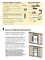
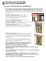
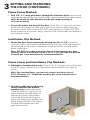
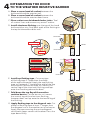
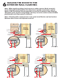
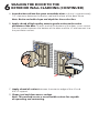
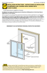
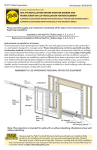
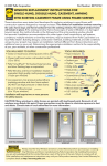
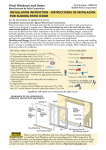
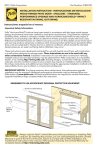
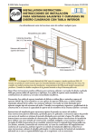
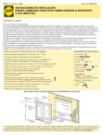
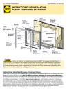
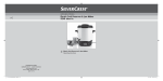
© 2011 Pella Corporation
Part Number: 818T0101
INSTALLATION INSTRUCTION –
SINGLE PANEL, SINGLE PANEL WITH SIDELIGHT
COMBINATION AND 20 MINUTE FIRE RATED
WOOD FRAME ENTRY DOOR
Installation Instructions for Typical Wood Frame Construction.
These instructions were developed and tested for use with typical wood frame wall
construction in a wall system designed to manage water. These instructions are not
to be used with any other construction method. Installation instructions for use
with other construction methods may be obtained from Pella Corporation, a local
Pella retailer or by visiting http://www.pella.com. Building designs, construction
methods, building materials, and site conditions unique to your project may require an
installation method different from these instructions and additional care. Determining
the appropriate installation method is the responsibility of you, your architect, or
construction professional.
REMEMBER TO USE APPROPRIATE
PERSONAL PROTECTIVE EQUIPMENT.
Side
Flashing
Tape
Top
Flashing
Tape
Weather
Resistive
Barrier
Sheathing
Framing
Sill Support
Sill Flashing Tape #1
Sill Flashing Tape #2
Always read the Pella® Limited Warranty before purchasing or
installing Pella products. By installing this product, you are acknowledging that this
Limited Warranty is part of the terms of the sale. Failure to comply with all Pella
installation and maintenance instructions may void your Pella product warranty. See
Limited Warranty for complete details at http://warranty.pella.com.
YOU WILL NEED TO SUPPLY:
TOOLS REQUIRED:
Ř Composite/impervious shims/spacers (12 to 20)
Ř Tape measure
Ř #8 x 3" corrosion resistant woodscrews
Ř Level
Ř 16d galvanized finish nails or exterior grade
finish screws
Ř Square
Ř Pella foil backed butyl window and door flashing
tape or equivalent
Ř Drill with 1/8" and 3/16" drill bits
Ř Closed cell foam backer rod/sealant backer
(17 to 21 ft.)
Ř Great Stuff™ Window and Door Insulating Foam
Sealant by the Dow Chemical Company or
equivalent low pressure polyurethane window
and door foam - DO NOT use high pressure or
latex foams.
Ř High quality exterior grade polyurethane sealant
(2 to 3 tubes per door)
SEALANT
SEALANT
Ř Pella aluminum sill support or 2 x 4 wood blocking
Ř Stapler
Ř Scissors or utility knife
Ř #2 & #3 Phillips screwdrivers
Ř Hammer
Ř Caulking gun
Ř Putty knife
Ř Interior trim and/or jamb extensions (15 to 40 ft.)
Ř Aluminum head flashing
Ř Installation Clips (Optional)
1
ROUGH OPENING PREPARATION
A. Confirm the opening is plumb and level.
Note: It is critical the bottom is level.
B. Determine the finished floor height. If the
finished floor height will be more than 1"
higher than the surface the door will be set
on, add a filler board under the sill. The top
of the filler board should be within 1" of the
finished floor height.
C. Confirm the door will fit in the opening.
Measure all four sides of the opening to
make sure it is 3/4" larger than the door in
width and 1/2" larger in height. Measure the
opening width in several places to ensure
the studs are not bowed.
Note: 1-1/2" or more of solid wood
blocking (studs) is required around the
perimeter of the opening. Check the
wall for plumb and the opening for
square by checking opening diagonal
measurements. Fix any problems with the
rough opening before proceeding.
Interio
r
1A
1A
Interio
r
1C
1C
1
ROUGH OPENING PREPARATION
(CONTINUED)
D. Cut the weather resistive barrier, if applicable (1D).
1D
1D
Water Resistive Barrier
1st cut
3rd cut
4th cut:
Make a 6" cut up from
each top corner at a 45°
angle to allow the weather
barrier to be lapped over
the fin at the head of
the door.
2nd cut
E. Fold the weather resistive barrier (1E). Fold side
flaps into the opening and staple to inside wall. Fold
top flap up and temporarily fasten with flashing tape.
1E
1E
F. Apply sill flashing tape #1. Cut a piece of
flashing tape 12" longer than the opening width.
Apply at the bottom of the opening as shown (1F)
so it overhangs 1" to the exterior.
Note: The tape is cut 12" longer than the width
so it will extend 6" up each side
of the opening.
G. Tab the sill flashing tape and fold. Cut 1" wide
tabs at each corner (1/2" from each side of corner)
(1G). Fold tape to the exterior and press firmly to
adhere it to the weather resistive barrier.
H. Apply sill flashing tape #2. Cut a piece of
flashing tape 12" longer than the opening width.
Apply at the bottom further towards the interior,
overlapping tape #1 by at least 1". Do not allow the
tape to extend past the interior face of the framing
(1H). If the wall depth is greater than 5", add a
third piece of flashing tape. The flashing tape
should come to within 1" of the interior face of the
framing.
1"
1F
6"
"
1/2/2"
1
1G
1"
1G
1H
1H
Note: The flashing tape does not need to extend
all the way to the interior of the framing.
I. When required for adequate sill support,
attach the optional aluminum sill support or wood
blocking to the exterior of the box plate to support
the exterior edge of the door sill (1I). Place the sill
support flush with the sill rough opening.
1I
2
PREPARE THE DOOR FOR INSTALLATION
TWO OR MORE PEOPLE WILL BE REQUIRED TO HANDLE
THE PANEL AND FRAME SAFELY.
A. Remove plastic wrap and cardboard packaging from door. DO NOT remove
plastic shipping spacers. The shipping spacers will help keep the door square
during installation. DO NOT open the door until it is fully fastened.
If Attaching with fasteners through the Brickmould go to Step 3
Anchoring Method – (Installation Clip or Frame Screw Through Frame)
B. Doors using Installation Clips: Install installation clips. Place each clip so
the lip is facing up and against the brickmould at the locations shown in the
placement diagram. Secure each clip by driving a #6 x 5/8" corrosion resistant
screw through each of the outer two holes of the three holes shown.
Note: If clips are to be bent; pre-bend before attaching to frame.
#6 x 5/8" corrosion
resistant screws
Lip
2B
C. Doors using Frame Screws: Open door panels; drill and counter-sink 3/16"
diameter clearance holes through the door frame jambs, (head and sill of
sidelight units) but not into the rough opening at the locations shown. Where
applicable, clearance holes are drilled though open hinge screw holes and
each strike hole.
Pilot Hole
Pilot Hole
Pilot Hole
Alternative Pilot Hole
for Screw Install
Alternative Pilot Hole
for Screw Install
Pilot Hole
Pilot Hole
Pilot Hole
DOOR UNIT, JAMB TO JAMB
SIDELIGHT UNIT, HEAD TO SILL
SIDELIGHT UNIT, JAMB TO JAMB
2
PREPARE THE DOOR FOR INSTALLATION
Anchor Spacing for Single Units:
Ř 2 – #10 x 2-1/2" screws at each hinge
Ř 2 – #10 x 2-1/2" screws at each strike
Ř #10 x 3" screw or clip directly across from each hinge
Ř #10 x 3" screw or clip 6" from each corner on 81-1/2" entry door frames only
(not sidelights) interacting with the rough opening
Ř #10 x 3" screw or clips as indicated on 97-1/2" entry door frames
Anchor Spacing for Combination Units:
Ř 2 – #10 x 3" screws at each sidelight head and sill
Ř #10 x 3" screw or clip at other indicated locations
Ř 2 - #10 x 2-1/2" screws at each hinge
Ř 2 - #10 x 2-1/2" screws at each strike
Diagrams for placement of installation clips or frame screw clearance
holes for 6'8" and 8' height doors and single doors with sidelights.
3"
3"
6"
2B
6" 6"
2B
9-1/4"
2B
6"
2B
81-1/2"
81-1/2"
2C
21"
2B
2C
2C
2C
21"
21"
2C
9-1/4"
6" 6"
3"
3"
= Screw or clip location other than at hinge or strike.
3"
3"
6-3/4"
21"
2B
2B
2B
21"
97-1/2"
97-1/2"
21"
2C
2C
21"
6-3/4"
3"
3"
2C
3
SETTING AND FASTENING THE DOOR
A. If unit is equipped with a screw type pre-hanging plug for transporting,
remove the screw portion from the exterior of the jamb before setting the door.
Note: If a brickmould/exterior trim is being added to the door, install and
seal it to the frame at this time. Align the inside of the brickmould/exterior
trim with the end of the sill.
Pre-Hanging Plug:
Leave in place until unit is
temporarily fastened.
Pre-Hanging Plug Screw:
Remove before installation.
B. Place three 3/8" beads of sealant long the bottom of the opening. Place the
first bead approximately 3/4" from the exterior of the rough opening. Continue
the first two beads up 6" onto each jamb of the rough opening. (3B). Place the
second bead so it is 1/2 from the interior surface of the door sill. Place a third
sealant bead in the sill support groove of 1/4" from the exterior edge of the
wood blocking.
1"
2
3"
4
2B
3B
1"
4
TWO OR MORE PEOPLE WILL BE REQUIRED FOR THE FOLLOWING STEPS
C. Apply sealant to the entire bottom surface of
brickmould to help prevent moisture absorption.
Apply sealant to the back side of brickmould
around the entire perimeter of the door unit that will
seal the brickmould to the wall.
3C
3
SETTING AND FASTENING
THE DOOR (CONTINUED)
Fasteners Through Brickmould Method:
D. Insert the door from the exterior of the building. DO NOT slide the bottom
of the door into the opening (2D). (Sliding will damage the sealant lines.)
Place the bottom of the door at the bottom of the opening, then tilt the top into
position. Center the door between the sides of the opening to allow clearance
for shimming.
For doors with brickmould, drive a 16d
galvanized finish nail or an exterior grade finish
screw through the brickmould in each upper
corner to secure the door.
#16 galvanized
finishing nails
2D
3D
For doors with NO brickmould, Follow frame
screw or installation clip method.
Frame Screw Method: Insert one #8 x 3" screw into the
top anchor hole on each side of the frame.
2C
3D
Installation Clip Method: Insert one screw into one
hole in each of the top clips. These are used to hold the
door in place while shimming it plumb and square.
E. Plumb and Square Door. Shim unit in place by driving
in shims from the interior. Shim behind each hinge, at
each screw or clip location, and behind the dead bolt
lockstrike. Keep shims back 1/2" from the interior face of
the door frame.
2D
3E
Use a level to plumb the hinge side jamb both ways
(right to left and inside to outside) and check for square.
Make any necessary adjustments.
Note: It may be necessary to use additional fasteners
for the applicable fastening method to maintain
plumb in the inside to outside orientation.
Fasteners Through the Brickmould: Use 16d
galvanized nails or exterior grade finish screw as needed through
the brickmould.
Frame Screw Method: Insert additional screws as required through
the installation holes.
Installation Clip Method: Insert additional screws as required
through the holes in the installation clips frame to maintain plumb
in the inside to outside orientation.
Note: DO NOT over shim. (DO NOT bow the jamb inward.)
3
SETTING AND FASTENING
THE DOOR (CONTINUED)
INCORRECT
F. Carefully open the door and remove all
shipping spacers. Remove pre-hang plug
from the bore hole. Carefully open and close
the door.
CORRECT
2G
3F
Check for even contact between the door
panel and weatherstrip on both jambs and
across the head. (3H) If space exists between
weatherstrip and door panel at top, move the
bottom of the lock side out. If space appears
at the bottom, move the top lock side out.
Note: By design the hinge side reveal of
the door will be closer to the jamb than the lock side.
G. Pre-drill with 3/16" bit through the door frame at each open hinge screw
hole (not into wall framing) and drive screws (provided) through each hole
in the hinge leafs, through the shims and into the wall or sidelight. Pre-drill
with 3/16" bit through the frame (not into the wall framing) behind the
weatherstripping at each remaining hinge side location as well as at each lock
jamb shim location (and also through the holes in the lock and if applicable
in the dead bolt strike) Drive #8 x 2-1/2" screws through each lock jamb shim
and into the wall or sidelight. Screw heads must be driven flush with door
frame to avoid interference with door operation.
Interior
Interior
3G
2G
2G
3G
H. Check door operation. Open and close the door to check for proper operation.
Note: If there are any problems with the operation, recheck and adjust the
reveal by adjusting the shims.
I. Fasteners through brickmould method: Place and set additional 16d
galvanized finish nails or exterior grade finish screws through the brickmould to
achieve a final spacing of approximately 4" from ends and 24" O.C. Countersink
all fasteners and cover with exterior grade putty.
3
SETTING AND FASTENING
THE DOOR (CONTINUED)
Frame Screw Method:
J. Drill 1/8" x 1" deep pilot holes through the clearance holes and into the
rough opening framing in the head, jambs, and threshold of the door frame.
Note: Be certain to shim between jambs and rough opening at
all screw locations.
K. Secure the jambs and head of the door. Drive #10 x 3" corrosion resistant
wood screws through the door frame and shim, into the rough opening.
Drive the screws until snug but DO NOT over-tighten the screws. DO NOT
bend or bow the unit frame. Apply sealant to the screw heads not located at
the hinges or strikes.
Installation Clip Method:
L. Fasten the door to the opening by driving two #8 x 1-1/4" corrosion
resistant screws into the pre-punched holes in the clips. If the clips are bent
and fastened to the interior stud/block, install the screws as close to the
bend as possible.
Note: DO NOT shim above the door. For masonry openings use two
masonry screws a minimum size of 3/16" x 1-1/2" per clip. Pre-drill the
masonry per screw manufacturer’s recommendations.
Frame Screw and Installation Clip Methods:
M. Sidelights of combinations only: Drive # 10 x 3" through each of the holes
in the sill. Apply sealant to the screw heads not located at the hinges or
strikes.
Note: For concrete floors, use masonry screw a minimum size of
3/16" diameter x 3". Predrill the masonry per screw manufacturer’s
recommendations.
N. Check for sufficient weatherstrip
contact between the bottom
weatherstrip and the threshold.
Close the door on a dollar bill or
sheet of paper located above an
adjustment screw; light friction
should be felt when pulling the
paper out indicating a good seal is
being made. If there is not, adjust
the threshold. Repeat for each
adjustment screw.
3N
3
SETTING AND FASTENING
THE DOOR (CONTINUED)
O. If needed, the height of the threshold can be
adjusted to achieve appropriate contact with
the door sweep. Remove screw cover caps as
necessary and use a #3 Phillips screwdriver to
turn the adjustment screws clockwise to lower
the threshold or counter-clockwise to raise the
threshold.
3O
P. Place a 1/4" bead of sealant along the corners
where the sill meets both side jambs.
Q. Before the sealant sets up; remove paper
backing from the corner seal pad and position the
pad embedded in the sealant and tight against the top of
the adjustable threshold, with the thin portion of the pad
flush with the interior face of the jamb (both jambs).
Interior
R. Install handle and lock hardware. Refer to manufacturer’s
instructions included with the hardware.
Note: At this time, install any additional fasteners if
needed to meet local code requirements such as those
required to comply with the Florida Building Code.
Remove paper
backing from the
corner seal pad
3P
Exterior
3Q
S. Apply 1/4" bead of sealant where each sidelight jamb meets the
sidelight sill and around the exterior mullion cover where the door and
sidelight frame are joined together.
3S
3S
Front View
4
INTEGRATING THE DOOR
TO THE WEATHER RESISTIVE BARRIER
A. Place a corner bead of sealant between the
brickmould and the exterior wall.
Exterio
r
B. Place a corner bead of sealant between the
brickmould and the exterior door frame.
C. Place sealant over brickmould miter joints. Tool
all sealant lines and remove any excess sealant.
3A
4A
D. Install aluminum flashing over the top of the head
brickmould or trim. Seal both ends of the flashing to
the top brickmould and the wall.
SEALANT
3A
4A
3D
Head Flashing
HEAD
3B
4D
4B
3B
SEALANT
Sealant
Flashing Tape
4D
SEALANT
3A
4A
Head Flashing
3C
4E
JAMB
4E
3B
SEALANT
E. Install top flashing tape. Cut one piece
of flashing tape 2" wider than the width
of the top brickmould. Apply the top flashing
tape so it extends 1" beyond the end of the top
brickmould. Position the tape so it covers the
vertical leg of the aluminum flashing and laps
onto the sheathing above the door.
4F
3E
F. Fold down the top flap of the weather
resistive barrier. Cut the barrier so it covers
the vertical leg of the aluminum flashing,
however does not lap onto the horizontal leg of
the flashing.
G. Apply flashing tape to the diagonal cuts. Cut
pieces of flashing tape at least 1" longer than
the diagonal cut in the weather resistive barrier.
Apply the tape covering the entire diagonal
cut at both upper corners of the door. Press the
tape down firmly.
3F
4G
5
INTERIOR SEAL
Caution: Ensure use of low pressure polyurethane window and
door installation foams and strictly follow the foam manufacturer’s
recommendations for application. Use of high pressure foams or improper
application of the foam may cause the door to bow and hinder operation.
A. Apply insulating foam. From the interior, insert the nozzle of the applicator
approximately 1" deep into the space between the door and the rough
opening and apply a 1" deep bead of foam. This will allow room for
expansion of the foam and will minimize squeeze out. Apply sealant across
the interior surface of shims to create a continuous seal. Follow foam
manufacturer's instructions. For doors with jamb extensions installed, ensure
the foam is placed between the door frame and the and the rough opening,
not between the jamb extension and the rough opening.
Note: DO NOT apply foam to the lower 6" of each jamb. (see 5D).
Note: DO NOT completely fill the space from the back of the brickmould
to the interior face of the opening.
Note: You may need to cut excess foam out of the lock strike.
B. Check the door operation by opening and closing the door.
Note: If the door does not operate correctly, check to make sure it is still
plumb, level, square and the sides are not bowed. If adjustments are
required, remove the foam with a serrated knife. Adjust the shims and
reapply the insulating foam sealant.
4A
5C
C. Add a sealant bead across the inner sill
and 6" up each jamb between the frame
and rough opening and tie in with the
foam sealant application.
Interio
r
4D
5C
6"
D. Apply interior trim as desired.
Note: Use backer rod between the frame jamb and opening 6" up each
jamb in accordance with sealant manufacturer's instructions.
6
SEALING THE DOOR TO THE
EXTERIOR WALL CLADDING
Note: When applying siding, brick veneer or other exterior finish materials,
leave adequate space between the door frame and the material for sealant.
Refer to the illustration that corresponds to your finish material. Not allowing
adequate space and not using backer rod may cause the sealant to break down
prematurely and allow water to infiltrate.
Note: If brickmould or exterior trim is not used, install backer rod and sealant
between door frame and adjacent material.
BRICK
VENEER
Sealant
typical
3/8"
Clearance
Sealant
typical
3/8"
Clearance
WOOD
SIDING
with TRIM
Insulate and
seal per Step 4
Insulate and
seal per Step 4
3/8"
3/8"
1/2"
Min.
Sealant
typical
3/8"
Clearance
Insulate and
seal per Step 4
3/8"
1/2"
Min.
WOOD
SIDING
Sealant
typical
3/8"
Clearance
Insulate and
seal per Step 4
3/8"
1/2"
Min.
1/2"
Min.
VINYL/STEEL
SIDING
6
SEALING THE DOOR TO THE
EXTERIOR WALL CLADDING (CONTINUED)
A. Insert backer rod into the space around the door so there is approximately
1/2" clearance between the backer rod and the face of the door frame.
Note: Backer rod adds shape and depth for the sealant line.
B. Apply a bead of high quality exterior grade sealant to the entire
perimeter of the door. At each end of the bottom of the door, insert sealant
into the spaces between the bottom of the door and the sill and connect it to
the perimeter sealant.
5B
6B
5A
6A
C. Apply a bead of sealant between the exterior edge of the sill and
the sill support.
D. Shape, tool and clean excess sealant.
Note: This method creates a more flexible sealant line capable
of expanding and contracting.
FINISHING INSTRUCTIONS
Paint or finish immediately after installation.
Note: DO NOT paint, stain or finish weather strip or vinyl parts!
If paint, stain or finish gets on the weather stripping, wipe it
off immediately with a damp cloth. To maintain proper product
performance, do not remove weather strip, foam corner seal wedges
or gaskets. Air and water leakage may result if these factory-installed
items are removed. After finishing, allow doors to dry completely
before closing them. Pella will not be responsible for finishing
imperfections. The use of unapproved finishes, solvents or cleaning
chemicals may cause adverse reactions with door materials. Pella will
not be responsible for problems caused by the use of unapproved
materials. If in doubt, contact your local retailer or representative.
Use of inappropriate finishes, solvents, brickwash or cleaning chemicals will cause
adverse actions with window and door materials and voids the Limited Warranty.
Care and maintenance information is available in the Pella Owner’s Manual.
You can obtain an owner’s manual by contacting your local Pella retailer. This
information is also available on www.pella.com.
Factory Prefinished Panels: A door panel that has been prefinished with stain or
paint from the factory requires no additional finishing. Clean the surface with mild
soap and water. DO NOT use abrasives. DO NOT scrape or use tools that might
damage the surface.
Clad Exterior Frame:
The exterior frame is protected by aluminum cladding with our tough
EnduraClad® baked-on-factory finish that needs no painting. Clean this surface
with mild soap and water. DO NOT use abrasives. DO NOT scrape or use tools
that might damage the surface.
Panel Cleaning and Prep Instructions for Unfinished or Primed Panels:
Dry wipe dust from doors gently. Examine door for possible smudges or
fingerprints made from normal handling or construction. To remove smudges,
lightly wipe surface with warm water. DO NOT sand surface of fiberglass panel.
Scuff sand with light grade sand paper or abrasive pad (220 grit or higher). Rinse
surface with mineral spirits for fiberglass panels and warm water for steel panels.
Let door and sidelight surfaces dry completely before applying finish. Finish the
door panels as soon as possible after installation.
Staining fiberglass panels or unfinished interior frame members:
Fiberglass door and sidelight panels may be stained with a gel stain if a wood look
is desired. Pella offers stain kits in a variety of colors. Apply and finish per the stain
kit manufacturer’s instruction. Ensure that all exposed panel edges are finished to
minimize the chance of damage. Unprimed interior frame parts may be stained
with wood stains and should be finished with a minimum of two coats of a clear
polyurethane finish. DO NOT bridge the top coat between the outer edge of the
glazing frame and the door panel.
Note: The fiberglass base color tone will vary. This variance is normal
and will not impact the stain color of the door.
FINISHING INSTRUCTIONS (CONTINUED)
Painting Instructions:
Wood door frame exteriors, premium steel door panels, sidelights are factory
primed. If a paint finish is desired, finish
the parts with two coats of a 100% latex paint that has a good blocking resistance.
On units with glass, do not bridge paint between the outer edges of the glazing
frame and the door panel. On fiberglass products, brush the paint in the same
direction as the simulated wood grain. Ensure that all exposed panel edges are
finished to minimize the chance of panel damage.
Failure to use the correct type of finish may result in a door that sticks shut. Ask a
qualified paint professional to specify a product with good blocking resistance.
IMPORTANT NOTICE
Because all construction must anticipate some water infiltration, it is important that
the wall system be designed and constructed to properly manage moisture. Pella
Corporation is not responsible for claims or damages caused by anticipated and
unanticipated water infiltration; deficiencies in building design, construction and
maintenance; failure to install Pella products in accordance with Pella’s installation
instructions; or the use of Pella products in wall systems which do not allow for
proper management of moisture within the wall systems. The determination of the
suitability of all building components, including the use of Pella products, as well
as the design and installation of flashing and sealing systems are the responsibility
of the Buyer or User, the architect, contractor, installer, or other construction
professional and are not the responsibility of Pella.
Pella products should not be used in barrier wall systems which do not allow for
proper management of moisture within the wall systems, such as barrier Exterior
Insulation and Finish Systems, (EIFS) (also known as synthetic stucco) or other nonwater managed systems. Except in the states of California, New Mexico, Arizona,
Nevada, Utah, and Colorado, Pella makes no warranty of any kind on and
assumes no responsibility for Pella windows and doors installed in barrier
wall systems. In the states listed above, the installation of Pella Products in
barrier wall or similar systems must be in accordance with Pella’s installation
instructions.
Product modifications that are not approved by Pella Corporation will void the
Limited Warranty.