1
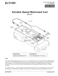
Includes Teacher's Notes and Typical Experiment Results Instruction Manual and Experiment Guide for the PASCO scientific Model ME-6694 012-06339A 7/97 TORSION PENDULUM © 1997 PASCO scientific $7.50 ® better 10101 Foothills Blvd. • P.O. Box 619011 • Roseville, CA 95678-9011 USA Phone (916) 786-3800 • FAX (916) 786-8905 • web: www.pasco.com ways to teach science Torsion Pendulum 012–06339A 012–06339A Torsion Pendulum Table of Contents Section Page Copyright, Warranty, and Equipment Return ................................................................ ii Introduction ...................................................................................................................1 Equipment .....................................................................................................................1 Assembly with the Rotary Motion Sensor .................................................................. 23 Suggested Experiment ...................................................................................................4 Experiment Experiment 1: Determining of the Magnitude of the Moment of Inertia (I) Using Two Methods .............................................................................. 512 Part A: Determining the Spring Constants of the Wires (κ) ............... 68 Part B: Determining the Moment of Inertia (I) of a Disk Using Two Methods ...................................................................................... 910 Part C: Determining the Moment of Inertia (I) of a Disk and Cylinder Using Two Methods ................................................................. 1112 Teachers Notes ............................................................ 1316 Technical Support ........................................................................................ Back Cover i Copyright, Warranty, and Equipment Return PleaseFeel free to duplicate this manual subject to the copyright restrictions below. Copyright Notice The PASCO scientific 012-06339A manual is copyrighted and all rights reserved. However, permission is granted to non-profit educational institutions for reproduction of any part of the Torsion Pendulum manual providing the reproductions are used only for their laboratories and are not sold for profit. Reproduction under any other circumstances, without the written consent of PASCO scientific, is prohibited. Limited Warranty PASCO scientific warrants the product to be free from defects in materials and workmanship for a period of one year from the date of shipment to the customer. PASCO will repair or replace at its option any part of the product which is deemed to be defective in material or workmanship. The warranty does not cover damage to the product caused by abuse or improper use. Determination of whether a product failure is the result of a manufacturing defect or improper use by the customer shall be made solely by PASCO scientific. Responsibility for the return of equipment for warranty repair belongs to the customer. Equipment must be properly packed to prevent damage and shipped postage or freight prepaid. (Damage caused by improper packing of the equipment for return shipment will not be covered by the warranty.) Shipping costs for returning the equipment after repair will be paid by PASCO scientific. Credits Author: Sunny Bishop ii Equipment Return Should the product have to be returned to PASCO scientific for any reason, notify PASCO scientific by letter, phone, or fax BEFORE returning the product. Upon notification, the return authorization and shipping instructions will be promptly issued. NOTE: NO EQUIPMENT WILL BE ACCEPTED FOR RETURN WITHOUT AN AUTHORIZATION FROM PASCO. ä When returning equipment for repair, the units must be packed properly. Carriers will not accept responsibility for damage caused by improper packing. To be certain the unit will not be damaged in shipment, observe the following rules: ➀ The packing carton must be strong enough for the item shipped. ➁ Make certain there are at least two inches of packing material between any point on the apparatus and the inside walls of the carton. ➂ Make certain that the packing material cannot shift in the box or become compressed, allowing the instrument come in contact with the packing carton. Address: Phone: FAX: email: web: PASCO scientific 10101 Foothills Blvd. P.O. Box 619011 Roseville, CA 95678-9011 (916) 786-3800 (916) 786-3292 [email protected] www.pasco.com 012–06339A Torsion Pendulum Introduction The PASCO ME-6694 Torsion Pendulum, an accessory for the PASCO CI-6538 Rotary Motion Sensor (RMS), facilitates the study of torque and the moment of inertia in a rotating body. The apparatus uses the data acquisition capabilities of the RMS with Science WorkshopTM through the PASCO 500 or 700 computer interfaces. Using the Torsion Pendulum, students can collect experimental data on rotational acceleration, rotational position, and rotational velocity for a variety experiments with the PASCO CI-6691 Mini-Rotational Accessory. Three wires with different diameters supplied with the Torsion Pendulum provide three different and repeatable torque magnitudes. Equipment 18-inch wires, 3 each: diameters (inches): 0.032, 0.047, 0.063 upper wire clamp lower wire clamp upper wire clamp thumbscrew and washer 18-inch wires lower wire clamp Additional Equipment Required: Science WorkshopTM version 2.1 or higher PASCO Computer Interface (500 or 700) computer Rotary Motion Sensor (CI-6538) Mini-Rotational Accessory (CI-6691) Force Sensor (CI-6537) Additional Equipment Suggested Table Clamp (ME-9376B) or Large Rod Stand (ME-8735) Support Rod (90 cm) (ME-8738) Safety Note: Always wear safety glasses when experimenting with the Torsion Pendulum. ä Replacement Wires To order a set of wires, call PASCO (800-772-8700) and order part number 003-06354. 1 Torsion Pendulum ä Note: You will need bend the wires as illustrated in Figure 1. (The direction of the bend is not critical. 012–06339A Assembly with the Rotary Motion Sensor (RMS) 1. Use the Table Clamp to secure the Support Rod to a table in close proximity to your computer interface (Figure 2). RMS to computer interface upper wire clamp wire with bent ends Figure 1 Bend the ends of the wires to 90° angles. lower wire clamp Support Rod Table Clamp upper wire clamp grooves Figure 2 Assembly of the Torsion Pendulum and the Rotary Motion Sensor 2. Slip the lower wire clamp onto the Support Rod. wire 3. Clamp the RMS at the top of the Support Rod. 4. Clamp one end of the wire under the washer of the upper wire clamp by firmly tightening the thumbscrew, being sure to seat the wire in the grooves (Figure 3). Figure 3 Securing the wire to the upper wire clamp 2 012–06339A Torsion Pendulum 5. Clamp the other end of the wire under the washer of the lower wire clamp by tightening the thumbscrew firmly. Be sure that the elbow of the bend in the wire fits snugly against the axle of the thumbscrew (Figures 4a and 4b). a Support Rod thumbscrew and washer b thumbscrew and washer wire wire lower wire clamp (front view) lower wire clamp (side view) Figure 4 Lateral (a) and front (b) views of attaching the bent wire to the lower clamp. 6. Adjust the height of the lower wire clamp to about 18 inches below the shaft of the RMS. 7. Align the guide of the upper wire clamp with the slot of the shaft of the RMS. Slide the upper wire clamp onto the shaft (Figure 4). 8. Adjust height of the lower wire clamp as necessary to position to top of the upper wire clamp approximately half-way up the shaft (Figure 5). 9. If necessary, adjust the lower wire clamp so the wire is perpendicular to the table. 10. Recheck all screws on the clamps to be sure each part is firmly secured. slot shaft of RMS guide upper wire clamp Support Rod Figure 5 Sliding the upper wire clamp onto the shaft of the Rotary Motion Sensor 3 Torsion Pendulum 012–06339A ➤ Note: The manual has been written with the assumption that the user has a basic familiarity with Science Workshop and has access to the Users Guide for Science Workshop. Users can gain basic skills with Science Workshop by viewing the training video and by doing the tutorial within Science Workshop. Another useful resource is the Quick Reference Card for Science Workshop. Suggested Experiment The following experiment will help students build skills in using the Torsion Pendulum using Science Workshop for data acquisition. Students may want to experiment further with varying lengths, thickness, or composition of wire, or with effects of variations of temperature on the torsional spring constant, κ. 4 012–06339A Torsion Pendulum Experiment 1. Determining the Magnitude of the Moment of Inertia (I) Using Two Methods Purpose The purpose of the experiment is compare the magnitude of the moment of inertia (I) of a disk and cylinder calculated by (1) using a torsional spring constant (κ) and the period of oscillation of the Torsion Pendulum (T) and (2) with I calculated using mass and radius measurements. Materials and Equipment Required • • • • • • Torsion Pendulum (ME-6694) Rotary Motion Sensor (CI-6538) Mini-Rotational Accessory (CI-6691) Science Workshop 2.1 or higher PASCO computer interface (500 or 700) computer • • • • • • • Force Sensor (CI-6537) Table Clamp (ME-9376B) Support Rod (90 cm) (ME-8738) mass balance metric ruler sturdy, non-stretching string—18 inches pages 2 and 3 of the manual Theory The magnitude of the moment of inertia (I) of a disk can be determined with the Torsion Pendulum using the following relationship: 2 T I= κ 2π where T= the time (s) for a period of oscillation of the Torsion Pendulum and κ = the torsional spring constant of the wire. The magnitude of the moment of inertia of a disk can also be determined by measuring the mass (m) and radius (R) of the disk and using the relationship: 1 2 I = mR 2 Therefore, in the case of a uniform disk rotating about its cylinder axis, the following relationship can be shown: 2 T 1 2 mR = κ 2 2π In the case of a disk plus a cylinder (Part C of the experiment), the following relationship can be demonstrated: 2 T 1 2 1 2 2 κ = mR + m(R1 + R2 ) 2 2 2π where R1= the inner radius of the cylinder and R2 = the outer radius of the cylinder. 5 Torsion Pendulum 012–06339A Part A: Determining the Torsional Spring Constants of the Wires (k) Set Up the Equipment 1. Assemble the Torsion Pendulum and the RMS as directed on pages 2 and 3 of the manual, using the 0.032 inch (diameter) wire. 2. Securely tie the Force Sensor to the large pulley of the 3-step pulley on the RMS with a piece of sturdy string 0.5 m in length. Set Up Science Workshop 1. Plug the digital plugs of the RMS into digital channels 1 & 2 on the computer interface box. 2. Plug the DIN connector of the Force Sensor into analog channel 1 of the computer interface box. 3. Turn on the interface box and start Science Workshop. 4. In the Setup Window, set up the RMS on digital channels 1 & 2 and the Force Sensor on analog channel 1. ➤ Note: Refer to the RMS and Force Sensor manuals for more detailed instructions on setting them up in Science Workshop. 5. Double-click the Force Sensor icon and set the sensitivity to Med (10X). 6. Click the Sampling Options button and set the sampling rate to 50/s. 7. Click and drag a Graph icon to the Force Sensor icon. Click the Statistics button and select Curve Fit > Linear Fit from the pop-up menu. Size and move the Graph display as is convenient. 8. Double-click the RMS icon and set Divisions/Rotation to 1440. 9. Click the x-axis input button ( Angular Position (angPos) 6 ) on the Graph display and select Digital (This will set the input for the x-axis). 1> 012–06339A Torsion Pendulum Collect the Data 1. Put your safety glasses on. 2. Wind the string around the large pulley in a clockwise direction. a Force Sensor 90° T AR E b 90° Figure 1.1 Hold the Force Sensor 90° to the pulley (a) and 90° to the support rod (b). 3. Hold the Force Sensor parallel to the table at the height of large pulley and prepare to pull it straight out (Figure 1.1). 4. Start recording data and pull the Force Sensor straight out until about 5 N of force is exerted. 5. Stop recording data (This will be Run 1). 6. Change the wire to the 0.47 inch diameter wire. 7. Repeat steps 2-5 (Run 2). 8. Change the wire to the 0.62 inch diameter wire. 9. Repeat steps 2-5 (Run 3). Save the file. 7 Torsion Pendulum 012–06339A Analyze the Data 1. Use the following formula to calculate the torsional spring constant (κ) for each wire and record in Table 1.1: F κ= θ where l = the length of the lever arm in meters (the distance from the axis of the pulley to the groove of the pulley) and F = force in expressed in newtons, and θ ιn the angular displacement at a force F. Table 1.1 Calculation of torsional spring constants of the wires (κ) 8 Run wire diameter (inches) 1 0.032 2 0.047 3 0.062 slope of F vs. angPos (m) κ (N·m) ä Note: Click the Autoscale button on each Graph display if necessary. 012–06339A Torsion Pendulum Part B: Determining the Moment of Inertia (I) of a Disk Using Two Methods Set Up Science Workshop 1. Use the setup detailed in Part A. Save As a different file name, and delete all data sets (Runs 1 - 3) and the Graph display. (Note: The Force Sensor will not be used in Parts B and C.) 2. Click the Sampling Options button and set the sampling rate to 200 Hz. 3. Click and drag a Graph display to the RMS icon and choose Angular Pos) from the pop-up menu. (This will set input for the y-axis.) Position (ang Set Up the Equipment 1. Attach the disk from the Mini-Rotational Accessory to the 3-step pulley with the thumbscrew (Figure 1.2). 2. Check the thumbscrews holding the wire to be sure they are tight. disk from Mini-Rotational Accessory 3-step pulley Collect the Data 1. Put your safety glasses on. 2. Twist the disk 1/4 turn clockwise. 3. Begin recording data, release the disk, and record for about 3 5 seconds. 4. Stop recording data. 5. Click on the Autoscale button to resize the graph, if necessary. 6. Use the Smart Cursor to determine the time for each period of oscillation (T) of the pendulum (measure the time between adjacent maxima of the angular position vs. time graph). Record in Table 1.2. 7. Change the wire to the 0.047 inch diameter wire and repeat steps 26. Figure 1.2 Experimental setup 9 Torsion Pendulum 012–06339A 8. Change the wire to the 0.062 inch diameter wire and repeat steps 26. 9. Determine the mass and radius of the disk and record below. mass of disk (kg)_________ radius of disk (m)_________ Table 1.2 Calculation of I from torsional spring constants of wires (κ) Run wire diameter (inches) 1 0.032 2 0.047 3 0.062 κ (N·m) (from pt.A) T (s) I (kg/m2) I (using mass and radius measurements) _____________ Compare the values of calculated I 2 1. Calculate I using both formulas: above. 10 T I= κ 2π and I= 1 2 mR 2 and record 012–06339A Torsion Pendulum Part C: Determining the Moment of Inertia (I) of a Disk and Cylinder Using Two Methods 1. Place the ring of the Mini-Rotational Accessory on the disk (Figure 1.3). 2. Repeat steps 26 of Part B. Record your data in Table 1.3. cylinder from MiniRotational Accessory disk from MiniRotational Accessory 3-step pulley 3. Change the wire to the 0.047 inch diameter wire and repeat steps 26. 4. Change the wire to the 0.032 inch diameter wire and repeat steps 26. 5. Measure the mass and R1 and R2 of the cylinder and record below. Figure 1.3 Experimental setup for Part C mass of cylinder (kg) ____________ R1 (m) ____________________ R2 (m) ____________________ Table 1.3 Calculation of Idisk and cylinder from the torsional spring constants of wires (κ) wire diameter (inches) κ (N·m) (from part A) T (s) I disk and cylinder (kg/m2) 0.032 0.047 0.062 Idisk and cylinder (using mass and radius measurements) _____________ R2 Compare the values of calculated I 1. Calculate I using both formulas: R1 2 T I= κ 2π and and record above. 1 2 1 2 2 I = mR + m(R1 + R2 ) 2 2 1 2 2 I = m(R1 + R2 ) 2 11 Torsion Pendulum Questions 1. How closely did the calculations of I match? 2. What are some possible sources of experimental error? 12 012–06339A 012–06339A Torsion Pendulum Teachers Notes: General ➤ Safety Note: Pendulum Use safety glasses when operating the Torsion 0 Experimental data will vary somewhat from the typical data included here due to the differences in wire lengths and other variables, but the overall data patterns will be the same. slope of the fitted line -6.0 Run #6 Force (N) -4.0 -2.0 Linear Fit y = a1 + a2 x a1 = -0.16328 a2 = -1.42996 chi^2 = 0.03058 iterations = 20 0 1.0 2.0 3.0 4.0 Run #6 Angular Position (rad) 5.0 6.0 Figure TN1.1 Typical data for determining the torsional spring constant (κ) (0.047 inch diameter wire) Table TN1.1 Calculation of torsional spring constants of the wires (κ), typical data κ (N·m) Run wire diameter (inches) slope of F vs. angPos l (m) 1 0.032 -0.3162 0.0254 0.008 2 0.047 -1.4300 0.0254 0.036 3 0.062 -4.4465 0.0254 0.113 13 Torsion Pendulum 012–06339A Run #1, 2, 3 Angular Position (rad) -4.0 -3.0 -2.0 -1.0 0 1.0 Part B 0.062 in. wire 0.047 in. wire -5.0 0.032 in. wire 2.5 3.0 3.5 4.0 4.5 5.0 5.5 Time (s) Figure TN1.2 Typical data for determining the period of rotation (T) for the three wire diameters (disk accessory) Table TN1.2 Calculation of I from torsional spring constants (κ) of wires Run wire diameter (inches) κ* (N·m) T (s) I (kg/m2) 1 0.032 0.008 0.861 1.5 x 10⁻⁴ 2 0.047 0.036 0.408 1.5 x 10⁻⁴ 3 0.062 0.113 0.239 1.6 x 10⁻⁴ *from part A I (using mass and radius measurements) 1.4 x 10 -4 14 mass of disk 0.126 kg* radius of disk 0.047 m* *may vary somewhat 012–06339A Torsion Pendulum -5.0 Run #4, 5, 6 Angular Position (rad) -4.0 -3.0 -2.0 -1.0 0 1.0 Part C 0.032 in. wire 0.062 in. wire 0 0.5 1.0 0.047 in. wire 1.5 2.0 2.5 3.0 3.5 Time (s) Figure TN1.3 Typical data for determining the period of rotation (T) for the three wire diameters (disk plus cylinder) Table TN1.3 Calculation of I disk plus cylinder from torsional spring constants (κ) of wires Run wire diameter (inches) κ* (N·m) T (s) I (kg/m2) 1 0.032 0.008 1.826 6.8 x 10 2 0.047 0.036 0.861 6.8 x 10⁻⁴ 3 0.062 0.113 0.500 7.2 x 10⁻⁴ -4 mass of cylinder 0.468 kg* R1 of cylinder 0.027 m* R2 of cylinder 0.039 m* *may vary somewhat *from part A I disk plus cylinder(using mass and radius measurements) 6.7 x 10 -4 kg/m2 I = 1.4 x 10⁻⁴ kg/m2 (disk)** + 5.3 x 10⁻⁴ kg/m2 (cylinder) I = 6.7 x 10⁻⁴ kg/m2 **from Part B 15 Torsion Pendulum 012–06339A Questions 1. The experiment demonstrated that the magnitude of the moment of inertia of a disk can be determined two ways: using the torsional spring constant of a wire (κ) and the period of 2 T κ and by oscillation of the Torsion Pendulum (T), applying the relationship I = 2π 1 2 measuring the mass and diameter of the disk and applying the relationship I = mR . 2 2. The calculated magnitude of I is approximately the same using either method. However, some experimental error is to be expected, particularly since some portions contributing to I (the pulley, axle, etc.) were not included in the calculation of I from using mass and radius measurements, but were included in the calculation of I using the torsional spring constant of the wire and period of oscillation of the Torsion Pendulum. The same comments apply to Part C. 16 012–06339A Torsion Pendulum Technical Support Feedback Contacting Technical Support If you have any comments about the product or manual, please let us know. If you have any suggestions on alternate experiments or find a problem in the manual, please tell us. PASCO appreciates any customer feedback. Your input helps us evaluate and improve our product. To Reach PASCO For technical support, call us at 1-800-772-8700 (toll-free within the U.S.) or (916) 786-3800. fax: (916) 786-3292 e-mail: [email protected] web: www.pasco.com Before you call the PASCO Technical Support staff, it would be helpful to prepare the following information: ➤ If your problem is with the PASCO apparatus, note: Title and model number (usually listed on the label); Approximate age of apparatus; A detailed description of the problem/sequence of events (in case you cant call PASCO right away, you wont lose valuable data); If possible, have the apparatus within reach when calling to facilitate description of individual parts. ➤ If your problem relates to the instruction manual, note: Part number and revision (listed by month and year on the front cover); Have the manual at hand to discuss your questions. 17