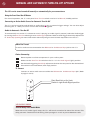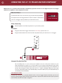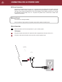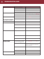
1
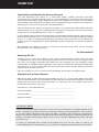
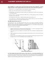
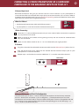
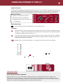
JC 1 Amplifier
Owner’s Guide
THANK YOU!
1
Congratulations and Thank You for Choosing Parasound
Your new Parasound Halo Series JC 1 mono block power amplifier represents the latest
advancements in amplifier technology. The JC 1 was designed by CTC builders and it uses higher
quality parts and achieves higher performance than any amplifier we’ve made since Parasound
was founded in 1981. We’re proud to offer you this exceptional audio component, knowing that it
will bring you many years of enjoyment and dependability.
Here at Parasound, we design our products to perform at a higher level of flexibility and sonic
performance than you may have expected. We encourage you to read this entire manual to learn
all the features and capabilities of your new JC 1 Amplifier.
If you’re eager to get up and running right away, simply follow the basic step-by-step instructions
to connect and operate the JC 1. If you want to learn more about the technical and design aspects
of your JC 1, refer to the Technically Speaking and Design Overview sections in the back of the
manual. If you run into difficulties, the Troubleshooting Chart should help you quickly remedy the
problem.
We appreciate you taking the time to read these instructions and thank you for selecting
Parasound for your listening pleasure.
The Parasound Staff
Unpacking Your JC 1
Unpack your JC 1 from the shipping carton, remove the enclosed AC power cord, the small
“L” shaped metal rack mounts, and the gray control wire with a sub-mini 2.5 mm plug on each
end. (This is the trigger connection wire). While you are unpacking your new amplifier, inspect
it thoroughly for possible shipping damage. If you see any, contact your Parasound dealer right
away. Be sure to save and store both the inner and outer cartons and the packing inserts for
possible future transport. To save
room for storage, you can cut the seams on the bottom of the cartons and flatten them.
Keeping Records for Future Reference
Record the serial number located on the bottom of your JC 1 in the space below. Also note
your Parasound Dealer’s name and phone number. We recommend that you keep your purchase
receipt with this manual and store them both in a safe place. You may need to refer to this
information sometime in the future.
Parasound JC 1 Amplifier Serial #: ____________________________________
Parasound Dealer: ___________________________________________________
Phone Number______________________________________________________
Date of Purchase: ___________________________________________________
YOU SHOULD KNOW
There is no Parasound warranty for this unit if it was not purchased from an Authorized Parasound
Dealer. Investigate any claims of warranty coverage made by unauthorized dealers very carefully
as you will need to depend entirely upon the dealer, and NOT upon Parasound. Unauthorized
dealers may lack the capability to arrange repairs of Parasound equipment. Authorized Parasound
Dealers are listed at www.parasound.com or you can call 415-397-7100 between 8:30 am and 4:30
pm Pacific time.
A missing or tampered serial number could indicate that this unit was stolen or sold by an
unauthorized dealer. You should return it to your dealer immediately for replacement or a full refund.
TABLE OF CONTENTS
JC 1 Amplifier
PLACEMENT GUIDELINES FOR YOUR JC 1
1
_________________________________________________________________________________
CONNECTING A STEREO PREAMPLIFIER OR A SURROUND
2
CONTROLLER TO THE BALANCED INPUT ON YOUR JC 1
_________________________________________________________________________________
CONNECTING A STEREO PREAMPLIFIER OR A SURROUND
3
CONTROLLER TO THE UNBALANCED INPUT ON YOUR JC 1
_________________________________________________________________________________
4
CONNECTING A SPEAKER TO YOUR JC 1
_________________________________________________________________________________
5
MANUAL AND AUTOMATIC TURN ON-OFF OPTIONS
_________________________________________________________________________________
6
CONNECTING AN EXTERNAL DC SOURCE FOR AUTOMATIC TURN ON-OFF
_________________________________________________________________________________
7
CONNECTING THE JC 1 TO TRIGGER ANOTHER COMPONENT
_________________________________________________________________________________
8
UNDERSTANDING THE INDICATORS ON THE JC 1
_________________________________________________________________________________
9
CONNECTING THE AC POWER CORD
_________________________________________________________________________________
10
MAINTAINING YOUR JC 1
_________________________________________________________________________________
11
TROUBLESHOOTING GUIDE
_________________________________________________________________________________
12
SERVICING YOUR JC 1
_________________________________________________________________________________
13
TECHNICALLY SPEAKING
_________________________________________________________________________________
15
PARASOUND JC 1 DESIGN OVERVIEW
_________________________________________________________________________________
17
PARASOUND JC 1 SPECIFICATIONS
_________________________________________________________________________________
1
1
PLACEMENT GUIDELINES FOR YOUR JC 1
Power amplifiers are usually heavier and generate more heat than other components. To avoid
damage to the JC 1 or other equipment and to reduce risk of fire, you must follow these guidelines:
•
Place the JC 1 on a separate shelf that will adequately support its weight.
•
Keep it away from heat sources such as air ducts or radiators.
•
Avoid placing it on carpeting or another material that might obstruct airflow into the openings
in the chassis bottom.
•
Leave at least 3” of space around both sides and 6” of space above the top. The bottom
clearance can be a little less.
•
Do not block the front of the JC 1 behind closed cabinet doors during use.
•
Do not stack the JC 1 with other components inside a cabinet unless you use a fan to circulate
and exhaust the warm air that builds up between them.
Rack Mounting Your Parasound JC 1
To mount the JC 1 into a 19” wide equipment rack, you must first attach its Rack Mount Adapters
(provided). With its four feet removed, the JC 1 chassis and front panel height occupies four rack
spaces (7” or 176 mm). When mounting equipment below the JC 1, you will also need to allow
about 1/8” below the unit for the bottom chassis screws.
To attach the rack mount adaptors
•
Remove the three shiny screws from each side of the JC 1. These are arranged vertically,
behind its front panel and in front of its first heatsink fin.
•
The angled part of the brackets that attaches to the rack should be just behind the front
panel.
•
Line up the holes on each rack mount adaptor with the holes on the unit and reinsert the
three screws.
•
Make sure the screws holding the rack mounts are tight because they will support the entire
weight of the JC 1 when it’s installed into the equipment rack.
HRA-4
AdapterMounted
Mounted on
1
RackRack
Adapter
onJCJC
1
A single standard rack space allows 1-3/4” vertical inches in a 19-inch wide equipment rack.
This measurement standard was developed by the EIA (Electronic Industries Association) so
manufacturers of electronic components and equipment racks could build products in standardized
heights that would fit in a uniform space. Please call your Parasound dealer or Parasound Technical
Services if you need additional advice about rack mounting the JC 1.
CONNECTING A STEREO PREAMPLIFIER OR A SURROUND
CONTROLLER TO THE BALANCED INPUTS ON YOUR JC 1
Balanced Input Jack
Balanced connections will give you the best sound in most instances. If your preamplifier or
surround controller has balanced XLR output jacks, we recommend that you use them. Refer to
the Balanced and Unbalanced Lines in the Technically Speaking section for additional information
about why we recommend using balanced lines.
What You’ll Need:
• One balanced interconnect cable with XLR connectors
• A preamplifier or surround controller with balanced outputs
Before Connecting
Leave the JC 1’s AC cord disconnected until you have made all other connections to prevent
any surprise burst of sound.
Make sure that all your cables are long enough so they are not strained or stretched once
they are connected.
Make sure the Select switch on the JC 1 is in its Balanced Input (right) position.
To Connect
1
Plug the male end of the balanced interconnect cable into the Balanced Input jack on the JC 1.
2
Plug the female end of this cable into the desired channel balanced output jack on your
preamplifier or surround controller.
3 &4
Repeat steps 1 and 2 above to connect additional JC 1s to other controller channels.
COMPONENTS
OUTPUTS
Right
SURROUND
SOUND
CONTROLLER
or
Left
PREAMP
4
3
Auto Turn On
Delay
Seconds
Sensitivity
Input mV
None
4
12
8
20
50
200
100
< Select <
< Select <
<
12 Volt
Trigger
Manual
Audio
Signal
12V Input
Trigger
Output
YOU SHOULD KNOW
Balanced XLR Jacks and Their Pin Configuration
The balanced input on the JC 1 uses an XLR jack that conforms to the industry standard
of: Pin 1: Ground, Pin 2: Positive (+), Pin 3: Negative (--). The balanced outputs on some
components use terminals with 3 screws instead of XLR jacks. These are compatible with the
JC 1 as long as you match the bare wires to the corresponding pins on the XLR plug: + to
pin 2, - to pin 3, and Ground to pin 1.
2
3
CONNECTING A PREAMPLIFIER OR A SURROUND
CONTROLLER TO THE UNBALANCED INPUT ON YOUR JC 1
1
2
CONNECTING SPEAKERS TO YOUR JC 1
4
Speaker Terminals
The two five-way binding post speaker terminals on the JC 1 are connected in parallel and accept most
speaker wire terminations including single or dual banana plugs or 1/4” spade lugs. The openings in
the terminals are too small to accommodate bare ends of the gauge speaker wire you should use.
What You’ll Need:
Common Speaker Connectors
The GND notch
signifies ground
or speaker left
• Speaker wire (AWG 16 or thicker)
with banana plugs or spade lugs.
Red ususally
designates right
Stripped bare ends won't fit terminals.
•
Dual
Banana Plug
Α Loudspeaker
Single
Banana Plug
Spade Lug
Stripped
AWG wire
Before Connecting
Remove power to all the components in your audio system.
To Connect
1
Connect the wire with the ridge or other marking to either red + (positive) speaker terminal
on the JC 1. Connect the wire without the ridge or other marking to the corresponding black
-- (negative) speaker terminal on the JC 1.
2
Insert the other end of the wire with the ridge or other marking into the red + (positive)
terminal on the speaker. Insert the wire without the ridge or other marking into the black -(negative) terminal on the speaker.
3 &4
Repeat steps 1 and 2 with the other JC 1 speaker terminal to bi-wire your speaker.
Auto Turn On
Delay
Seconds
Sensitivity
Input mV
None
4
12
8
20
50
200
100
< Select <
< Select <
<
12 Volt
Trigger
Audio
Signal
Manual
12V Input
Trigger
Output
1
Speaker
2
YOU SHOULD KNOW
Correct Speaker Polarity is Important
Polarity refers to the + and - connections. Speaker wires are coded with printing or a ridge on the
insulation on one of the leads so you know which lead was connected to the + and - terminals at the
other end. This coding will help you keep the + and - polarity consistent for all channels. Refer to Speaker
Polarity in the Technically Speaking section for additional information.
5
MANUAL AND AUTOMATIC TURN ON-OFF OPTIONS
The JC 1 can be turned on and off manually or automatically for your convenience.
Using the Front Panel On-Off Button
For manual operation, the JC 1 rear panel Auto Turn On switch must be in its Manual (middle) position.
Connecting an Active Audio Source for Automatic Turn On-Off
The JC 1 can be turned on and off with an audio signal, or by an external trigger voltage. You can also adjust
how long the JC 1 delays its actual turn on after it’s been triggered.
Audio for Automatic Turn On-Off
To automatically turn on the JC 1 whenever music is playing (an audio signal is present), select the Audio trigger
by moving the Auto Turn On switch right to its Audio Signal position. Refer to Audio Trigger Sensitivity Adjustment
in Technically Speaking for more information about adjusting the level of audio required to turn the JC 1.
What You’ll need:
An active audio source connected to the Balanced or Unbalanced Input jack on the JC 1
Before Connecting
Remove power to all the components in your audio system.
Make sure the Auto Turn On switch on the JC 1 is in its Audio Signal (right) position.
Set the Audio triggering Sensitivity adjustment knob on the rear panel to the desired level.
Start with the 3 o’clock detent (click stop) position.
To Connect
Connect an active audio source to either the Balanced or Unbalanced Input jack. (Refer
to pages 2 and 3)
Auto Turn On
Delay
Seconds
Sensitivity
Input mV
None
4
12
8
Start Sensitivity at 3 o'clock
Switch in right Audio Signal position
20
50
200
100
< Select <
<
12 Volt
Trigger
Audio
Signal
Manual
12V Input
Trigger
Output
YOU SHOULD KNOW
Turn Off Delay in the Audio Mode
When the music (audio signal) stops, the JC 1 will remain turned on for about five minutes. This
delay prevents unwanted turn-off during silent passages in music or pauses between tracks.
If you want to automatically turn on the JC 1 with an external DC voltage, select the DC trigger by
moving the Auto Turn On switch on the rear panel left to its 12 Volt Trigger position.
What you’ll need:
A wire with a 2.5 mm sub-mini plug on each end (provided)
A “control” component with +9Vdc to +12 Vdc trigger voltage
Before Connecting
Remove power to all the components in your audio system.
Make sure the Auto Turn On switch on the rear panel is in its 12 Volt Trigger
7
CONNECTING THE JC 1 TO TRIGGER ANOTHER COMPONENT
Whenever the JC 1 is turned on either manually or automatically, it generates 12 Vdc at its 12 V Trigger Out jack so it can trigger
additional JC 1 amplifiers or other components on and off.
What You’ll Need:
A second wire with a 2.5 mm sub-mini plug on each end (not provided)
A component that can be triggered with an external +9 Vdc to +12 Vdc source.
(The JC 1 DC Trigger output provides up to 150 mA of current.)
2.5 mm sub-mini plug
Before Connecting
Remove power to all the components in your audio system.
To Connect
1
Plug one end of this trigger wire into the 12 V Output jack on the JC 1
2
Plug the other end of this wire into the component that you want the JC 1 to trigger.
Auto Turn On
Delay
Seconds
Sensitivity
Input mV
None
4
12
8
20
50
200
100
< Select <
<
12 Volt
Trigger
Audio
Signal
Manual
12V Input
Trigger
Output
1
2
Input
COMPONENT
TO POWER
Automatic Turn On Delay Time
You can delay the JC 1 turn on time so it doesn’t turn on at the same instant as your
other components (or other JC 1s). This avoids turn-on surges and brownouts that might
cause units with microprocessors to lock up, or even trip house wiring circuit breakers. If
you’re lucky enough to own more than one JC 1, select a different delay time for each
unit. Turn the Delay knob for the desired delay time from None (fully counterclockwise) to
12 Seconds (fully clockwise).
YOU SHOULD KNOW
If the device use your JC 1 controls doesn’t have a 2.5 mm trigger output connector, you can cut
one plug off the trigger wire and terminate the end as required. The lead with the stripe is positive
and the lead without the stripe is negative.
UNDERSTANDING THE INDICATORS AND CONTROLS ON THE JC 1
A
AC Present Indication
When the JC 1 is plugged into a live AC outlet, a soft blue halo glows behind its On-Off button and its
red “P” Badge glows faintly. These indicate that the JC 1 is plugged into a live AC outlet, even when it is
turned off.
B
On and Off Indications for Both Manual and Automatic Modes
When the JC 1 is first turned on, the soft blue glow behind its On-Off button turns red for about five
seconds and then becomes a brighter blue.
C
High-Temp Indicator
This indicator is near the right side of the panel recess. It will glow red if the JC 1 overheats.
D
Ground Switch
The Ground switch can assist in reducing audible hum caused by ground loops in your system. Leave
this switch in its Normal (right) position unless you hear hum through your speakers (you’ll only be able
to hear this hum after your entire system is installed and operating). You can try the Lift (left) position to
eliminate it. Refer to the Technically Speaking section for detailed technical information about the causes
of ground loops and what you can do about them.
E
Bias Level Switch
The Bias Level switch offers two bias setting for the output transistors. In its Low (left) position, extremely
generous bias idle current and class A operation make crossover and higher-order odd harmonic
distortion inaudible. In its High (right) switch position, bias idle current is increased to perfectly match
the characteristics of the JC 1s output devices. This all but banishes these distortions. With its Bias Level
switch set to High, the JC 1 will run quite warm and consume more AC power when it is idling or playing
at low listening levels. If your JC 1 is VERY well ventilated, you may find the high bias offers a sonic
improvement. If your JC 1 is mounted in a cabinet, or ventilation is restricted in any way, we recommend
you leave the Bias Level Switch in its Low position.
A
B
C
Auto Turn On
Delay
Seconds
Sensitivity
Input mV
None
4
12
8
20
50
200
100
< Select <
D
< Select <
<
12 Volt
Trigger
Audio
Signal
Manual
12V Input
Trigger
Output
8
9
CONNECTING THE AC POWER CORD
AC Power Connections
We recommend that you plug your JC 1 into the same AC wall outlet or power strip that
powers your other audio components, especially the preamplifier or system controller.
Having all the audio components on the same power circuit helps prevent hum caused
by possible ground loops. The JC 1 requires AC power that is continuous rather than
switched on and off.
What you’ll need:
An IEC 65 AC Cord (provided)
An AC outlet or high quality AC power strip within reach of the AC cord
Before Connecting
Remove power to all the components in your audio system.
To Connect
1
Plug the female end of the AC cord to the AC receptacle on the rear of the JC 1.
2
Plug the male end of the AC cord to an AC outlet or power strip.
J C 1 A m pl i f i er
Parasound Products. Inc.
San Franscisco, CA USA
Ground
Lift
Normal
Fuse
T15A/250V-115V Area
T8A/250V-230V Area
Power Consumption: 1200W
AC 115V
AC 230V
60Hz
50Hz
1
2
MAINTAINING YOUR PARASOUND JC 1
Your Parasound JC 1 power amplifier requires no periodic maintenance and has no userserviceable parts inside. To avoid the risk of electric shock, do not remove its top cover. The
amplifier’s exterior can easily be cleaned with a soft cloth pre-moistened only with a few drops
of water or glass cleaner.
Main Power Fuse
If this fuse blows, please contact Parasound Technical Service for further advice.
Notes:
10
11
TROUBLESHOOTING GUIDE
PROBABLE CAUSE
Power cord is disconnected
REMEDY
Check polarity of DC source with a voltmeter
Try connecting a 9 V battery to the 12V DC input
Make sure Auto On
JC 1 will not turn off when
audio signal is removed
Hum and / or buzz
through speakers
Ground loop between preamplifier
and JC 1 or at the equipment rack
Move the Ground Lift switch to its Lift position
Install nylon shoulder washers on both sides of
the panels of all equipment to insulate metal
from touching the rack
SERVICING YOUR JC 1
If All Else Fails-Call Us fo Help
Call your Parasound dealer or Parasound’s Technical Service Department toll free at 1-866-770-TECH
(8324) between 8am and 4pm Pacific Time. We can often solve the problem with simple diagnostic
tests you can perform yourself. If we determine that your JC 1 will need further inspection or
servicing, we will:
a) refer you to an authorized Parasound repair center near you, or
b) authorize return of the unit to us and advise you of the correct procedure.
Procedure for Returning Your JC 1 to Parasound for Service
If Parasound determines that you should send your JC 1 to Parasound, you will be given a Return
Authorization (RA) number. This RA number must be clearly marked on the outer carton only.
IMPORTANT: Enclose a copy of your original purchase receipt. A unit is eligible for warranty
repair ONLY when the purchase receipt shows that the unit was purchased from an Authorized
Parasound Dealer. A unit obtained through unauthorized channels is not eligible for warranty
repair. Parasound is not responsible for any sellers’ misrepresentations about our warranties or
other service policies.
We do not accept any of the following:
Units with collect shipping charges
Units without a valid RA number
Units without a suitable shipping carton
Units for which we see or hear evidence of improper packing
For a non-warranty repair, contact us for an estimate of the repair charges before you ship the unit
to us. The same packing and Return Authorization number procedures apply.
Important Notice - Shipping the JC 1
Before shipping the unit to Parasound, you MUST re-pack the unit into its fitted molded foam
insert sandwich and its original carton. If you do not have the original packing cartons and foam
inserts, call us for new packing materials that we can provide to you for a nominal charge. Use
of any other carton and packing materials will probably result in shipping damage, and refusal of
the unit. Common carriers such as UPS seldom pay claims for damage incurred during shipment
when a product is surrounded only with Styrofoam “peanuts” or otherwise improperly packed. We
cannot stress enough the importance of properly packing your JC 1. Shipping damage resulting
from inadequate packing can cost you a lot of money and significantly increase the time required
for repair. Ship the unit with adequate insurance. After repair under warranty, the unit will be
returned to you via prepaid UPS within the continental United States.
12
13
TECHNICALLY SPEAKING
Audio Trigger Sensitivity Adjustment
The Auto Turn On Audio Sensitivity Control sets the
threshold of the audio trigger signal. You can adjust
this level from a maximum sensitivity of 50 mV (fully
counterclockwise) to a minimum sensitivity of of 250
mV (fully clockwise). If you set this control to 50 mV,
the JC 1 might be falsely triggered on by non-musical
or noisy signals that can appear in the system, such as
when you switch preamp inputs at high volume levels.
If you set this control to 250 mV, the JC 1 might not
turn on during quiet musical passages. The detented
position (click stop) at 3 o’clock is a good starting point
and will be suitable in most systems.
the differential input “sees” a positive 1 Volt minus a
negative 1 Volt, or 2 Volts total. External hum and noise
that somehow gets into a balanced line is common to
both its positive and negative conductors with respect
to ground. Therefore, it is canceled or rejected by the
differential input circuit.
This phenomenon of rejecting noise signals common
to both positive and negative conductors is called
common-mode rejection. Differential inputs are
specified according to how well they reject signals
common to both conductors. This is measured in dB
and is called the common mode rejection ratio or
CMRR.
Balanced and Unbalanced Input Lines
Choosing Interconnect Cables and Speaker Wire
Recording and broadcast studios use balanced
connections exclusively because of their inherent
ability to reject noise and hum, thus assuring the best
sound. Certain high quality preamplifiers and surround
controllers built for residential use utilize balanced
connections with XLR jacks for the same reasons. All
Parasound Halo Series power amplifiers have balanced
inputs with XLR jacks so you can take full advantage of
their inherent noise reduction capability and superior
sound quality.
We are often asked to recommend specific brands of
interconnect cables and speaker wire. It’s true that
with some amplifiers, sound quality will vary greatly
according to interconnect cables and speaker wires.
However, Parasound amplifiers use robust circuitry
that sounds superb regardless of interconnects and
speaker wires. Therefore, we feel that choosing a brand
of cable for Parasound amplifiers is largely a matter of
personal taste.
Unbalanced connections with RCA jacks are found
on all home audio equipment. RCA jacks and twoconductor wires are less costly than the additional
circuitry, higher priced XLR connectors and threeconductor wiring required for balanced connections.
In an unbalanced line, the positive audio signal appears
at the center pin of the RCA jack and the negative
signal on the outer shield wire, which also functions
as the ground connection. Unbalanced interconnect
cables are vulnerable to hum from an AC line, or
other noise, such as RF (Radio Frequency), which
can be reproduced through your loudspeakers. Since
the unbalanced line’s ground also carries the audio
signal, there is no way for the connected amplifier or
preamplifier to distinguish between the audio signals
you want and unwanted noise emanating from external
sources.
Balanced lines are superior because they utilize
separate conductors for audio and ground: two inner
conductors carry the positive and negative audio
signal, and a third outer wire connects the grounds
and also shields the two signal conductors. When the
positive and negative signals appear at the component
receiving the signal they are equal, but 180 degrees
out of phase with each other with respect to ground.
To send and receive balanced signals requires special
differential circuitry.
A differential input circuit amplifies only the difference
between the positive and negative signals. For example,
when a 1 Volt signal arrives at a balanced input stage,
Signal Polarity
The JC 1 does not invert polarity. Therefore, if you
know that your preamplifier or surround controller
inverts polarity, you may connect your speaker + and opposite of the above instructions to reverse polarity.
This applies to all speakers in your system driven by
amplifiers that don’t invert polarity. Contact the maker
of your preamplifier or surround controller to verify its
polarity if this is not mentioned in its owner’s manual.
Speaker Wire Length and Gauge (thickness)
When selecting speaker wire, follow these guidelines:
• Keep the length of your speaker wire as short as
possible
• Use the thickest wire practical. For lengths greater
than 50 feet, use speaker wire with an AWG (gauge) of
14 or lower. The smaller the AWG, the thicker the wire.
•
Do not use speaker wire that is thinner than 16 AWG.
• Use the same length of speaker wire between each
JC 1 amplifier and speaker, regardless of the actual
distance between them.
TECHNICALLY SPEAKING continued
Eliminating Ground Loops - Hum and Buzz
Audible hum and buzzing noises in a system are usually
related to issues with the component grounds. Ground
(sometimes called common) is a point of reference for
voltages in virtually all audio and video components.
Ground is supposed to remain at zero volts while the
audio signal swings positive (voltage above ground)
and negative (voltage below ground). If ground isn’t
at zero, there can be an audible 60 Hz hum (or 50 Hz
hum in regions with 50 Hz AC). The harmonics of these
frequencies (120 Hz, 240 Hz, 480 Hz or 100 Hz, 200 Hz,
400 Hz) may add buzz in addition to the hum.
The ideal of zero voltage ground for all the components
in a system is practically impossible, because some
resistance between the ground points of different
components is inevitable. By keeping components
close together with their power cords plugged into
a common AC outlet or power strip, you’ll avoid the
problems created by resistance in the house’s wiring.
Hum and buzz is also caused when unwanted voltage
flows through multiple component ground points
called ground loops. Here are three tips to avoid ground
loops:
1. Use a balanced input line with your Parasound JC 1.
(See Balanced and Unbalanced Lines in this section).
2. When rack mounting, always use the included
insulated “shoulder” washers. These break the ground
loops caused by metal-to-metal contact between the
rack, the units, and their rack-mount bolts. Extras
are available from rack manufacturer Middle Atlantic
Products, www.middleatlantic.com.
3. Use the Ground switch on the JC 1 to eliminate most
ground loops. This separates the JC 1’s signal input
ground from its chassis ground to isolate unwanted
voltage in the ground shield of the unbalanced (RCA)
input cable. Be sure your system installation is finished
before you try moving the Ground Lift switch from its
“Normal” to its “Lift” position.
Level Control - Omitted by Design
There is no level (gain) control on the JC 1 to avoid
compromising the audio signal. We expect you’ll be
using a preamplifier or surround controller with a high
quality volume control and S/N ratio.
Two Sets of Binding Posts
The JC 1 is equipped with a second set of binding
posts to facilitate bi-wiring. This feature enables you to
“bi wire,” or connect two lengths of speaker cables to
the same speaker for improved performance. Refer to
the owner’s manual of your loudspeaker to determine
if the manufacturer recommends bi-wiring.
14
15
PARASOUND JC 1 DESIGN OVERVIEW
Designed by John Curl and CTC Builders
Complementary Configuration
Parasound has worked with legendary designer John
Curl since 1989. John has been a legend among
audiophiles and electronic engineers since the mid
‘70s. He pioneered measurements to correlate musical
accuracy with the materials used in component parts,
worked with world-class touring companies, and has
designed highly coveted audio classics. These designs
include the original Mark Levinson JC-2, Denneson
JC-80, Vendetta Phono Preamplifier, master recorders
for Wilson Audio and Mobile Fidelity; and the mixing
consoles used in live concerts by The Grateful Dead
and at the Montreux Jazz Festival in Switzerland.
Each stage of amplification has transistors fed by
the positive DC power supply and complementary
transistors fed by the negative DC power supply.
Thus, half of the devices amplify the positive half
of the musical waveform while the other half of the
devices amplify the negative half. This complementary
topology is inherently linear, and reduces distortion
and improves sonic accuracy.
In 2000 John formed CTC Builders to develop totally
uncompromised analog products. CTC’s products have
earned the utmost respect from the most discerning
audiophiles and high end magazine reviewers.
The Power Supply
The heart of the power supply is a 10 Ampere
(continuous!) toroid transformer, chosen for its
efficiency, low hum field, and high power rating.
Encapsulating this massive power transformer in an
epoxy-filled steel canister assures ultra-quiet
performance.
To create the high voltage B+ and B- supply rails for
the output stage, we use high-speed, fast-recovery
rectifier diodes and four enormous 33,000 uF Nichicon
"Gold Tune" series electrolytic filter capacitors, chosen
for their low Equivalent Series Resistance (ESR) and
dielectric absorption. In addition, these filter capacitors
are bypassed with smaller polypropylene capacitors
to reduce AC ripple in the DC supply and to further
eliminate noise and interference that is generated in
AC power lines from computers and other appliances
in the home.
Relay-Bypassed Soft Start Circuit
When the JC 1 is first turned on, there is a significant
amount of in-rush current to required to charge up
the enormous power supply capacitors. In order to
suppress this in-rush current and keep nuisance
tripping of circuit breakers, we employ NTC (negative
temperature coefficient) resistors. These resistors cut
the in-rush current by about 50%. Once they heat up,
they essentially become a jumper with zero ohms
resistance. However, the JC 1 goes one step further
for this circuit. After the NTC resistors have done their
job of suppressing in-rush current a gold contact relay
automatically is activated to jump across the NTC
resistors to completely bypass them. This extra step
insures that the resistors do not restrict any current
whatsoever to the power supply once the JC 1 is in full
operation.
The Input Stage
The JC 1’s input stage uses matched pairs of discrete
JFETs arranged in a differential configuration. JFETs
are ideal for the input stage because their inherently
high impedance is unaffected by the impedance of
source components. Differential configuration provides
superior noise reduction. These precision input JFETs
are also cascoded to produce the current necessary to
drive the MOSFET drivers in the following stage.
The Driver Stage
The driver stage provides critical amplification for which
we employ complementary matched pairs of MOSFETs
selected for their tube-like sonic qualities. MOSFETs
tend to generate less odd-order harmonic distortion
than bipolar transistors. This is important because
odd-order distortion sounds unnatural and fatiguing
to the human ear, whereas even-order distortion is
less offensive because it is consonant, rather than
dissonant. Our MOSFET driver stage prevents the
harshness and brittle sound so often found in other
amplifiers.
The B+ and B- power for our input and driver stage
cannot sag under load because it is supplied by
independent transformer secondary windings with
independent rectification, filtering, and voltage
regulation. This preserves soundstage width and depth
even when the JC 1 output stage is drawing enormous
current.
The Output Stage
The amplifier’s sonic characteristics are established by
its input and driver stages. Now, the sole job of its
output stage is to deliver the enormous current and
voltage from its power supply to the speakers. Bipolar
output transistors are better than MOSFETS in the
output stage because of their higher safe operating
area (SOA) and inherent ruggedness. The JC 1’s output
stage employs nine pairs of high current (15-ampere)
bipolar transistors to insure long-term reliability, even
with continuous high power operation and challenging
speaker loads. Lightning-fast (60 MHz) transistors
respond instantly to complex demands in the musical
signal, virtually eliminating distortions that occur with
slower transistors. Slew rate limiting and Transient
Intermodulation Distortion (TIM) are simply not an
issue in the JC 1.
PARASOUND JC 1 DESIGN OVERVIEW continued
Class A/AB Operation
Total Protection - Relays
Pure class A operation provides the purest sound.
However, an amplifier operating entirely in class A
operation would be enormous, highly inefficient, and
generate far too much heat. Class AB combines some
of the advantages of Class A with the efficiency of
Class B operation. It is a compromise that reduces the
heat generated in pure class A operation and the oddorder harmonic distortion created in class B. In class
AB, the driver and output stages are always turned
on, which provides a nominal amount of pure class A
operation. At higher power levels, when the musical
waveform swings from positive to negative and vice
versa, each bank of transistors is allowed to rest
momentarily. This resting, or quiescent time, makes
it possible to deliver high amounts of power without
overheating. It also makes it possible to use passive
cooling and avoid fans, whose noise can be heard
over the music. The JC 1 input and driver stages are
always on for 100% pure Class A while its output
stage provides up to 25 watts of pure Class A - more
than amplifiers selling for three or four times its price.
The result is less fatiguing, more natural sound at a
refreshing price.
The JC 1 has a high-quality protection relay with
gold-plated contacts for long-term reliability. This relay
functions to protect either the amplifier, the speaker,
or both. When the JC 1 is first powered on, the relay
remains open for three seconds as the positive and
negative power supplies stabilize and reach equilibrium.
This prevents annoying popping or other transient
noises. Relay protection also prevents speaker damage
in case of a catastrophic amplifier failure. Any amplifier
that doesn’t use relay protection for its speaker outputs
compromises the safety of the amplifier and your
speakers.
Total Protection - DC Servos
Total Protection - Fuses
Direct Current (DC) burns out speakers. Therefore,
every power amplifier must have some way to insure
that DC from its power supply never reaches its + or
- speaker terminals. Most amplifiers simply use trim
controls to reduce their DC offset or capacitors to block
DC. Unfortunately, trim controls can allow DC offset
to increase over time, and even the most expensive
capacitors in the audio signal path will “veil” sonic
clarity and attenuate bass response.
The JC 1 has separate fuses for its positive and
negative DC voltage rails. These fuses provide backup
protection in case the over-current protection does not
work in time, or if an internal part fails. In the event of
a part failure, these fuses halt operation to minimize
damage to additional parts.
Parasound power amplifiers incorporate ingenious
and fast-acting DC servo circuits, which completely
eliminate the need for coupling and blocking capacitors.
The JC 1 is direct-coupled from its input jack to its
speaker terminals. This advanced circuitry never needs
adjustment or maintenance. It operates outside the
audio signal path to keep the DC offset at the output of
the JC 1 at a constant 0.00 Vdc. The results are startling
clarity, freedom from listening fatigue, and formidable
bass response.
Total Protection - Current Overload
Specialized current-sensing transistors are connected
to the output stage of the JC 1 to constantly monitor
the current flow through the output transistors. If the
current drawn by this stage exceeds a predetermined
safe level due to a load impedance below 1 ohm or a
short circuit at the speaker terminals, the output relay
will open immediately to prevent the output transistors
or other parts from failing.
Chassis
The JC 1 chassis is heavy gauge steel with an aluminum
rear panel where its critical input circuit board mounts.
Aluminum is non-magnetic and cannot be energized
by nearby high voltage and current flow, thereby
removing a potential cause of “smearing” or other
audible intrusions.
16
17
PARASOUND JC 1 SPECIFICATIONS
Power Output. 20 Hz - 20 kHz
400 watts continuous, 8 Ω
800 watts continuous, 4 Ω
Input Sensitivity for 28.28 V Output into 8 Ω
Balanced: 1 V per leg
Unbalanced: 1 V
Class A Power Output
25 watts, bias set to High
10 watts, bias set to Low
Signal-to-Noise Ratio, input shorted
> 122 dB, IHF A-weighted, bias set to Low
> 120 dB, IHF A-weighted, bias set to High
> 113 dB, Unweighted, bias set to Low
> 111 dB, Unweighted, bias set to High
Current Capacity
135 amperes peak
Slew Rate
> 130 volts per microsecond
Frequency Response
2 Hz - 120 kHz, +0/-2 dB
Total Harmonic Distortion
< 0.15 % at full power
< 0.018 % at typical levels
IM Distortion
< 0.03 %
TIM
Unmeasureable
Dynamic Headroom
> 1.8 dB
Damping Factor
> 1200 at 20 Hz
Auto On DC Trigger Requirements
+9 Vdc to +12 Vdc, 2 mA
Auto On Audio Trigger Threshold
50 - 250 mV AC
Dimensions
Width: 17-1/2” (445 mm)
Panel height: 7” (178 mm)
Height with feet: 7-5/8” (194 mm)
Depth: 19-1/8” (485 mm)
Power Requirement
Standby: 25 watts
Idle: 250 watts
Full Power into 8 Ω: 1280 watts
Input Impedance
Balanced: 100 kΩ
Unbalanced: 50 kΩ
Net Weight
64 lb. (29.1 kg)
Features and specifications subject to change
without notice.
© Parasound Products, Inc., 2002.
v 1.1
Shipping Weight
78 lb. (35.5 kg)
Parasound Products, Inc. 950 Battery Street, San Francisco, CA 94111
415-397-7100 / Fax 415-397-0144 www.parasound.com