1
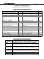
Optima 3600
Direct Vented
Top or Rear Vent
Gas Room Heater
For use with natural gas or propane*
WARNING: If the information in this manual is
not followed exactly, fire or explosion may result
causing property damage, personal injury or loss
of life.
Do not store or use gasoline or other flammable
vapors and liquids in the vicinity of this or any
other appliance.
USERS’ INSTALLATION
OPERATION AND
MAINTENANCE MANUAL
WHAT TO DO IF YOU SMELL GAS:
∗ Do not try to light any appliance.
∗ Do not touch any electrical switch; do not use
any phone in your building.
∗ Immediately call your gas supplier from a
neighbor’s phone. Follow the gas supplier’s
instructions.
∗ If you cannot reach your gas supplier, call the
fire department.
Installation and service must be performed by a
qualified installer, service agency or the gas
supplier.
This appliance may be installed in an
af t e rm a rk et
p e rm a n en t l y
l o c at ed,
manufactured home (USA only) or mobile
home, where not prohibited by local codes.
This appliance is only for use with the type
of gas indicated on the rating plate. This
appliance is not convertible for use with
other gases, unless a certified kit is used.
*Conversion kit required for Propane use
Installer: Please leave this manual with the appliance owner for future reference
7116 Beatty Dr
Mission, BC V2V 6B4
Canada
200-0217
DECEMBER 2005
INTRODUCTION
Thank you for purchasing the Optima 3600 Zero Clearance Direct Vented Fireplace
Gas Heater.
The Optima 3600 is one of the most advanced direct vented zero clearance gas
heaters on the market. It is designed using the latest technology and manufactured to
the highest quality.
Some of the many features are:
∗ True Zero Clearance
No standoffs required.
∗ Heater Classification
It is classified as a heating appliance. Therefore, it can be
operated continuously for zone heating.
∗ High Efficiency
It has high efficiency; therefore, less expensive to operate.
∗ Adjustable Flame
The flame aesthetics and heat output can be adjusted to suit
the owner’s moods and heating needs.
∗ Solid Construction
It is constructed mainly of satin coated, aluminized and
galvanized steel for long life and durability.
Please read the manual carefully prior to installation and operation of the
appliance. Proper installation, operation and maintenance of the appliance will
provide you with many years of enjoyment.
We recommend you record the following information:
Fireplace Model Number: ODV - 3600
Serial Number:
Date of Installation:
Type of Gas Used by the Fireplace:
Dealer’s Name & Address:
Dealer’s Phone Number:
Natural Gas
Propane
TABLE OF CONTENTS
Page
Caution & Safety Information
5
General Information
6
Appliance Dimensions
7
Installation Clearances
8
Electrical Connections, Fan System
9
Glass Door Removal
10
Log Placement
11
Installation Instructions
15
Optional Wall Switch or Thermostat
18
Top / Rear Vent Conversion
19
Allowable Termination Locations
20
Approved Vent Components
21
Venting Components - Parts List
22
Venting - Rear Vent
24
Venting - Top Vent
25
Horizontal Venting Instructions
26
Vertical Venting Instructions
27
Operation Instructions - Safety Information
28
Operation Instructions - Start Up & Shut Down Procedures
29
Maintenance
30
Troubleshooting
31
Servicing
33
Important Information
35
Replacement Parts List
36
Archgard Warranty
38
Warranty Registration Card
40
Optima 3600
5
CAUTION / SAFETY INFORMATION
Due to high temperatures, the appliance should be located out of traffic and away
from furniture and draperies.
Children and adults should be alerted to the hazards of high surface temperature
and stay away to avoid burns or clothing ignition.
Young children should be carefully supervised when they are in the same room as
the appliance.
Clothing or other flammable material should not be placed on or near the
appliance.
Any parts removed or opened for servicing of the appliance must be properly
replaced prior to operating the appliance.
The appliance must be inspected before use and at least annually by a qualified
service person. More frequent cleaning maybe required due to excessive lint from
carpeting, bedding material, etc. It is imperative that the control compartments,
burners and circulating air passageways for the appliance be kept clean.
Venting terminals shall not be recessed into a wall or siding.
This gas appliance must not be connected to a chimney flue serving a separate
solid fuel burning appliance.
FOR YOUR SAFETY - Do not install or operate your Archgard Optima 3600 Direct
Vent Gas Fireplace without reading and understanding this manual. Any
installation or operational deviation from this instruction manual voids the
Archgard Industries Warranty and may prove hazardous.
This appliance must be installed by a qualified gas installer and the installation
must conform to the installation codes.
Provide adequate clearance around air openings of the appliance.
Never obstruct front openings.
Provide adequate clearances for proper operation and servicing of the appliance.
This appliance must be properly connected to an approved venting system and
must not be connected to a chimney flue serving a separate solid fuel burning
appliance.
Optima 3600
6
GENERAL INFORMATION
APPLIANCE CERTIFICATION
This appliance is tested and certified to the following US and Canadian gas appliance standards.
- ANSI Z21.88b-2003 / CSA 2.33b-2003 Vented Gas Fireplace Heaters,
- CAN/CGA-2.17-M91 Gas-Fired Appliance fo Use at High Altitudes
Please contact Archgard Industries Ltd., if you have any questions regarding the certification of this
appliance.
INSTALLATION CODES
This appliance must be installed by a qualified gas appliance installer. The installation must conform with
the local codes or, in the absence of local codes, with the current National Fuel Gas Code, ANSI Z223.1/
NFPA 54, in the US or Installation Code, CSA-B149.1, in Canada. Electrical connections and grounding
must be in accordance with local codes, if any, if not, follow the current CAN/CSA C22.1 in Canada and
ANSI/NFPA 70 in the US. This appliance is certified for installation in a bedroom or a bedsitting room.
This appliance is only for use with the type of gas indicated on the rating plate and may be installed in an
aftermarket, permanently located, manufactured (mobile) home where not prohibited by local codes. See
owner’s manual for details. This appliance is not convertible for use with other gases, unless a certified kit
is used. This appliance must be installed in accordance with the current Standard CAN/CSA Z240 1411,
Mobile Housing, or with the Manufactured Home Construction and Safety Standard Title 24 CFR, Part
3280, or when such a standard is not applicable, ANSI/NCSBCS A225.1/NFPA 501A, Manufactured
Home Installations Standard. Only for direct discharge without duct connection. This appliance must be
direct vented using listed Simpson Dura-Vent components.
SPECIFICATIONS
Natural Gas (NG)
Propane (LP)
Manifold Pressure
1.7-3.5 in. W.C. (0.4-0.9 kpa)
6.5-10.0 in. W.C. (1.6-2.5kpa)
Min. Supply Pressure for
Purpose of Input Adjustment
4.5 in. W.C. (1.1 kPa)
11.0 in. W.C. (2.7 kPa)
Orifice Size
#43 DMS
#54 DMS
Nominal Input Rating
17,000 - 24,000 BTU/hr
(4.98 –7.03 kW)
19,000 -24,000 BTU/hr
(5.57 - 7.03 kW)
Altitude
0 - 4,500 ft. (0 - 1372 m)
0 - 4,500 ft. (0 - 1372 m)
Primary Air Opening
closed
25% open
HIGH ALTITUDE INSTALLATION
When installing this appliance beyond 4500 ft. (1372 m) above sea level, the appliance must be properly
de-rated and installed according to local codes, in the absence of local codes, with the current National
Fuel Gas Code, ANSI Z223.1/ NFPA 54, in the US or Installation Code, CSA-B149.1, in Canada.
Optima 3600
7
APPLIANCE DIMENSIONS
Optima 3600
8
INSTALLATION CLEARANCES
MANTLE & SIDEWALL CLEARANCES
CORNER FRAME DIMENSIONS
Mantle Height from Floor (B)
Mantle Depth (A)
40" (1016 mm)
12" (305 mm)
39" (991 mm)
10-5/16" (262 mm)
38" (965 mm)
8-9/16" (217 mm)
37" (940 mm)
6-7/8" (175 mm)
36" (914 mm)
5-1/8" (130 mm)
35" (889 mm)
3-7/16" (81 mm)
34" (864 mm)
1-11/16" (43 mm)
Sidewall clearance (C)
Unexposed Back & Sidewalls
Internal Ceiling
Floor
Mantle
Vertical Vent
Horizontal Vent
Horizontal Vent
= 6" (305 mm) from edge of unit
= 0"
= 40" (1016 mm) from floor
= 0"
= See Chart
= 1” (25 mm) to outside surface
= 1” (25 mm) to outside side and bottom surface
= 2” (50 mm) to outside top surface.
Note: Check local codes for floor requirements. This fireplace is suitable for installation
on a combustible surface.
Optima 3600
9
ELECTRICAL CONNECTIONS, FAN SYSTEM
WARNING: Before starting, make certain the power supply is turned OFF.
The Optima 3600 comes complete with a temperature activated fan and rheostat installed and
wired to an internal junction box. The heat sensor is factory set to close the circuit to the fan
speed control at 1100 F (430 C) and will turn off the fan when the temperature falls below 800 F
(270 C).
Have a qualified electrician run a 120VAC supply line to the lower right side of the fireplace
before installing the appliance. There should be 18” (460mm) of the supply line free for ease of
connection to the appliance. Connect the electrical supply line to the appliance at the same
time the gas line is being connected to the appliance.
NOTE: This appliance, when installed, must be electrically grounded in accordance with local
codes or, in the absence of local codes, with the National Electrical Code, ANSI/NFPA 70, or
the Canadian Electrical code, CSA C22.1.
Remove or open the bottom (louver) grill. Remove the junction box cover. Run the line into the
right side of the appliance through the hole in the rear of the junction box and hold with a
standard ⅞” (22 mm) clamp. Connect the (black) supply conductor to the free black conductor
from the speed controller with a marrette type wire connector. Connect the ‘neutral’ white
supply conductor to the free white conductor from the fan with a marrette-type wire connector.
Connect the ‘ground’ (green or bare) conductor to the ground screw in the junction box.
Replace the junction box cover. A BX connector or other suitable approved wiring strain relief
must be installed on the junction box.
WIRING DIAGRAM
SPEED
CONTROL
LINE
120 VAC
NEUTRAL
GROUND
LINE
NEUTRAL
GROUND
black
black
110ºF (43ºC) N.O.
THERMAL SNAP
SWITCH
white
black
CONVECTION BLOWER
white
green
To Appliance Body
SPEED
CONTROL
110ºF (43ºC) N.O.
THERMAL SNAP
SWITCH
MO
CONVECTION BLOWER
Optima 3600
10
GLASS DOOR REMOVAL
Removing the Glass Door
❖
❖
❖
❖
❖
❖
Remove the top & bottom louvers (or optional front).
Unhook the door latches found on the bottom of the firebox - shown below
Carefully lift and remove the door.
Place the door at a safe location where it cannot be scratched or damaged.
If the glass door is damaged, it must be replaced with another glass door certified for this
appliance.
Replacement glass doors are available through your Archgard dealer (See Replacement
Parts page 36)
Replacing the Glass Door
❖
❖
❖
❖
Check the condition of the glass and the gasket before installing door.
Carefully hook the door onto the 4 tabs on the top of the firebox. (2 left, 2 right)
Connect the door latches, at the bottom of the door, by pulling forward on the 2 bottom
latches and hooking them over the lower door frame flange.
Install the top & bottom louvers (or optional front).
If the glass has been damaged contact your dealer and replace the door assembly with a new
assembly provided by your dealer.
WARNING:
❖
❖
❖
Do not attempt to remove the glass door when the appliance is hot.
Do not abuse the glass door.
Do not strike or slam the glass.
TOP LATCH
BOTTOM LATCH
Optima 3600
11
LOG PLACEMENT
The Archgard pan burner and fiber logs are designed to give a realistic fire package, and are
created to maintain their appearance from the day they were originally installed. Care must be
given when first installing the logs and when removed for servicing, as they can be damaged or
broken if not handled properly.
After opening the log set package, inspect the logs to ensure that no damage has occurred
inside the package. Please report any damage immediately to your Authorized Archgard
Dealer.
Gas and vent connections must be made before installing the logs and embers on the pan
burner.
NOTE: Improper placement of logs may cause sooting on the internal parts and glass, and will
not be covered under warranty. Do not use broken or damaged logs.
WARNING: Failure to position the parts in accordance with these diagrams or failure to
use only parts specifically approved with this appliance may result in property damage or
Refer to the pictured instructions on the following pages that will show you how to correctly
place the logs. The bottom of each log has a code stamped on it that can be used as a reference to help locate the correct log.
IMPORTANT: Pins & holes must be aligned with logs & burner.
LOCATOR PINS ON BURNER SHOWN
LOCATOR PINS
Optima 3600
12
LOG PLACEMENT - CONTINUED
STEP 1 - PLACE REAR LOG (#146) ON PINS AND BURNER AS SHOWN
146
STEP 2 - PLACE LEFT LOG (#144) ON PIN AND LOG AS SHOWN
144
Optima 3600
13
LOG PLACEMENT - CONTINUED
STEP 3 - PLACE FRONT LOG (#147) ON PINS AND BURNER AS SHOWN
147
STEP 4 - PLACE RIGHT LOG (#145) ON PIN AND LOGS AS SHOWN
145
Optima 3600
14
LOG PLACEMENT - CONTINUED
STEP 5 - PLACE RIGHT LOG (#148) AND EMBERS AS SHOWN
148
146
144
145
147
STEP 6 - PLATINUM EMBERS SHOULD BE PLACED ON BURNER AS SHOWN
Optima 3600
15
INSTALLATION INSTRUCTIONS
PRECAUTIONS
❖
❖
❖
❖
❖
This appliance must be installed by a qualified gas installer and the installation conform to
the installation codes.
This appliance needs fresh air for safe operation and must be installed so there are
provisions for adequate ventilation air. Provide adequate clearance around air openings of
the appliance. Never obstruct front openings.
Provide adequate clearances for proper operation and servicing of the appliance.
This appliance must be properly connected to a venting system.
This appliance must NOT be connected to a chimney flue serving a solid-fuel appliance.
LOCATING GAS FIREPLACE
The venting system of this appliance must be installed in any location that is free of plumbing,
electrical wiring and heating or air conditioning ducts. Select a location that is accessible for
venting. See the ALLOWABLE TERMINATION LOCATIONS - page 20, in this manual. When
the appliance is installed directly on carpeting, vinyl tile or other combustible material, other than
wood flooring, the appliance must be installed on a metal or wood panel extending the full width
and depth of the appliance.
VENT TERMINATION LOCATION
1. Establish a suitable vent termination location. (See ALLOWABLE TERMINATION
LOCATIONS - page 20)
2. In heavy snowfall areas make sure vent termination is located where it can not be blocked by
snowfall or snow from snow removal equipment.
3. Locate vent termination away from plants, bushes or any other object on or near the vent
termination that will interfere or obstruct the air flow around it.
4. DO NOT recess vent termination into walls, sidings or planters.
5. Vent terminations located below 7 ft (2130 mm) from grade level or anywhere that it is a burn
hazard to the public, such as patios and balconies, must be protected with an approved
termination cage.
Optima 3600
16
INSTALLATION INSTRUCTIONS
GAS CONNECTIONS
Have your gas supplier or a qualified gas fitter run a gas supply line into the gas fireplace.
The line must be properly sized and fitted according to the installation codes. Upstream of
the supply connection, the fitter shall provide a manual shut-off valve.
CAUTION: The appliance and its individual shutoff valve must be disconnected from
the gas supply piping system during any pressure-testing of that system at test pressures
in excess of ½ psig (3.5 kPa). The appliance must be isolated from the gas supply piping
system by closing its individual manual shutoff valve during any pressure-testing of the
gas supply piping system at test pressures equal to or less than ½ psig (3.5 kPa). Failure
to do so will damage the appliance’s gas valve. Such damage is not cover by the
manufacturer’s warranty.
CHECKING INLET & OUTLET GAS PRESSURE
1. Open the lower grills.
2. The pressure test taps are located on the valve. The taps are located in the gas valve
front face. The inlet is marked ‘IN’ and the outlet is marked ‘OUT’. (See Fig.1)
3. Loosen the set screw inside the tap with a ⅛” (3 mm) wide flat screw driver.
4. Connect a ¼” (6 mm) rubber tube to the tap post and a manometer.
5. Verify the readings obtained are within specs (as shown on the appliance rating plate)
6. Be sure to tighten the set screw inside the tap after you are finish taking pressure
readings.
7. Check for leaks.
Fig.1
Optima 3600
17
INSTALLATION INSTRUCTIONS
GAS CONNECTIONS - CONTINUED
The minimum permissible gas supply pressure is 4.5 in. w.c. (1.12 kPa) for natural gas and 11.0 in. w.c.
(2.74 kPa) for propane. Maximum gas supply pressure should never exceed 14.0 in. w.c. (3.48 kPa) or ½
psi. for both natural gas and propane. BE SURE TO TIGHTEN THE PRESSURE TAP SET SCREW
AFTER CHECKING THE PRESSURE.
Before connecting the appliance to the gas supply line, double check that the appliance you have
purchased is designed for the gas type you are using. The gas type markings are located on the
certification label and also on the appliance’s gas valve.
Adequate clearance for proper installation and checking of the gas connections must be provided. All gas
connections must be checked for gas leaks.
CHECKING & ADJUSTING PILOT
The pilot flame should have the
characteristic as shown in the illustration
to the right. The flame should not have
yellow tips but should engulf the
thermocouple and thermopile. It can be
adjusted be turning the screw marked
“pilot” on the control valve.
Thermocouple
Electrode
Thermopile
Burner Ports
CONVERTIBLE PILOT ORIFICE
The pilot assembly is convertible to the
type of gas being used, simply unscrew
the body by using a 7/16” (11 mm)
wrench turn ¼open then push the small
metal tab across to the other side of the
body and retighten. Call your local
Authorized Archgard Dealer to
purchase the correct fuel conversion
kit for your gas appliance.
7/16” (11 mm)
WRENCH
(HERE)
AIR SHUTTER ADJUSTMENT
CAUTION: MUST BE DONE WHEN APPLIANCE IS COLD.
Remove / open lower louvre, slightly loosen the wing nut
located under the firebox near the centre at the rear. Push
back lever for cleaner burn; tab forward for a richer burn.
SHOWN FULLY CLOSED AND PROPERLY SET FOR
NATURAL GAS. PUSH BACK ¼ FOR PROPANE GAS.
Optima 3600
18
OPTIONAL WALL SWITCH OR THERMOSTAT
If a wall mounted switch or a wall mounted thermostat is desired, Archgard recommends that
the device be wired as shown in Fig 1. This will allow the original on/off rocker switch to be
used incase the device that is mounted to the wall is inoperable.
Note: Archgard Industries does not manufacture, or sell any wall switch or wall thermostat, and
will not extend warranty to them.
Thermostat / wall switch wire table
Recommended Maximum Lead Length
for two wires
Wire Size
Max. Length
14 GA.
50 Ft. (15.24 M)
16 GA.
32 Ft. (9.75 M)
18 GA.
20 Ft. (6.9 M)
20 GA.
12 Ft. (3.65 M)
22 GA.
9 Ft. (2.74 M)
VALVE CONNECTION for MILLIVOLT VALVE
Fig. 1
C
B
OPTIONAL REMOTE,
WALL SWITCH OR
WALL THERMOSTAT
D
ON / OFF SWITCH
A
WIRE TO
PIEZO
(SPARKER)
THERMOCOUPLE LEAD
B
THERMOPILE
C
PILOT CAP
D
THERMOCOUPLE
PI
LO
T
HI
LO
ELECTRODE
ON
A
OFF
PILOT ASSEMBLY
SUPPLY TUBE
CAUTION: DO NOT CONNECT ANY AC VOLTAGE TO THE GAS VALVE.
Optima 3600
19
TOP / REAR VENT CONVERSION
5
6
4
3
The appliance is easily converted from top vent
to rear vent.
The steps for converting are as follows:
1. Remove the top vent outer shell cover (#1)
1
2
3
2. Remove the top vent heat shield cover (#2)
3. Remove the outer collar assembly (#3)
4. Remove the exhaust collar assembly (#4)
5. Rotate the exhaust collar assembly and the
outer collar assembly to the rear vent
configuration and reinstall.
6. Install rear vent heat shield cover (#5)
7. Install rear vent outer shell cover (#6)
4
12 inches (30 cm)
21 inches from center of
termination (53 cm)
C= Clearance to permanently
closed window
D= Vertical clearance to
ventilated soffit located
above the terminal within a
horizontal distance of 2 feet
(61 cm) from the center line
of the terminal
3 feet (91 cm) within a
height 15 feet (4.5 m)
above the
meter/regulator assembly
H= Clearance to each side of
center line extended above
meter/regulator assembly
6 feet (183 cm)
12-3/4" to center of
termination (32 cm)
G= Clearance to inside corner
L= Clearance to service
regulator vent outlet
0"
F= Clearance to outside corner
21 inches from center
of termination (53 cm)
12 inches (30 cm)
B= Clearance to window or
door that may be opened
E= Clearance to unventilated soffit
12 inches (30 cm)
A= Clearance above grade,
veranda, porch, deck, or balcony
Canadian Installations
(1)
L= Clearance above paved
sidewalk or paved driveway
located on public property
K= Clearance to a mechanical
air supply inlet
J= Clearance to non-mechanical air
supply inlet to building or the
combustion air inlet o any other
appliance
12 inches (30 cm) ++
7 feet (2.13 m) +
6 feet (1.83 m)
12 inches (30 cm)
Canadian Installations (1)
*
*
3 feet (91 cm) above if
within 10 feet (3 m) horizontally
9 inches (23 cm)
US Installations (2)
*
21 inches from center (1) In accordance with the current CSA B149.1, National Gas and Propane Installation Code
of termination (53 cm) (2) In accordance with the current ANSI Z223.1/NFPA 54, National Fuel Gas Code
(+) A vent shall not terminate directly above a side walk or paved driveway that is located be0"
tween
two single family dwellings and serves both dwellings
12-3/4" to center of (++) Permitted only if veranda, porch, deck, or balcony is fully open on a minimum of two sides
beneath the floor.
termination (32 cm)
(*) For clearances not specified in ANSI Z223.1/NFPA 54 or CSA B149.1, “Clearances must
*
be in accordance with local installation codes and the requirements of the gas supplier.”
21 inches from center M= Clearance under veranda,
of termination (53 cm)
porch, deck, or balcony
12 inches (30 cm)
12 inches (30 cm)
12 inches (30 cm)
US Installations (2)
Optima 3600
20
ALLOWABLE TERMINATION LOCATIONS
Optima 3600
21
INSTALLATION INSTRUCTIONS
APPROVED VENT COMPONENTS
The appliance will not function without being connected to a proper venting system. This
appliance may only use direct vent system supplied by Archgard Industries or Simpson DuraVent direct vent systems with the appropriate adaptor dependent upon the venting guidelines
within this manual.
VENTING CONNECTION
For best and safe venting performance, here are some general venting rules:
❖
Use only Archgard, Simpson Dura-Vent, direct vent or Selkirk Direct Temp vent
components.
❖
Maintain a minimum of 1” (25mm) clearance to combustibles from the outside surfaces of
vertical vents and minimum of 1” (25mm) sides and bottom, and 2” (50mm) from top
surfaces of horizontal vents.
❖
Observe local code restrictions, if any, regarding the installation of this type of gas
appliance.
❖
Observe the venting charts given in this manual.
❖
Use vent spacers between the inside 4” (101mm) and outside 7” (178mm) vents at 3 ft
(915mm) intervals (Archgard Direct Vent System ONLY).
❖
Never slope horizontal vents downwards towards the vent termination.
❖
Terminate (Horizontally) the vent only with an approved vent termination supplied by
Archgard Industries (Part # TK-1) Simpson Dura-Vent Termination Cap or Selkirk direct
temp termination cap.
❖
Terminate (Vertically) the vent only with Simpson Dura-Vent Vertical Termination Cap or
Selkirk Direct Temp Vertical Termination Cap.
❖
Support horizontal vents every 3 ft (915mm) to prevent sagging.
Please strictly follow the venting instructions for optimum performance from the
appliance and to avoid sooting and/or service calls.
Optima 3600
22
VENTING COMPONENTS
SIMPSON DURA-VENT COMPONENTS
DESCRIPTION
PART #
DESCRIPTION
PART #
Horizontal Termination Kit
In Canada - Mandatory to add a wall thimble.
971
Vertical High Wind Termination Cap
(must be used for all vertical terminations)
991
Vertical Termination Kit
978
Horizontal. DV Termination with 1” return
984GL
6” Pipe Length - Black
908B
Horizontal. Square Termination Cap
984
9” Pipe Length - Black
907B
Horizontal. Square High Wind Termination Cap
985
12” Pipe Length - Black
906B
Snorkel-36” Rise Termination Cap
981
12” Pipe Length - Galvanized
906
Wall Thimble Cover Support Box
940
24” Pipe Length - Black
904B
Cathedral Ceiling Support Box
941
24” Pipe Length - Galvanized
904
Brass Trim fro Ceiling Support Box
3951
36” Pipe Length - Black
903B
Firestop Spacer
963
36” Pipe Length - Galvanized
903
Flashing 0/12 - 6/12
943
48” Pipe Length - Black
902B
Flashing 7/12 - 12/12
943S
48” Pipe Length - Galvanized
902
Storm Collar
953
11” - 14 ⅝” Adjustable Pipe Length - Black
911B
Vinyl Siding Standoff
950
17” - 24” Adjustable Pipe Length-Black
917B
Wall Strap
988
45° Elbow - Black
945B
Wall Pen Heat Shield (Wall Thimble)
942
45° Elbow - Galvanized
945
90° Elbow - Black
990B
45° Elbow - Swivel-Black
945BG
90° Elbow - Swivel-Galvanized
990G
45° Elbow - Swivel-Galvanized
945G
90° Elbow - Swivel-Black
990GB
90° Elbow - Galvanized
990
ARCHGARD VENTING COMPONENTS
PART #
DESCRIPTION
TVK-1
Archgard Flex Vent Kit with 36” (914 mm) vent length (includes TK-1)
TVK-2
Archgard Flex Vent Kit with 60” (1.52 M) vent length (includes TK-1)
TVK-10
Archgard Flex Vent Kit with 120” (3.05 M) vent length (includes TK-1)
TK-1
Archgard Horizontal termination head only
C-1
Archgard Safety Cage for Horizontal termination head (TK-1)
VSD-1
Archgard Vinyl siding deflector
SDA-U
Universal Flex, Simpson Dura-Vent Adapter
DV-GS
Simpson Dura-Vent venting system
SNK-24
24” Snorkel
Optima 3600
SELKIRK PARTS LIST
23
PART #
DESCRIPTION
4" x 6 5/8" LENGTHS
1604006
1604006B
1604009
1604009B
1604012
1604012B
1604018
1604018B
1604024
1604024B
1604036
1604036B
1604048
1604048B
1604082
1604082B
1604084
1604084B
4DT- 6
4DT- 6B
4DT- 9
4DT- 9B
4DT-12
4DT-12B
4DT-18
4DT-18B
4DT-24
4DT-24B
4DT-36
4DT-36B
4DT-48
4DT-48B
4DT-AJ12
4DT-AJ12B
4DT-AJ14
4DT-AJ14B
DIRECT-TEMP 6" PIPE LENGTH
DIRECT-TEMP 6" PIPE LENGTH BLACK
DIRECT-TEMP 9" PIPE LENGTH
DIRECT-TEMP 9" PIPE LENGTH BLACK
DIRECT-TEMP 12" PIPE LENGTH
DIRECT-TEMP 12" PIPE LENGTH BLACK
DIRECT-TEMP 18" PIPE LENGTH
DIRECT-TEMP 18" PIPE LENGTH BLACK
DIRECT-TEMP 24" PIPE LENGTH
DIRECT-TEMP 24" PIPE LENGTH BLACK
DIRECT-TEMP 36" PIPE LENGTH
DIRECT-TEMP 36" PIPE LENGTH BLACK
DIRECT-TEMP 48" PIPE LENGTH
DIRECT-TEMP 48" PIPE LENGTH BLACK
DIRECT-TEMP 12" ADJ PIPE LENGTH
DIRECT-TEMP 12" ADJ PIPE LENGTH BLACK
DIRECT-TEMP TELESCOPE ADJ LENGTH
DIRECT-TEMP TELESCOPE ADJ LEN BLACK
4DT-EL45
4DT-EL45B
4DT-EL90S
4DT-EL90SB
45 DEGREE ELBOW
45 DEGREE ELBOW BLACK
90S DEGREE ELBOW
90S DEGREE ELBOW BLACK
4DT-WTB
4DT-FS
4DT-TP
4DT-VS
WALL THIMBLE BLACK
FIRESTOP SPACER
TRIM PLATE BLACK
VINYL SIDING STANDOFF
4DT-CS
4DT-CCS
4DT-WS/B
4DT-OS
CEILING SUPPORT
CATHEDRAL SUPPORT BOX
WALL SUPPORT/BAND
OFFSET SUPPORT
4DT-VKC
4DT-HKA
4DT-HKB
4DT-VC
4DT-HC
4DT-SC
4DT-AF6
4DT-AF12
VERTICAL TERMINATION KIT
HORIZONTAL TERMINATION KIT "A"
HORIZONTAL TERMINATION KIT "B"
HIGH WIND VERTICAL CAP
HIGH WIND HORIZONTAL CAP
STORM COLLAR
ADJ FLASH 0/12-06/12
ADJ FLASH 6/12-12/12
4" x 6 5/8" FITTINGS
1604215
1604215B
1604230
1604230B
4" x 6 5/8" ACCESSORIES
1604460B
1604500
1604502
1604806
4" x 6 5/8" SUPPORTS
1604400
1604424
1604430
1604435
4" x 6 5/8" TERMINATIONS & FLASHINGS
1604620
1604621
1604622
1604802
1604804
1604810
1604825
1604830
Optima 3600
24
VENTING INSTRUCTIONS
REAR VENT
This appliance will not function without being connected to a proper venting system.
This appliance may use 4" & 7" gas flex vents with Optima 3600 listed vent
components, Selkirk (Direct-Temp) 4” x 6 ⅝” venting or Simpson Dura-Vent 4" x 6 ⅝"
direct vent system with Simpson Dura-Vent adapter SDA-U. Read the manufacturer’s
installation instructions before installing the venting system.
Typical Installation (for rear vented appliance):
❖
7” to 24”(max) horizontal vent pipe exiting wall behind the appliance.
❖
One 45o elbow is allowed for corner installations (24” total length max).
❖
May be used with an Archgard SVK-1, TK-1 or 24” snorkel cap (part #SNK-24).
For best venting performance, here are some general venting rules:
1. Use only vent systems and components certified for use with this appliance.
2. Maintain a minimum of 1” (26 mm) clearance to combustibles from the outside
surfaces of vertical vents and minimum of 1” (26 mm) sides and bottom, and 2” (51
mm) from top surfaces of horizontal vents. Always use a wall thimble when passing
through combustible construction.
3. Observe all local code restrictions, if any, regarding the installation of this type of gas
appliance.
4. Observe the vent height and length restrictions given in this manual.
5. Never slope horizontal vents downwards.
6. Maintain at least an upward slope of ¾“ (19 mm) for every 1 ft (305 mm) of
horizontal vent.
Optima 3600
25
VENTING INSTRUCTIONS
TOP VENT
This appliance will not function without being connected to a proper venting system.
This appliance may use 4" & 7" gas flex vents with Optima 3600 listed vent
components, Selkirk (Direct-Temp) 4” x 6⅝”” venting or Simpson Dura-Vent 4" x 6⅝"
direct vent system with Simpson Dura-Vent adapter SDA-U. Read the manufacturer’s
installation instructions before installing the venting system.
Typical Installation
❖ 24”(min) vertical vent pipe on top of the appliance,
❖
❖
One 90o elbow, and up to 24” (max) horizontal run to the outside.
The termination required is either Archgard part# TDK-1, Simpson Dura-Vent part#
984 or Selkirk part# 4DT-HC.
Other installations
o
❖ Up to 4 - 90 elbows, or equivalent, maximum.
❖
Minimum 2’ (610mm) straight length between bends.
❖
The total vertical height up to 40’ (12.2m) maximum.
❖
The total horizontal run up to 20’ (6.1m) maximum.
❖
Note: 4’ (1.2m) minimum of vertical height required.
Note: Maximum vent lengths may be subject to local codes.
For best venting performance, here are some general venting rules:
1. Maintain a minimum of 1” (26 mm) clearance to combustibles from the outside
surfaces of vertical vents and minimum of 1” (26 mm) sides and bottom, and
2” (51 mm) from top surfaces of horizontal vents. Always use a wall thimble when
passing through combustible construction.
2. Observe all local code restrictions, if any, regarding the installation of this type of
gas appliance.
3. Observe the vent height and length restrictions given in this manual.
4. Never slope horizontal vents downwards.
5. Maintain at least an upward slope of ¼” (7 mm) for every 1 ft (305 mm) of
horizontal vent.
6. Terminate the vent with a termination certified for use with this appliance.
7. Support horizontal vent every 3 ft (915 mm) to prevent it from sagging.
Optima 3600
26
INSTALLATION INSTRUCTIONS
TOP VENT HORIZONTAL VENTING
Example 1
V Value = 3A (12') = 12'
H Value = 4B (8') + 1C (3') = 11'
V Value = Total length of all vertical sections in feet.
H Value = Total length of all horizontal sections in feet.
Note:
❖ For H & V values for 45º venting see
Chart IV
❖ Elbows are not counted in H or V
values
❖ Vent chart starts from the top of the
unit
❖ No restrictors are necessary for horizontal termination applications.
CHART IV
Optima 3600
27
INSTALLATION INSTRUCTIONS
TOP VENT VERTICAL VENTING
Example 1
V Value = 3A (12') + 1C (3') = 15'
H Value = 2B (4') =4'
V Value = Total length of all vertical sections in feet.
H Value = Total length of all horizontal sections in feet.
Note:
❖ For H & V values for 45º venting see Chart IV
❖ Elbows are not counted in H or V values
❖ Vent chart starts from the top of the unit
CHART IV
Restrictor #1
VENT RESTRICTORS FOR TOP VENT INSTALLATIONS
All top vent installations require the use of Restrictor #1 (40%).
The restrictor is installed in the exhaust of the appliance.
The rear vent configurations do not require a vent restrictor.
Optima 3600
28
OPERATION INSTRUCTIONS
FOR YOUR SAFETY, READ BEFORE LIGHTING
INITIAL OPERATION
❖
Check that the appliance is properly vented and connected to the gas supply.
❖
Check the logs and branches are properly placed.
❖
Check all external parts, such as grills, door and control cover are properly attached and fastened.
NOTE: When operated for the first few times, the appliance will emit some odor and fumes. This is
due to the evaporation of oils and solvents used in fabricating the appliance. Close off the
room to the rest of the house and open all windows. Keep the room well ventilated.
WARNING: If you do not follow these instructions exactly, a fire or explosion may result,
causing property damage, personal injury or loss of life.
A.
This appliance has a pilot which must be lit by hand using the sparker located next to the
appliance valve controls. When lighting the pilot, follow the start-up procedures exactly.
B.
BEFORE LIGHTING, smell all around the appliance area for gas. Be sure to smell next to
the floor, because some gases are heavier than air and will settle on the floor. IF YOU
SMELL GAS, follow the instruction on the front cover of this manual.
C.
Use only your hand to push in or turn the gas control knob. Never use tools. If the knob will
not push in or turn by hand, don’t try to repair it. Call a qualified service technician. Force or
attempted repair may result in a fire or explosion.
D.
Do not use this appliance if any part has been under water. Immediately call a qualified
service technician to inspect the appliance and to replace any part of the control system and
any gas control which has been under water.
Optima 3600
29
OPERATION INSTRUCTIONS
START-UP PROCEDURE
1.
Set the thermostat, if present, to the lowest level. Set the remote switch to the OFF position.
Set the flame adjustment knob to the HI position. Press slightly and turn the control knob
clockwise 3 to the OFF position and wait 5 minutes; thus allowing any gases to escape which
may have accumulated in the combustion chamber.
Note: LP gases do not vent upward. Then follow step 2 and 3 to establish pilot.
2.
Press slightly and turn control knob counterclockwise 4 to PILOT position; depress control
knob and light pilot by repeatedly pressing the sparker. Venting of air may take place at the
pilot prior to the flow of fuel gases. Once flame is established, hold knob depressed in the
PILOT position for approximately 60 sec.
3.
Release knob. If pilot should go out, turn the control knob to OFF position and repeat steps 1,
2 and 3. Note: this will allow reset of INTERLOCK for proper lighting of pilot.
4.
Once the pilot is established, press and turn control knob counterclockwise 4 to ON position.
5.
Turn thermostat to the desired comfort level or turn the ON/OFF switch to the ON position.
6.
Turn flame and fan adjustment knob to the desired comfort level using HI / LOW knob.
TEMPORARY SHUT-DOWN PROCEDURE
To turn off the main burner only, set the thermostat to the lowest setting or turn remote switch to OFF.
Press and turn the knob clockwise 3 to PILOT position.
COMPLETE SHUT-DOWN PROCEDURE
Press and turn the knob clockwise 3 to the OFF position.
Optima 3600
30
MAINTENANCE
CAUTION: Do not conduct maintenance on the appliance while it is operating or while hot
CLEANING THE APPLIANCE
The exterior surfaces and glass may be cleaned with a soft, non-abrasive cloth and water or a suitable,
mild, non-abrasive cleaner.
Regularly:
Clean and remove any lint accumulations or debris from the grills and in any combustion and
convection air passage ways.
❖ Keep the appliance area free from combustible materials, such as paper, wood, clothing, gasoline
and flammable solids, liquids and vapors.
❖ Check for unusual noise, odor and operation of the appliance.
❖
❖
Check the vent terminal for any damage, or obstruction by plants or debris accumulation.
❖
Visually check the height and color of the burner and pilot flames.
MAIN FLAME
PILOT FLAME
Once a year:
Remove the glass door and clean the inside of the glass with a soft, non-abrasive cloth and water or
a suitable, mild, non-abrasive cleaner.
❖ Carefully remove the logs and gently brush off any loose carbon deposits. This job is best done
outside the house, wearing a dust mask.The logs are very fragile, take care not to break them. After
cleaning, the logs must be replaced as per the instructions in this manual.
❖
Once a year, have a qualified service technician:
❖
Completely inspect the appliance and the venting system.
Clean and remove any lint accumulations or debris in the firebox, on the burners, on the pilot, at the
primary air opening, on the convection air blower and in any combustion and convection air passage
ways.
❖ Check the safety system of the gas valve.
❖
WARNING : All parts removed or disturbed must be properly replaced after maintenance. Service
and repair must be conducted by a qualified service person. If these instructions are not followed, a
fire or explosion may result, causing property damage, personal injury or loss of life
Optima 3600
31
TROUBLESHOOTING
Please check to make sure the instructions are followed exactly before attempting
trouble shooting of the appliance.
WARNING: Troubleshooting and servicing of gas and electrical devices of the
appliance should only be conducted by a qualified service technician.
SYMPTOM
ACTION
Pilot will not light after
pressing the sparker many
times.
1. When lighting the appliance for the first time after installation or after
servicing, there is air in the gas line. It takes a while for all the air to
purge out of the pilot before gas can reach the pilot and ignite.
Remove the glass door and try lighting the pilot many times to purge
the air.
2. Check to make sure the gas supply to the appliance is turned on and
there is adequate gas supply pressure to the appliance.
3. Check for sparks between the spark electrode and the pilot head
when the sparker is pressed. If there are no sparks,
a. Check for broken or poor connection from the sparker to the
electrode.
b. Check for the spark shorting or arcing at other locations.
c. Check for defective sparker.
d. Check for defective spark electrode.
4. With the door removed, try lighting the pilot with a match.
a. If air is blowing on the flame of the match, hold the control knob in
at the ‘PILOT’ setting until all the air is purged out of the line.
b. If there is no gas or air coming out of the pilot and there is gas
pressure to the appliance, the pilot orifice may be blocked or the
gas valve may be defective.
Pilot will not remain on after
being lit.
1. Press the control knob all the way in.
2. Hold the control knob in for a longer period of time.
3. If you are trying to re-light the pilot immediately after you have shutoff the pilot, you have to wait 5 minutes for the valve to reset.
4. Check to see if the pilot flame is large enough to reach and surround
the thermocouple. If the flame is too small, check for correct gas
supply pressure. If pressure is good, adjust the pilot flame size with
the adjustment screw on the valve. If the flame cannot be adjusted,
there might be some debris obstructing the pilot orifice, or a wrong
size pilot orifice.
5. Check for poor connection of the thermocouple to the valve.
6. Check for proper millivolts of the thermocouple. The thermocouple
should generate at least 30 mV or it is defective.
7. Check for defective gas valve.
The main burner does not
turn on with the pilot lit.
1. Check to make sure the control knob is turned to the ‘ON’ position.
2. Allow enough time for the pilot to heat up the thermopile to generate
sufficient voltage to activate the valve.
Optima 3600
32
TROUBLESHOOTING
SYMPTOM
ACTION
The main burner does not turn 3. Check to make sure the thermostat is set high enough to turn on the
on with the pilot lit. (cont’d)
appliance.
4. Check that the remote switch or the thermostat is turned on.
5. Check for weak pilot flame. If flame is weak, check gas supply,
check pilot flame adjustment and check for blockage of pilot orifice.
6. Check all connections to the valve for tight electrical contact.
7. Check for 400-500 mV from the thermopile with the burner off and
200-250 mV with the burner on. If the voltages are lower, the
thermopile is defective.
8. Check for defective gas valve.
The main burner shuts off
when the appliance is warm.
1. This may be the normal operation of a wall thermostat installed to
appliances.
2. Check for good pilot flames on the thermopile (see page 30).
3. Check for good voltage from the thermopile.
4. Check for proper functioning of venting system.
5. Check wire connections. Expansion from heat affects a loose connection
Sooty deposits on the glass
door.
1. If the flame is yellow and lazy, check for lint etc. around primary air
shutter. Increase primary air by opening the primary air shutter if
necessary.
2. Check for proper placement of the logs and branches. Ensure logs
and burner are clean. See that section in the instruction manual.
3. Check for obstruction of the burner ports by the embers. See that
section in the instruction manual.
4. Check for proper venting and blockage of the vent termination.
5. Check manifold pressure and clock input rating for over-firing.
Sharp blue flames with flames
lifting off the burner at the
ends.
1. Too much primary air. Reduce primary air by closing the primary air
shutter. During cold temperatures, some flame lifting may occur
during start-up.
Convection blower does not
turn on.
1. The convection fan is thermostatically controlled. It will only turn on
when the appliance is warmed-up. This may take up to 15 minutes
with the appliance on high.
2. Check for 120VAC electrical supply to the appliance. (Is the cord
plugged in?)
3. Check for proper mounting of the thermal snap disc.
4. Check electrical connections.
5. Check for defective thermal snap disc.
6. Check for defective convection blower speed controller.
7. Check for defective convection blower.
Optima 3600
33
SERVICING
SERVICING UNDER WARRANTY
Before servicing, read the terms and conditions of the Archgard warranty at the back of the manual.
Contact the authorized Archgard dealer which you purchased the appliance from and provide them with
details of the problem and the installation information that the installer filled out at the back of the manual.
WARNING: Servicing of this appliance must be conducted by a qualified service technician.
Improper servicing, adjustment or alteration of this appliance may cause property damage,
personal injury or loss of life. All servicing should be conducted with the appliance cold.
ADJUSTING PRIMARY AIR
Open the valve cover door to gain access to
the shutter.
❖ Loosen the primary air shutter screw, found on
the firebox bottom (Caution, make sure unit is
not hot as burns may result)
❖ Sliding the shutter lever forward decreases
aeration while sliding the lever to the back
increases aeration.
❖ Tighten screw.
❖
CHANGING MAIN BURNER ORIFICE
❖
❖
❖
❖
❖
❖
Remove the glass door, embers, coals and firebox liner panels.
Remove the 4 screws holding the burner tray and remove it. Remove the 2 screws holding the
burner and lift it out.
Use a ½” wrench to unscrew the orifice while holding the elbow with a 9/16 wrench.
Change the orifice. Do not over tighten. Remove spring from old orifice and put onto new one.
Replace all parts in reverse order and properly set the primary air shutter according to the
specifications. See picture above showing fully closed. Push lever to rear to open shutter.
Check for leaks.
CHECKING INLET & OUTLET GAS PRESSURE
❖
❖
❖
❖
❖
The pressure test taps are located on the valve.
The taps are located in the front. The inlet is marked ‘IN’ and the outlet is marked ‘OUT’. There is also
an arrow marking the direction of gas flow.
Loosen the set screw inside the tap with a ⅛” wide flat screw driver.
Connect a ¼” rubber tube to the tap and a pressure gauge.
Be sure to tighten the set screw inside the tap after you are finish taking pressure readings.
Optima 3600
34
SERVICING
REPLACING MAJOR GAS COMPONENTS
If any of the major gas components need to be replaced, such as the pilot or the gas valve, we
recommend replacing the complete gas component assembly. The assembly is designed to be quickly
and easily replaced with minimal inconvenience to the customer. Once replaced, the service technician
can repair the defective assembly safely and comfortably in his shop and with the right tools and test
equipment. We encourage our authorized dealers to keep a few replacement gas component assemblies
at hand for quick servicing.
Replacing Gas Component Assembly
❖
❖
❖
❖
❖
❖
❖
❖
Disconnect electricity to the appliance.
Shut off the gas supply to the appliance and disconnect the gas line to the appliance.
Remove the glass door, logs, coals and burner.
Disconnect the two wires at the front of the valve from the on/off switch.
Remove the fan speed control (rheostat) from the control panel.
Remove the screws holding the gas component assembly to the appliance firebox bottom.
Gently lift the assembly out and remove through the front.
Replacing the assembly is the reverse of the above instructions.
* Check the tray sealing gasket. Replace if damaged.
FUEL CONVERSION PROCEDURE
Please refer to instruction sheet included with the Conversion Kit. Part # CK-LP-3600
Optima 3600
35
IMPORTANT INFORMATION
* Please have the installer fill out the installation information for warranty and
future reference.
APPLIANCE
ODV-3600 Top / Rear
MODEL NUMBER
GAS TYPE
NATURAL GAS
DATE PURCHASED
/
SERIAL NUMBER
LPG
SIT 820 Nova
VALVE TYPE
/
OWNER
NAME
ADDRESS
CITY
STATE / PROV.
COUNTRY
ZIP / POST.CODE
PHONE NUMBER
RETAILER
COMPANY NAME
ADDRESS
PHONE NUMBER
INSTALLER
COMPANY NAME
ADDRESS
PHONE NUMBER
INSTALLER
INSTALLER NAME
GAS TYPE
VENT VERTICAL HEIGHT
/
DATE INSTALLED
NATURAL GAS
LPG
/
in.w.c
GAS SUPPLY PRESSURE
ft. VENT HORIZONTAL LENGTH
ft.
MODIFICATIONS
Signature of Installer:
Date:
/
mm
/
dd
yyyy
Optima 3600
36
REPLACEMENT PARTS
LOCATION
Part #
Description
QTY
Unit
200-0217
OWNER’S MANUAL, OPTIMA 3600 DVT / DVR
1
EA
A
301-0077
ORIFICE, MALE #54 for PROPANE - DRILL TO #54
1
EA
A
301-0077
ORIFICE, MALE #43 for NATURAL GAS - DRILL TO #43
1
EA
307-0056
GLASS, CERAMIC (22 ⅜" x 33 ⅛")
1
EA
D
308-0091
HONEYWELL VALVE (NG)
1
EA
E
308-0092
HONEYWELL CONVERSION PIN FOR PROPANE
1
EA
F
308-0056
THERMOPILE ONLY 750 MV 18”
1
EA
H
308-0093
PILOT ASSEMBLY, PSE CONVERTIBLE c/w THERMOPILE, THERMOCOUPLE &
ELECTRODE
1
EA
310-0144
LOG LEFT HAND
1
EA
310-0145
LOG RIGHT HAND
1
EA
310-0146
LOG REAR
1
EA
310-0147
LOG FRONT LEFT TWIG
1
EA
310-0148
LOG FRONT RIGHT TWIG
1
EA
311-0077
BRICK PANEL, RIGHT HAND
1
EA
311-0078
BRICK PANEL, LEFT HAND
1
EA
311-0079
BRICK PANEL, REAR
1
EA
CK-LP-3600
CONVERSION KIT-NATURAL GAS TO PROPANE (OPTIONAL KIT)
1
EA
J
305-0021
THERMODISC, 110° FAN SENSOR
1
EA
K
305-0024
FAN, CROSSFLOW
1
EA
L
305-0013
FAN, RHEOSTAT
1
EA
314-0009
DOUBLE TADPOLE WINDOW TAPE - 111.5 INCHES
1
EA
B
300-0137
ORIFICE SPRING
1
EA
G
308-0057
THERMOCOUPLE, PSE QDO
1
EA
310-0019
PLATINUM EMBERS, 2 GRAM BAG
1
EA
C
843-0050
BURNER PAN
1
EA
I
843-0102
VALVE TRAY, NATURAL GAS, COMPLETE
1
EA
I
843-0103
VALVE TRAY, PROPANE, COMPLETE
1
EA
Parts can be ordered through your local dealer or distributor by giving Part # and Description
Optima 3600
37
REPLACEMENT PARTS
A
B
BURNER ORIFICE
G
F
I
H
VALVE TRAY
E
D
FAN
L
BURNER PAN
C
K
J
ARCHGARD LIMITED WARRANTY
This Limited Warranty is made by ARCHGARD INDUSTRIES LTD., hereinafter referred to as “Archgard”. Archgard warrants
to the original purchaser of an Archgard gas burning fireplace (s) that the product will be free of defects in materials and
workmanship under normal use and service, for a “lifetime”.
INCLUSIONS: “LIFETIME LIMITED WARRANTY“
❖ All heat exchangers, combustion chamber, burner tubes and pans.
❖ Ceramic Fiber Logs and Ceramic Brick Panels against splitting or cracking.
❖ Ceramic Glass against thermal breakage.
❖ All 24 K gold trims and accessories against tarnishing.
❖ All trim accessories against tarnishing and paint defects.
❖ NOTE: Discoloration and some minor movement of certain parts are normal and are not a defect and therefore, not covered under warranty.
The above will be covered “parts & labor” to the original purchaser for FIVE years and “parts” only thereafter from original
date of purchase.
INCLUSIONS: “FIVE YEAR LIMITED WARRANTY”
❖ Five year limited warranty on the “FiberFlame Technology Burner System.” Warranty will cover any defective burner and
ceramic ember bed if defect is deemed as original by the manufacturer.
The above will be covered “parts & labor” to the original purchaser for TWO years and “parts” only thereafter from original
date of purchase.
INCLUSIONS: “ONE YEAR LIMITED WARRANTY”
❖ Blowers, fans and fan motors, wiring, rheostats and thermodiscs.
❖ Rocker switches, spill switches and wiring to them.
❖ Gas control valves, pilot assemblies including thermopiles, thermocouples, electrodes, and igniters.
The above will be covered “parts & labor” to the original purchaser for ONE year from date of purchase.
EXCLUSIONS:
❖ Archgard does not offer wall mounted thermostats, programmable thermostats (wiring for hook-up of said product), handheld remote controls, fireplace mantel (s), trims or tiles.
❖ Ember material.
❖ Tempered Glass is under warranty for ONE year to the original purchaser from date of purchase.
❖ Travel time or mileage to original purchasers residence. Archgard suggests that you pre-arrange travel expenses with
your Authorized Archgard Dealer.
WHAT TO DO IN THE EVENT OF A PROBLEM:
❖ Thoroughly read your manual.
❖ If you cannot solve the problem, contact your Archgard Dealer or representative.
❖ When calling for help please have the following information:
Model of your Fireplace
Serial Number
Place of Purchase
Date of Purchase
Problem Description
❖ NOTE: Warranty may be void if work is carried out by an unqualified person (s). Only original Archgard parts may be
used. Please consult your Archgard dealer or representative if in doubt about a replacement part (s).
OBTAINING WARRANTY SERVICE:
To obtain warranty service, the original purchaser shall return the defective part (s) to the original authorized Archgard selling
dealer transportation prepaid, along with the serial number of the appliance and proof of purchase. Any defective part, in our
judgment, will be repaired or replaced at Archgard’s discretion. The dealer must obtain approval from Archgard before any
repairs are made.
WARRANTY LIMITATION:
THIS LIMITED WARRANTY IS MADE IN LIEU OF ALL OTHER WARRANTIES, EXPRESSED OR IMPLIED AS TO QUALITY, MERCHANTABILITY OR FITNESS FOR PARTICULAR PURPOSE.
The appliance is only warranted for the use as intended by the installation and operating instruction and local building codes.
The warranty will not cover damage due to accident, misuse, abuse, alteration, improper installation or “Acts Of God”.
This limited warranty is void unless the appliance is installed by a qualified installer, in accordance with the instructions
furnished with the appliance. Some Provinces or States do not allow limitations on how long an implied warranty lasts, so the
above limitation may not apply to the original purchaser. Any damage resulting from defects in this product, is limited to the
replacement of the defective part (s) and does not include incidental and consequential exposures sustained in connection
with the product. This includes facing (s), mantle (s), cabinet (s), tile (s) or any other finishes resulting from removal of any
gas appliance. This warranty is limited to residential use only and gives the consumer specific rights. These rights may vary
from State to State or Province to Province.
POSTAGE
CUT ALONG LINE
WARRANTY REGISTRATION
ARCHGARD INDUSTRIES LTD.
7116 BEATTY DRIVE
MISSION, B.C. CANADA
V2V 6B4
CUT ALONG LINE
FOLD DOWN AT LINE
FOLD DOWN AT LINE & TAPE CLOSED
Model # :
ODV - 3600
Serial #:
Date Installed:
/
mm
Name:
Address:
City:
CUT ALONG LINE
/
dd
State/Prov:
ZIP:
Phone: ( _____ )
State/Prov:
ZIP:
Phone: ( _____ )
State/Prov:
ZIP:
Phone: ( _____ )
Dealer's Name & Address:
City:
Installer's Name & Address:
City:
Why did you choose this product?
Thank you for purchasing our product and filling out this warranty card.
yyyy
Archgard Industries Ltd.
7116 Beatty Drive
Mission, B.C. V2V 6B4
Canada
Telephone: (604) 820 - 8262
Fax: (604) 820 - 8881
Telephone Toll Free: 1 - 877 - 820 - 9800
Fax Toll Free: 1 - 866 - 820 - 2802
Website: www.archgard.com