1
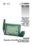
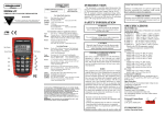
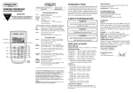
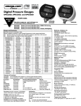
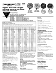
User’s Guide
Shop online at
omega.com
e-mail: [email protected]
For latest product manuals:
omegamanual.info
IP710 SERIES
I/P Converters
OMEGAnet ® Online Service
www.omega.com
Internet e-mail
[email protected]
Servicing North America:
USA:
ISO 9001 Certified
Canada:
One Omega Drive, P.O. Box 4047
Stamford CT 06907-0047
TEL: (203) 359-1660
e-mail: [email protected]
976 Bergar
Laval (Quebec) H7L 5A1, Canada
TEL: (514) 856-6928
e-mail: [email protected]
FAX: (203) 359-7700
FAX: (514) 856-6886
For immediate technical or application assistance:
USA and Canada: Sales Service: 1-800-826-6342 / 1-800-TC-OMEGA®
Customer Service: 1-800-622-2378 / 1-800-622-BEST®
Engineering Service: 1-800-872-9436 / 1-800-USA-WHEN®
TELEX: 996404 EASYLINK: 62968934 CABLE: OMEGA
Mexico:
En Espan˜ol: (001) 203-359-7803
FAX: (001) 203-359-7807
e-mail: [email protected]
[email protected]
Servicing Europe:
Benelux:
Postbus 8034, 1180 LA Amstelveen, The Netherlands
TEL: +31 (0)20 3472121
FAX: +31 (0)20 6434643
Toll Free in Benelux: 0800 0993344
e-mail: [email protected]
Czech Republic:
Frystatska 184, 733 01 Karviná, Czech Republic
TEL: +420 (0)59 6311899
FAX: +420 (0)59 6311114
Toll Free: 0800-1-66342
e-mail: [email protected]
France:
11, rue Jacques Cartier, 78280 Guyancourt, France
TEL: +33 (0)1 61 37 29 00
FAX: +33 (0)1 30 57 54 27
Toll Free in France: 0800 466 342
e-mail: [email protected]
Germany/Austria: Daimlerstrasse 26, D-75392 Deckenpfronn, Germany
TEL: +49 (0)7056 9398-0
Toll Free in Germany: 0800 639 7678
e-mail: [email protected]
FAX: +49 (0)7056 9398-29
United Kingdom: One Omega Drive, River Bend Technology Centre
ISO 9002 Certified
Northbank, Irlam, Manchester
M44 5BD United Kingdom
FAX: +44 (0)161 777 6622
TEL: +44 (0)161 777 6611
Toll Free in United Kingdom: 0800-488-488
e-mail: [email protected]
It is the policy of OMEGA to comply with all worldwide safety and EMC/EMI regulations that
apply. OMEGA is constantly pursuing certification of its products to the European New Approach
Directives. OMEGA will add the CE mark to every appropriate device upon certification.
The information contained in this document is believed to be correct, but OMEGA Engineering, Inc. accepts
no liability for any errors it contains, and reserves the right to alter specifications without notice.
WARNING: These products are not designed for use in, and should not be used for, patient-connected applications.
WARRANTY/DISCLAIMER
OMEGA ENGINEERING, INC. warrants this unit to be free of defects in materials and workmanship for a
period of 13 months from date of purchase. OMEGA’s WARRANTY adds an additional one (1) month
grace period to the normal one (1) year product warranty to cover handling and shipping time. This
ensures that OMEGA’s customers receive maximum coverage on each product.
If the unit malfunctions, it must be returned to the factory for evaluation. OMEGA’s Customer Service
Department will issue an Authorized Return (AR) number immediately upon phone or written request.
Upon examination by OMEGA, if the unit is found to be defective, it will be repaired or replaced at no
charge. OMEGA’s WARRANTY does not apply to defects resulting from any action of the purchaser, including but not limited to mishandling, improper interfacing, operation outside of design limits,
improper repair, or unauthorized modification. This WARRANTY is VOID if the unit shows evidence of
having been tampered with or shows evidence of having been damaged as a result of excessive corrosion;
or current, heat, moisture or vibration; improper specification; misapplication; misuse or other operating
conditions outside of OMEGA’s control. Components which wear are not warranted, including but not
limited to contact points, fuses, and triacs.
OMEGA is pleased to offer suggestions on the use of its various products. However,
OMEGA neither assumes responsibility for any omissions or errors nor assumes liability for any
damages that result from the use of its products in accordance with information provided by
OMEGA, either verbal or written. OMEGA warrants only that the parts manufactured by it will be
as specified and free of defects. OMEGA MAKES NO OTHER WARRANTIES OR
REPRESENTATIONS OF ANY KIND WHATSOEVER, EXPRESS OR IMPLIED, EXCEPT THAT OF TITLE,
AND ALL IMPLIED WARRANTIES INCLUDING ANY WARRANTY OF MERCHANTABILITY AND
FITNESS FOR A PARTICULAR PURPOSE ARE HEREBY DISCLAIMED. LIMITATION OF
LIABILITY: The remedies of purchaser set forth herein are exclusive, and the total liability of
OMEGA with respect to this order, whether based on contract, warranty, negligence,
indemnification, strict liability or otherwise, shall not exceed the purchase price of the
component upon which liability is based. In no event shall OMEGA be liable for
consequential, incidental or special damages.
CONDITIONS: Equipment sold by OMEGA is not intended to be used, nor shall it be used: (1) as a “Basic
Component” under 10 CFR 21 (NRC), used in or with any nuclear installation or activity; or (2) in medical
applications or used on humans. Should any Product(s) be used in or with any nuclear installation or
activity, medical application, used on humans, or misused in any way, OMEGA assumes no responsibility
as set forth in our basic WARRANTY/ DISCLAIMER language, and, additionally, purchaser will indemnify
OMEGA and hold OMEGA harmless from any liability or damage whatsoever arising out of the use of the
Product(s) in such a manner.
RETURN REQUESTS/INQUIRIES
Direct all warranty and repair requests/inquiries to the OMEGA Customer Service Department. BEFORE
RETURNING ANY PRODUCT(S) TO OMEGA, PURCHASER MUST OBTAIN AN AUTHORIZED RETURN
(AR) NUMBER FROM OMEGA’S CUSTOMER SERVICE DEPARTMENT (IN ORDER TO AVOID
PROCESSING DELAYS). The assigned AR number should then be marked on the outside of the return
package and on any correspondence.
The purchaser is responsible for shipping charges, freight, insurance and proper packaging to prevent
breakage in transit.
FOR WARRANTY RETURNS, please have the
following information available BEFORE
contacting OMEGA:
1. Purchase Order number under which the product was PURCHASED,
2. Model and serial number of the product under
warranty, and
3. Repair instructions and/or specific problems
relative to the product.
FOR NON-WARRANTY REPAIRS, consult OMEGA
for current repair charges. Have the following
information available BEFORE contacting OMEGA:
1. Purchase Order number to cover the COST
of the repair,
2. Model and serial number of the product, and
3. Repair instructions and/or specific problems
relative to the product.
OMEGA’s policy is to make running changes, not model changes, whenever an improvement is possible. This affords our
customers the latest in technology and engineering.
OMEGA is a registered trademark of OMEGA ENGINEERING, INC.
© Copyright 2002 OMEGA ENGINEERING, INC. All rights reserved. This document may not be copied, photocopied, reproduced, translated, or reduced to any electronic medium or machine-readable form, in whole or in part, without the prior
written consent of OMEGA ENGINEERING, INC.
IP710 SERIES
I/P Converters
2.94
74.7
1.00
25.4
.500
12.7
22 GA. wire leads
approx. 18" long
pos, neg, grd
Mounting Holes
#10–32 UNF–2B
X 3/8 Deep
2 Places
1
NPT
2
.125
Vent
3.17
3.69
93.7
1.30
33.0
1.50
38.1
3.12
79.2
1.13
28.7
1.80
45.7
.516
13.1
2.18
55.4
In and out ports
1/4–20 NPT
4 places
Back view typical of all units
.383
9.72
.766
19.4
Contents
Section
Description
Page
1.0
Description & Installation
3
2.0
Operation
6
3.0
Maintenance & Repairs
8
4.0
Troubleshooting
8
5.0
Warning
8
Page 1
DANGER, WARNING, CAUTION and NOTE statements
DANGER Refers to conditions or hazards which could result in serious personal injury or death.
WARNING Refers to conditions or hazards which could result in personal injury.
CAUTION Refers to conditions or hazards which could result in equipment or property damage.
NOTE
Alerts you to facts or special instructions.
ALL DANGER, WARNING, AND CAUTION NOTICES MUST BE COMPLIED WITH IN FULL
SPECIFICATIONS
Functional Specifications
Inputs
Outputs
psig
(BAR)
Supply
Pressure
psig
(BAR)
Air Consumption
*Zero-based units have
slightly higher air consumption
Flow Capacity
Temperature Limits
Loop Load,
I/P Transducer
Standard Range
4-20 mA
High Output Range
1-17
(0.07-1.2)
3-15
(0.2-1.0)
3-27
(0.2-1.8)
6-30
(0.4-2.0)
2- 60
(0.14-4.0)
2-100
(0.14-6.9)
22-60
(1.5-4.0)
20-100
(1.4-6.9)
32-100
(2.2-6.9)
35-100
(2.4-6.9)
65-100
(4.5-6.9)
105-130
(7.2-9.0)
1.5 scfh (0.04 m3/hr) at
mid range typical
4.5 scfh (0.13 m3/hr) at
mid range typical
4.5 scfm (7.6 m3/hr) at
25 psig (1.7 BAR) supply
20.0 scfm (34.0 m3/hr) at
130 psig (9.0 BAR) supply
12.0 scfm (20.0 m3/hr) at
100 psig (7.0 BAR) supply
Operating: -40º to +160º F (-40º to +71º C)
Storage: -40º to +200º F (-40º to +93º C)
9.5 VDC @ 20 mA
Performance Specifications
Accuracy, Hysteresis
and Repeatability
Deadband
Position Effect
Vibration Effect
Supply Pressure Effect
Temperature Effect
Reverse Polarity Effect
RFI/EMI Ef fect
±0.10% of span guaranteed
0.02% of span
No measurable effect
Less than ±1.0% of span under the following conditions:
5-15Hz @ 0.8 inches constant displacement 15-500Hz @ 10g s
No measurable effect
±0.045%/F (0.07%/C) of span
No damage occurs fr om reversal of normal supply current (4-20mA)
or from misapplication of up to 60mA
Pending
Physical Specifications
Port Sizes
Media
Mounting
Materials
Weight
Pneumatic: 1/4” NPT
Clean, dry, oil-free air-filtered to 40 micr on
Wall, panel, 2” pipe, or DIN rail (optional)
Housing: Chromate-tr eated aluminum with baked paint, NEMA 4X (IP65)
Elastomers: Buna-N
Trim: Stainless steel; brass; zinc-plated steel
13.0 oz. (0.4 kg)
Page 2
1. DESCRIPTION and INSTALLATION
1.1 Description
1.1.1
The Omega IP710 converts a current input signal to a linearly proportional pneumatic output pressure. This unit
utilizes a closed loop pressure feedback system that closely controls output and compensates for vibration,
mounting angle, temperature and supply pressure variations. The control mechanism is a piezoceramic actuator.
The unique properties of this actuator protect it against moisture and breakage associated with similar competitive technologies.
1.2 Principle of Operation
1.2.1
The IP710 transducer is a force balance device in which the piezo actuator is positioned in relation to a nozzle as the
input signal is varied. The application of an electrical signal causes axial movement of the actuator. The actuator
moves toward the nozzle and creates back pressure which acts as a pilot pressure to an integral booster relay.
1.3 Mounting
1.3.1
Each IP710 comes with a mounting kit which enables pipe, panel or wall mounting of the unit. An optional mounting kit is available for DIN-rail mountings. The IP710 may be mounted at any angle.
1.3.2
Panel: With access to rear of panel, attach transducer to panel using two 10-32 screws and the two threaded
mounting holes on the back of the unit. With no access to the rear of a panel, attach bracket to transducer using
two 10-32 holes on the back of the unit and mount bracket to panel using four 10-32 screws (see figure 1).
Figure 1 - Standard Panel Mount
1.50
38.1
.312
7.92
.281
7.14
4.86
123.4
4.50
114.3
2.43
61.7
Mount using
(2) #1/4–20 screws
not included in kit
1.3.3
In- Line: Due to it’s light weight, the IP710 may be supported by the piping used for supply and output.
1.3.4
11/2” Pipe: Attach bracket to transducer using two 10-32 holes on the back of unit. Place U-bolt around pipe and
through bracket. Place nuts on U-bolt and tighten (see figure 2).
Figure 2 - Standard 11/2” Pipe Mount
.312
7.92
Pipe clamp for
1–1/2 pipe
1.50
38.1
1.80
45.7
Standard bracket shown
with breakaway tabs removed
2.25
57.2
3.36
85.3
Page 3
Figure 3 - DIN 43650 Connector
DIN Rail mounting kit IP610-DM
.61
15.5
3.90
1.40
3.08
1.68
42.7
1.29
DIN Rail Kit suitable for EN-50035, EN-50045 and EN-50022 Rails
1.4 Pneumatic Connections
1.4.1
Clean all pipe lines to remove dirt and scale before installation.
1.4.2
Supply air must be filtered to 40 microns and free of moisture and lubricants.
1.4.3
The 1/4” NPT inlet and outlet connections are labeled on the body. Plug all unused ports with pipe plugs supplied
with the unit. Avoid getting pipe sealant inside the piping or transducer.
1.5 Electrical Connections
1.5.1
Conduit Connection (current to pressure) Electrical connections are made to the red (+) and black (-) leads. The
green lead is furnished for case ground (see figure 4).
Figure 4
I/P Conduit Connection
Green Lead (Ground)
Red Lead (+)
Black Lead (-)
Figure 5 - DIN 43650 Connector
2
1
Terminal
I/P Connection
1
Positive (+)
2
Negative (-)
3
Unused
3
Ground (+)
Figure 6 - I/P Conduit Connection
Page 4
1.6 Factory Mutual Research Corporation (FM)
and Canadian Standards association (CSA)
Intrinsically Safe
Suitable for:
Class I, II, III, Div. 1,
Groups C, D, E, F & G
Models IP710–*
Suitable for:
Class I, Div. 2, Groups A, B, C & D
Models IP710–*
IP710–*
Class II & III, Div. 2, Groups F & G
Models IP710–*
*= Ouput pressure option does not
affect rating
Class I, Div. 1, Groups C & D
Models IP710–*
Factory Mutual and Canadian Standards Association I.S. Installation Drawing
IP710
Transducer
+
3
(Red)
-
4
(Black)
28V
Single
Channel
Polarized
4–20mA
1
OV
Rail
2
Type 1
System
Controller
IP710
Transducer
+
3
(Red)
-
4
(Black)
28V
TwoChannel
Polarized
Diode
4–20mA
1
2
4–20mA
1-5V
Type 2
System
OV
Rail
Controller
IP710
Transducer
+
3
(Red)
-
4
(Black)
Hazardous
Location
28V
TwoChannel
Polarized
10V
Non-hazardous
Location
4–20mA
1
2
4–20mA
1-5V
Type 3
System
OV
Rail
Controller
Notes:
1. Control equipment connected to the Associated Apparatus must not use or generate more than 250 Vrms or Vdc.
2. The IS Barriers or Equipment (Associated Apparatus) must be FM Approved and CSA Certified and the
configuration of Associated Apparatus must be FM Approved and CSA Certified under the Entity Concept. The
Associated Apparatus may be installed within the Hazardous (Classified) location for which it is certified. The
Associated Apparatus and hazardous location loop apparatus manufacturer’s control drawings must be followed
when installing this equipment. An AEx [ib] Associated Apparatus is suitable only for connection to Class I, Zone
1, Hazardous (Classified) Locations and is not suitable for Class I, Zone 0, or Class I, Division 1 Hazardous
(Classified) Locations.
3. Installation should be in accordance with ANSI/ISA RP12.6 “Installation of Instrinsically Safe Systems for
Hazardous (Classified) Locations” and Article 500 of the National Electrical Code (ANSI/NFPA 70).
4. The standard conduit is suitable for Type 4X installations. All others must be mounted in a suitable enclosure.
5. The standard conduit is suitable for Class I, II and III, Division 2, Groups A, B, C, D, F & G hazardous (classified)
locations. Dust-tight conduit seal must be used when installed in Class II and Class III environments.
The connection option “D” is suitable for Class I, Division 2, Groups A, B, C and D hazardous (classified) locations.
Transducers to be installed in accordance with National Electrical Code (ANSI/NFPA 70) Division 2 hazardous
(classified) location wiring techniques.
6. The Instrinsic Safety Entity concept allows the interconnection of two FM Approved or CSA Certified intrinsically
safe devices with entity parameters not specifically examined in combination as a system when:
Ui or Vmax >Uo or Voc or Vt > 7.2 volts
li or Imax > lo or lsc or It
Ca or Co > Ci + Ccable
La or Lo > Li + Lcable
Pi > Po.
Entity Parameters for Models IP710–*
Ui (Vmax) = 30 V
Ii (Imax) = 125 mA
Pi = 0.7o watts
Ci = 0 uF
Li = 0 mH
7. No revision to this drawing is permitted without prior Factory Mutual Research Approval.
Page 5
2. OPERATION
2.1 Calibration
2.1.1
All units are shipped from the factory calibrated, direct acting.
2.1.2
If the user requires a different mode of operation (i.e. reverse acting, split range) it is necessary to reposition internal electrical switches as indicated below. Though the units are factory calibrated for direct acting it is suggested
that the user check the calibration.
2.1.3
It is not necessary to remove the cover of the unit for calibration if the direct acting mode is desired.
2.2 Direct Acting Calibration
2.2.1
In direct acting operation the unit is calibrated so that minimum input signal corresponds to minimum output
pressure and increasing input signal results in increasing output pressure.
2.2.2
Apply the minimum input signal of the range being used (e.g. 4mA for a 4-20mA unit) (see figure 6).
2.2.3
Observe the output pressure. If necessary, adjust the zero screw until reaching minimum output pressure setting.
Turn zero screw clockwise to decrease and counter clockwise to increase.
2.2.4
Apply the maximum input signal of the range being used (e.g. 20mA for a 4-20mA unit).
2.2.5
Observe the output pressure. If necessary, adjust the span screw until reaching maximum output pressure setting.
Turn span screw clockwise to decrease and counter clockwise to increase.
2.2.6
After setting the span it will be necessary to recheck the zero. Repeat steps 1-4 until both end points are at
required values.
Figure 6 - Zero Adjustment and Span Adjustment
Zero Adjustment
Span Adjustment
Figure 7 - Direct Acting - Position of switches for forward acting operation (all output ranges).
Standard setting as supplied by factory.
Signal
4-20 mA
Page 6
2.3 Reverse Acting Calibration
2.3.1
When calibrated to operate in the reverse acting mode the minimum input signal produces the maximum output
pressure and increasing the input signal results in decreasing the output pressure. Setting the unit to operate in
the reverse acting mode is accomplished by positioning internal electrical switches.
CAUTION
2.3.2
Do not reverse the input leads.
Disconnect input signal and supply pressure. Take off the top cover by removing the four screws.
CAUTION
Avoid touching circuit board. Shorting possible.
2.3.3
Position switches as illustrated in figure 8. Replace cover.
2.3.4
Set the input signal to the minimum valve being used. Turn the zero screw to set the maximum output pressure.
2.3.5
Set the span by applying the maximum input signal. Turn the span screw to set the minimum output pressure.
2.3.6
It may be necessary to repeat steps 2.3.4 – 2.3.5 until both end points are at desired values.
Figure 8 - Position of switches for Reverse Acting Operation
Note: Switches not shown match Direct Acting Settings (see figure 7).
2.4 Split Range
2.4.1
When calibrated to operate in the split range mode, a full input signal (i.e. 4-20mA) will operate the unit
at one half the normal output span (i.e. 3-9 psig, 9-15 psig). Setting the unit to operate in the split range
mode is accomplished by positioning internal electrical switches.
2.4.2
Disconnect input signal and supply pressure. Take off the top cover of the unit by removing the four screws.
CAUTION
Avoid touching circuit board. Shorting possible.
2.4.3
Position switches as illustrated in figure 9. Replace cover
2.4.4
After setting switches, refer to the appropriate calibration procedure (Direct Acting or Reverse Acting) to get to
desired output range (i.e. 3-9 psig, 9-15 psig).
Figure 9 - Position of switches for Split Range Operation
4-20 mA
Note: Switches not shown match Direct Acting Settings (see figure 7).
Page 7
3. MAINTENANCE AND REPAIRS
NOTE
Under normal circumstances, no maintenance should be required.
3.1 Cleaning
3.1.1
If clean, dry air is not used the orifice can become blocked. To clear, first turn off supply air, then remove the
screw located under the zero adjustment. The orifice is located between the two black o-rings. You may need a
magnifying glass to see it. Unplug the orifice by running a wire that has a smaller diameter than 0.012” (0.30mm)
through it.
3.1.2
Used compressed air to blow out any loose particles inside the orifice screw assembly.
3.2 Precautions
3.2.1
The bonnet should be removed only if a different operation mode is desired which requires a change in circuit
board switch settings. In this case, precautions are necessary.
3.2.2
Never handle circuit board unless properly grounded to prevent ESD (Electro-static Discharge).
3.2.3
If ESD grounding equipment is not available, hold the IP710 by its castings and adjust switches using a non-conductive devise such as a pencil or a small rubber handled screwdriver.
3.2.4
Never remove circuit board for any reason. This will shift other components and possibly damage the pressure
sensor, both cases resulting in malfunction.
3.2.5
Use caution when replacing bonnet. If any resistance is felt, remove bonnet and determine the interference.
Typically it will be the strain relief grommet on the wires. The grommet should be oriented so it sits beside the
switches.
3.2.6
Clean, dry air should be used with the IP710. Foreign matter in the supply line can clog the orifice openings.
(.013” for a 3-15 psig unit, smaller for higher range units.) Foreign matter can also collect on the actuator causing
erratic operation. Moisture in the supply line can damage circuit board components.
3.2.7
The electrical specifications as outlined in the IP710 instructions must be complied with. If more than one IP710
mA unit is driven by the same PLC, there must be a minimum of 9.5 v DC available to each unit. For a IP710 voltage unit, there must be a constant supply voltage of 7-30 v DC applied to the red wire. The variable control voltage is applied to the orange wire.
3.2.8
If difficulty is experienced during calibration or if turning the zero or span screw has no effect on the unit, a resetting technique can be taken. Turn both the zero and span screw a minimum of 30 revolutions in one direction.
Then turn both screws exactly 15 revolutions in the opposite direction. This procedure will put the potentiometers
at their midpoint of effective adjustability. Next, calibrate to desired settings starting with the zero screw.
3.2.9
Reverse Acting Mode: For reverse acting units, the zero adjustment refers to the minimum electrical signal and
maximum output pressure. The span refers to the maximum signal and the minimum output pressure. For calibration in reverse mode the resetting technique can be taken if necessary and calibration should always begin with
the zero screw.
4. TROUBLESHOOTING
PROBLEM
CHECK
SOLUTION
Sluggish performance
or reduced range
Blocked orifice
Supply pressure
Clean orifice (3.1)
Increase supply pressure (see specs)
Leakage
Connections
Check seal at port
Low or improper span
Supply pressure
Connections
Increase supply pressure (see specs)
Check seal at port
Erratic operation
Moisture in air supply
Loose wires or connections
Dip switch settings
Use clean, dry air (see specs)
Check wiring (1.5)
Reset dip switches (2.2/2.3/2.4)
5. WARNING
FAILURE MODES: This device must not be used for protecting final control elements connected to the output port from the effect of
pressure present at the supply port. If devices connected to the output port have a pressure rating less than the pressure present at
the supply port, then pressure relieving or pressure limiting devices must be employed to protect the devices from over pressurization, possibly causing physical damage, personal injury and/or property damage.
Page 8
Where Do I Find Everything I Need for
Process Measurement and Control?
OMEGA…Of Course!
Shop online at www.omega.com
TEMPERATURE
M
U
M
U
M
U
M
U
M
U
Thermocouple, RTD & Thermistor Probes, Connectors, Panels & Assemblies
Wire: Thermocouple, RTD & Thermistor
Calibrators & Ice Point References
Recorders, Controllers & Process Monitors
Infrared Pyrometers
PRESSURE, STRAIN AND FORCE
M
U
M
U
M
U
M
U
Transducers & Strain Gages
Load Cells & Pressure Gages
Displacement Transducers
Instrumentation & Accessories
FLOW/LEVEL
M
U
M
U
M
U
M
U
Rotameters, Gas Mass Flowmeters & Flow Computers
Air Velocity Indicators
Turbine/Paddlewheel Systems
Totalizers & Batch Controllers
pH/CONDUCTIVITY
M
U
M
U
M
U
M
U
pH Electrodes, Testers & Accessories
Benchtop/Laboratory Meters
Controllers, Calibrators, Simulators & Pumps
Industrial pH & Conductivity Equipment
DATA ACQUISITION
M
U
U
M
M
U
M
U
M
U
Data Acquisition & Engineering Software
Communications-Based Acquisition Systems
Plug-in Cards for Apple, IBM & Compatibles
Datalogging Systems
Recorders, Printers & Plotters
HEATERS
U
M
M
U
M
U
M
U
M
U
Heating Cable
Cartridge & Strip Heaters
Immersion & Band Heaters
Flexible Heaters
Laboratory Heaters
ENVIRONMENTAL
MONITORING AND CONTROL
M
U
M
U
U
M
M
U
M
U
M
U
P/N 541-622-081
Metering & Control Instrumentation
Refractometers
Pumps & Tubing
Air, Soil & Water Monitors
Industrial Water & Wastewater Treatment
pH, Conductivity & Dissolved Oxygen Instruments
M-4063/0307