1
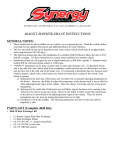
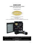
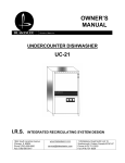
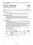
PRODUCT INSTRUCTION SHEET
FCLTX-100 Series
SECTION 1.0
THEORY OF OPERATION
1.0 FREE CHLORINE DEFINED. Free Chlorine or "freely active chlorine"
is defined as the sum of molecular chlorine (Cl2), hypochlorous acid
(HOCl) and hypochlorite ions (OCl-). Molecular chlorine occurs at
pH values <pH4. Hypochlorus acid and hypochlorite ions are in pH
dependent equilibrium with one another as shown in FIG 1.
The graph shows % hypochlorous acid on the left of the curve.
Hypochlorous acid is a much stronger disinfecting agent (oxidizer) as
compared to hypochlorite ions.
1.2 SENSOR OPERATING PRINCIPLE. Both hypochlorous acid (HOCl)
and hypochlorite ion (OCl-) diffuse through the membrane between
the cathode and sample solution, even though the diffusion coefficients for each are different. At the applied potential, only hyphochlorous acid is electrochemically reduced. HOCl is reduced to chloride
ion at the gold cathode. At the same time, the silver anode is oxidized
to form silver chloride (AgCl). When the concentration of HOCl at
the cathode is dramatically decreased by electrochemical reduction,
hypochlorite ion will be transformed into hypochlorous acid , to some
extent, by proton transfer. The release of electrons at the cathode
and acceptance at the anode creates a current flow, which under
constant conditions, is proportional to the free chlorine concentration
in the medium outside the sensor. The resulting low current output
is then conditioned to 4-20mA current by the sensor's onboard electronic circuitry.
SECTION 2.0
FACTORS INFLUENCING THE SENSOR
(sensor output in mA – 4)/(-0.0502pH3 + 0.867pH2 – 5.051pH + 12.43) + 4
Percent of free chlorine in protonated form (HClO)
90
80
70
OCl-
60
percent
2.1 pH. Free Chlorine (FCL) exists as hypochlorous acid and hypochlorite anion (FIG 1). The acid-base dissociation of FCL has a pKa
of approximately 7.5. The FCL sensor responds to hypochlorous
acid and hypochlorite anion with different sensitivity. In combination, an increase in pH reduces the measured FCL and decrease in pH
increases the measured FCL. The need for automatic pH compensation depends on the pH value and the variation range of pH (Table
1). If pH variation of your sample is more than that listed in the table,
automatic pH compensation is required. pH compensation for the
sensors current (mA) reading is:
FIG. 1
100
HOCl
50
40
30
20
10
2.2 Chemical Interferences. The sensors should not be used in water
containing surfactants, organic chlorine or stabilizers such as cyanuric
acid.
2.2 FLOW. The membrance covered free chlorine sensors (FCL series)
functions at any flow rate. To acheive reproducible measurements,
these free chlorine sensors require a specified constant flow rate. To
avoid complications (such as bubbles), it is best to operate the sensors at a flow rate of 0.2-0.6 gpm if using flow cell FC72 or FC70 (old
version).
0
5
5.5
6
6.5
7
7.5
8
8.5
9
9.5
pH
TABLE 1
pH Range
<6.5
6.5-7.5
7.5-8.3
8.3-9.0
pH Variation
N/A
+ 0.35
+ 0.20
+ 0.05
M4679/0708 page 1 of 6
Parts covered by this product instruction sheet include: FCLTX-100 Series
10
PRODUCT INSTRUCTION SHEET
SECTION 3.0
SENSOR PREPARATION
FIG. 2
3.0 FREE CHLORINE SENSOR ASSEMBLY. The Free Chlorine
Sensor is shipped with the membrane cap pre-installed and
covered with a cap with water inside to keep the membrane
wet. Make sure to keep sensor cap, anode and cathode inside
the sensor body, away oily or greasy materials. Contact with oil
or grease will result in inaccurate measurements.
SENSOR
SNAP RING
GROOVE
NOTE: IF SENSOR WILL BE STORED DRY OUT OF FLOW
CELL, SHAKE BODY DOWNWARD INTO A SINK TO REMOVE THE
FILL SOLUTION. TAKE THE MEMBRANE CAP AND IMMERSE IN A
CUP OF TAP WATER UNTILL READY TO REUSE. SEE
SECTION 9. REPLACE CAP AND ELECTROLYTE BEFORE INSTALLING INTO FLOW CELL (see SECTION 10 for cap and electrolyte
change. See SECTION 5 for sensor installation into flow cell).
THREADED FITTING
SNAP RING (INSTALLS
INTO PROBE GROOVE)
SECTION 4.0
FLOW CELL INSTALLATION
O-RING
4.0 FLOW CELL. To obtain accurate Free Chlorine reading,
the Sensor must be installed into the Flow Cell to prevent air
bubbles formation on the membrane, proper spacing between
the sensor and the installation wall, and laminar flow across
the membrane.
4.1. Using two 1/4” NPT Tube fittings, connect the FC72 Flow
Cell into your system, noting the inlet (bottom) and outlet
(side) orientation. (see FIGURE 2)
4.2. Install clamp with rubber backing as shown in FIG. 2A.
4.3 Drill 3/8" diameter hole on the panel.
4.4 Insert bolt as shown in FIG 2A
4.5 On back of panel attach lock washer and nut to secure
clamp and flow cell to panel.
BARBED TUBE
FITTING
FLOW CELL
FC72 Flow cell
BARBED TUBE
FITTING
FIG. 2A
SECTION 5.0
SENSOR INSTALLATION
5.0 SENSOR INSTALLATION INTO FLOW CELL.
a. First install threaded fitting onto sensor body
(remove fitting if pre-installed in flow cell)
b. Install snap-ring into groove on sensor body
c. Next, slide o-ring onto body of sensor until it
reaches bottom of threaded fitting.
d. Thread sensor assembly into top of flow cell as
shown in FIGURE 2.
d. Turn on flow and verify the flow through the Flow
Cell is at least 0.2gpm (45 liters/hour and no
more than 0.6gpm (135 liters/hour).
M4679/0708 page 2 of 6
Parts covered by this product instruction sheet include: FCLTX-100 Series
PRODUCT INSTRUCTION SHEET
SECTION 6.0
ELECTRICAL INSTALLATION
FIG. 3
Power Supply
sensor red wire
6.0 ELECTRICAL INSTALLATION. The sensor produces an approximate output of 4 mA in air and 20mA at the top range of
free chlorine output (0-2ppm, 0-5ppm, 0-10ppm).
NOTE: The supply voltage to the Sensor must be 12-24 V DC with
minimum of 250 mA. Maximum load is 1 Watt. The sensor has 3 wires,
red (+) , black (-) and clear (shield). Twist together or solder black
and clear if instrument does not have separate ground. If a separate
ground is available such as for PLC’s connect clear (shield) to it.
Attach the red wire to the power supply positive terminal (+)and the
black wire to the PLC or DVM positive (+) terminal. Connect a wire
(customer supplied) from the power suppy negative (-) and the PLC or
DVM (-). See FIG 3. The Sensor will require several minutes to stabilize
after power is supplied to it.
sensor
black wire
PLC, DVM,...
SECTION 7.0
SENSOR CONDITIONING
7.0 SENSOR CONDITIONING The sensor requires conditioning
prior to generating stable values.
a. For new Sensors, allow the Sensor to run for at least
4 hours before calibration.
b. If the Sensor will be un-powered for 2 hours or
more, run for 3 hours prior to use.
c. After membrane/electrolyte replacement, allow the
Sensor to run for at least 4 hours.
M4679/0708 page 3 of 6
Parts covered by this product instruction sheet include: FCLTX-100 Series
PRODUCT INSTRUCTION SHEET
SECTION 8.0
CALIBRATION
FIG. 4
FIG. 5
FIG. 6
FIG. 7
IMPORTANT NOTE: SENSORS ARE SUPPLIED FACTORY CALIBRATED WITH A
4-20mA SIGNAL OUTPUT CORRESPONDING TO THEIR SPECIFIC RANGE (0-2,
0-5 OR 0-10ppm). SPAN CALIBRATION IS NECESSARY WHEN RECEIVING A
NEW SENSOR SINCE YOUR CONDITIONS MAY VARY FROM THOSE USED AT
THE FACTORY FOR SPAN CALIBRATION. THE ZERO POINT CALIBRATION IS
NOT NECESSARY SINCE THE ZERO SETTING IS VERY STABLE.
PERIODIC CALIBRATION ( ABOUT ONCE PER WEEK) IS RECOMMENDED. THIS
IS USEFUL IN TRACKING SENSOR FAILURES AS WELL.
8.1 Removal of cord grip to access ZERO and SPAN
potentiometers inside the sensor body:
a. Remove top nut of cord grip as shown in FIGURE 4.
b. Remove remaining cord grip as shown in FIGURE 5. A wrench
may be required.
8.2 Slope Calibration:
a. Determine the free chlorine content using a diethyl-pphenylenediamine (DPD) colorimeter test kit (see FIGURE 9.),
not included with ClO2 sensor and flow cell.
b. Measure Free Chlorine content with sensor. Make sure that
calibration flow rate and pH matches flow rate when
measuring sample since probe output is flow rate and pH
dependent. Make sure pH is within 5.5-8.0 range.
c. Adjust the span potentiometer to the desired mA (see
FIGURES 9 & 9A)
c. Repeat this slope calibration one day after sensor is
initially installed.
d. Repeat the slope calibration monthly.
Left
potentiometer
(Zero adjust)
Right
potentiometer
(Span adjust)
Cable
FIG. 8
SECTION 9.0
SENSOR STORAGE
9.0 STORAGE. Store sensor at 5o C- 50o C ONLY and maximum
humidity of 90% (non-condensing).
a. Short Term Storage (1 week or less): Store in Flow cell
with water to prevent the probe from drying out.
b. Intermediate Term (1 week to 1 month): Store in cap,
bottle, or beaker with water to keep membrane wet.
c. Long Term (1 month or longer): Remove Membrane
Cap and store completely immersed in tap water. Turn
sensor upright and shake it to remove fill solution from
inside the sensor.
d. Electrolyte bottle shelf-life = 1 year from date of
manufature(see expiration date on bottle)
to Increase
output
to Decrease
output
FIG. 9
Free
C L OCl2
ZERO
Free
ClO2Cl
READ
Note: The DPD method
for Free chlorine measurement is not selective
for free chlorine alone.
Other oxidants in the
water can also be measured as free chlorine.
M4679/0708 page 4 of 6
Parts covered by this product instruction sheet include: FCLTX-100 Series
PRODUCT INSTRUCTION SHEET
SECTION 10.0
SENSOR MAINTENANCE/RECONDITIONING
FIG. 10
FIG. 11
10.1 GENERAL MAINTENANCE. Service the sensor regularly
(weekly is suggested)
INJECT UNTIL SOLUTION
LEAKS OUT OF FILL HOLE
10.2 MEMBRANE CAP REPLACEMENT. If membrane replacement is required, a new cap with preinstalled membrane must
be used. Order FCLA-2016 replacement membrane cap and
FCLA-2015 refill solution. To change membrane cap (do the
following over a sink or washbasin):
a) turn sensor upside down with cap facing upward
b) rotate cap counter-clockwise to remove (see FIG 10).
c) fill sensor body with electrolyte using needle and bottle of
refill solution (see FIG. 11)
d) install a new membrane cap by threading cap onto sensor
rotating cap clockwise (opposite of FIG 10)
10.3 MEMBRANE CAP/SENSOR CLEANING. Rinse cap with
water only. If cap does not clean, replace with new one.
SECTION 11.0
SENSOR TROUBLESHOOTING
11.1 CALIBRATION PROBLEMS
a) Sensor output HIGHER than DPD test
1) Run in time too short
2) Membrane cap damaged
3) Interference from water
contaminants (see Specifications,
"Cross Sensitivity")
4) Cable short circuit or damage
5) pH value less than pH 5.5
b) Sensor output LOWER than DPD test
1) Run in time too short
2) Deposits on Membrane cap
3) Flow rate too low
4) Air bubbles on membrane
5) Surfactants in water
6) pH value more than pH 8.0
7) No electrolyte in membrane cap
c) Sensor ouput is 4mA (zero ppm)
1) Run in time too short
2) Only bound chlorine present
3) Chlorine content below detection
limit
4) Sensor not wired correctly (See
SECTION 6.0 of this manual)
5) Defective sensor
d) Sensor output UNSTABLE
1) Air bubbles on membrane
2) Membrane damage
3) Non-sensor problem
TROUBLESHOOTING CHART
Symptom
Possible Cause
Solution/Remedy
The sensor
cannot be
calibratedouput is
HIGHER than
DPD Test
1) Run in time too short
2) Membrane cap damaged
3) Interference from contaminants
4) DPD chemicals bad
5) pH value < pH 5.5
1) See Sec 5.0 -CONDITIONING
2) Replace cap - See Sec 8.0
3) See SPECIFICATIONS
4) Use new DPD kit
5) Increase pH (5.5-8.0)
See SPECIFICATIONS
6) Match calibration temp.
6)Temperatue increased since cal
The sensor
cannot be
calibratedoutput is
LOWER than
DPD Test
1) Run in time too short
2) Deposits on membrane cap
1) See Sec 7.0 -CONDITIONING
2) Remove deposits or replace
cap if cleaning ineffective.
3) Flow rate too low
3) increase flow - See
SPECIFICATIONS
4) Air bubbles on membrane
4) Remove and re-install sen
sor to remove bubbles.
5) Surfactants in water
5) Remove surfactants and
replace cap
6) pH > pH 8.0
6) Lower pH (5.5-8.0)
See SPECIFICATIONS
7) No electrolyte in cap
7) Add new electrolyte, run in
sensor and re-calibrate
8) Temperature decreased since cal 8) Increase temp to match cal
9) Organic chlorination agents
9) Use chlorinating agents
present in water
per DIN 19643
Sensor output
is 4mA (0 ppm)
1) Only bound chlorine present
NO FREE CHLORINE
2) Run in time too short
3) Chlorine content below limit
4) No electrolyte in cap
5) Sensor electrical connection
wrong
Unstable output
from sensor
1) Check for Chloramine with
appropriate DPD test.
Replace water/ Rechlorinate.
2) See Sec 7.0 -CONDITIONING
3) Add chlorine and repeat
calibration
4) Refill electrolyte
5) See SECTION 6.0
1) Air bubbles on sensor membrane 1) Tap to remove bubbles
2) Membrane damaged
2) Replace membrane, run in
sensor and recalibrate.
3) Non-sensor problem
3) check PLC or I/O device
M4679/0708 page 5 of 6
Parts covered by this product instruction sheet include: FCLTX-100 Series
PRODUCT INSTRUCTION SHEET
SECTION 12.0
SENSOR SPECIFICATION
FC72 FLOW CELL DIMENSIONS
12.1 OPERATING SPECIFICATIONS. Follow all operating specifications,
especially for pH and flow rate as noted in the specification tables
below.
TECHNICAL SPECIFICATIONS
SENSOR
Dimensions:
Body Material:
Membrane Material:
O-ring material:
Cathode:
Anode:
Cable:
8.2"L x 1" dia
Black PVC
polyethersulfone
VitonR
Gold
Silver chloride (AgCl)
2 -conductor shielded, 10ft (3mtr)
tinned wire leads
FLOW CELL
Dimensions:
Material:
Connections:
5.58"H x 2.25"DIA
Acrylic
1/4" NPT inlet and outlet
OPERATING SPECIFICATIONS
Operating temperature range:
Maximum operating pressure:
Flow rate minimum:
Flow rate maximum:
pH range:
Output signal:
Power Requirement:
Cross-Sensitivity:
Chemical Compatibility:
0-45 degC
1 bar/14.7 psi/1atm
.20 gpm
0.6 ppm
5.5-9.0
4.0+/- 0.2mA in air (zero)
20mA +/- 0.2mA at high range
(2, 5 or 10ppm)
12-24 VDC, 250 mA minimum
ClO2, ozone, bromine
up to 50% ethanol/water or
up to 50% glycerol/water
SENSOR AND FLOW CELL INSTALLATION DIMENSIONS
MAINTENANCE/REPLACEMENT PARTS
FC72
Flow Cell, 1/4 inch FNPT inlet and outlet, includes:
2 each 1/4" barbed tube fittings, clamp, threaded
flow cell installation fitting
FCL-ES
Free Chlorine sensor fill solution, 30mL, 1 each
FCL-RM
FCL Replacement premembraned cap, 1 each
M4679/0708 page 6 of 6
Parts covered by this product instruction sheet include: FCLTX-100 Series